KTM 1290 Super Adventure Owner's Manual
Hide thumbs
Also See for 1290 Super Adventure:
- Owner's manual (344 pages) ,
- Manual (29 pages) ,
- Owner's manual (184 pages)
Table of Contents
Advertisement
Quick Links
Download this manual
See also:
Owner's Manual
Advertisement
Table of Contents

Related Manuals for KTM 1290 Super Adventure


Summary of Contents for KTM 1290 Super Adventure
- Page 1 OWNER'S MANUAL 2015 1290 Super Adventure US Art. no. 3213284en...
- Page 3 KTM accepts no liability for delivery options, devi- ations from illustrations and descriptions, misprints, and other errors.
- Page 4 DEAR KTM CUSTOMER ISO 9001(12 100 6061) According to the international quality management standard ISO 9001, KTM uses quality assurance processes that lead to the maximum possible quality of the products. Issued by: TÜV Management Service KTM Sportmotorcycle GmbH 5230 Mattighofen, Austria...
-
Page 5: Table Of Contents
TABLE OF CONTENTS View of vehicle, rear right side (vehicle differs TABLE OF CONTENTS MEANS OF REPRESENTATION ........8 slightly from photo) ..........26 Symbols used ............8 SERIAL NUMBERS ............28 Formats used............9 Chassis number ..........28 SAFETY ADVICE............10 Type label ............ - Page 6 TABLE OF CONTENTS Locking the steering ........... 42 7.9.3 "Trip 2" ............60 Unlocking the steering........43 7.9.4 "General Info" ..........61 6.10 Socket for electrical accessories ......44 7.9.5 "TPMS" ............61 6.11 Opening the filler cap......... 44 7.9.6 "Set Favorites"...
- Page 7 TABLE OF CONTENTS Adjusting the windshield adapter position .... 80 12 SUSPENSION SETTING..........111 Adjusting basic position of clutch lever ....82 12.1 Fork/shock absorber ......... 111 Adjusting the basic position of the hand brake 12.2 "Load"............. 111 lever ..............82 12.3 "Damping"...
- Page 8 TABLE OF CONTENTS 13.23 Installing the tank cover ........142 16.3 Removing the battery ........173 13.24 Removing the wind shield ......... 144 16.4 Installing the battery ........175 13.25 Installing the wind shield........144 16.5 Recharging the battery ........176 13.26 Removing the engine guard.......
- Page 9 TABLE OF CONTENTS 20 CLEANING, CARE ............217 29.3 Green and blue symbols........247 20.1 Cleaning motorcycle ......... 217 INDEX ................248 20.2 Checks and maintenance steps for winter operation............219 21 STORAGE ..............221 21.1 Storage ............221 21.2 Preparing for use after storage......
-
Page 10: Means Of Representation
All work marked with this symbol requires specialist knowledge and technical understanding. In the interest of your own safety, have these jobs performed by an authorized KTM workshop. There, your motorcycle will be optimally cared for by specially trained experts using the specialist tools required. -
Page 11: Formats Used
MEANS OF REPRESENTATION Formats used The typographical formats used in this document are explained below. Specific name Identifies a proprietary name. Name ® Identifies a protected name. Brand™ Identifies a brand available on the open market. Underlined terms Refer to technical details of the vehicle or indicate technical terms that are explained in the glossary. -
Page 12: Safety Advice
SAFETY ADVICE Use definition - intended use KTM sport motorcycles are designed and constructed to meet the normal demands of regular road and light offroad operation (dirt roads), but not for use on race courses. Info The motorcycle is only authorized for operation on public roads in the homologated version. -
Page 13: Degrees Of Risk And Symbols
SAFETY ADVICE Degrees of risk and symbols Danger Indicates a danger that will immediately and invariably lead to fatal or serious permanent injury if the appropriate measures are not taken. Warning Indicates a danger that is likely to lead to fatal or serious injury if the appropriate measures are not taken. Caution Indicates a danger that may lead to minor injuries if the appropriate measures are not taken. -
Page 14: Overview Of Labels
SAFETY ADVICE Overview of labels S00735-10... - Page 15 SAFETY ADVICE Canada type label Information on starting up USA type label Technical Information Information on noise emission Information on chain tension Information on emission control S00726-01 Canada type label...
- Page 16 SAFETY ADVICE Information on starting up S00725-01 S00730-01 USA type label...
- Page 17 SAFETY ADVICE Technical Information S00731-01 S00729-01 Information on noise emission...
-
Page 18: Reporting Safety Defects
If you believe that your vehicle has a defect which could cause an accident resulting in injury or death, you should immediately inform the National Highway Traffic Safety Administration (NHTSA) in addition to notifying KTM North America, Inc. If NHTSA receives multiple similar complaints, it may open an investigation, and if it finds that a safety defect exists in a group of vehicles, it may order a recall and remedy campaign. -
Page 19: Noise Emission Warranty
Noise emission warranty KTM Sportmotorcycle AG warrants that this exhaust system, at the time of sale, meets all applicable U.S. EPA Federal noise standards. This warranty extends to the first person who buys this exhaust system for purposes other than resale, and to all subsequent buyers. -
Page 20: Tampering Warning
SAFETY ADVICE Tampering warning Tampering with the noise control system is prohibited. Federal law prohibits the following acts or the causing thereof: 1 The removal or rendering inoperative by any person other than for purposes of maintenance, repair, or replacement, of any device or element of design incorporated into any new vehicle for the purpose of noise control prior to its sale or delivery to the ultimate pur- chaser or while it is in use, or 2 the use of the vehicle after such device or element of design has been removed or rendered inoperative by any person. -
Page 21: Protective Clothing
Wear protective clothing (helmet, boots, gloves, pants and jacket with protectors) every time you ride the vehicle. Always wear protective clothing that is in good condition and meets the legal requirements. In the interest of your own safety, KTM recommends that you only operate the vehicle while wearing protective clothing. 2.12 Work rules Special tools are necessary for some of the work. -
Page 22: Environment
Keep the Owner's Manual in an accessible place to enable you to refer to it as needed. If you would like to know more about the vehicle or have questions on the material you read, please contact an authorized KTM dealer. -
Page 23: Important Notes
Warranty The work specified in the service schedule may only be performed in an authorized KTM workshop and must be recorded in both the Service & Warranty Booklet and in KTM Dealer.net, otherwise any warranty coverage will become void. No warranty claims can be considered for damage resulting from manipulations and/or alterations to the vehicle. -
Page 24: Service
Please follow the instructions in the text. Customer service Your authorized KTM dealer will be happy to answer any questions you may have on your vehicle and KTM. A list of authorized KTM dealers can be found on the KTM website. -
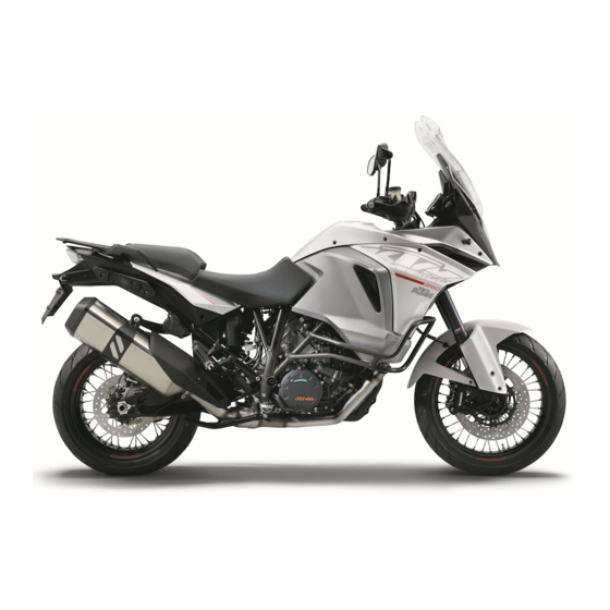
Page 26: View Of Vehicle
VIEW OF VEHICLE View of vehicle, front left side (vehicle differs slightly from photo) S00732-10... - Page 27 VIEW OF VEHICLE Socket for electrical accessories ( p. 44) Clutch lever ( p. 32) Grab handles ( p. 49) Luggage rack plate ( p. 49) Seat lock ( p. 48) Passenger footrest ( p. 50) Center stand ( p. 53) Rider footrests ( p.
-
Page 28: View Of Vehicle, Rear Right Side (Vehicle Differs Slightly From Photo)
VIEW OF VEHICLE View of vehicle, rear right side (vehicle differs slightly from photo) S00733-10... - Page 29 VIEW OF VEHICLE Combination switch, left side ( p. 33) Filler cap Combination switch, right ( p. 36) Throttle grip ( p. 33) Hand brake lever ( p. 32) Windshield locking lever Storage compartment Cooling system compensating tank Foot brake lever ( p.
-
Page 30: Serial Numbers
SERIAL NUMBERS Chassis number The chassis number is stamped on the bottom right of the frame behind the steering head. The chassis number is also shown on the type label. 402294-10 Type label Type label USA is affixed to the frame behind the steering head at the top right. 0 0 1 402174-10... -
Page 31: Key Number
SERIAL NUMBERS Type label Canada is affixed to the frame behind the steering head at the top left. 402293-11 Key number The key number Code number can be found on the KEYCODECARD. Info You need the key number to order a spare key. Keep the KEYCODECARD in a safe place. -
Page 32: Engine Number
SERIAL NUMBERS Engine number The engine number is stamped on the right side of the engine. 402296-10 Fork part number The fork part number is stamped on the inner side of the fork stub. 402295-10... -
Page 33: Shock Absorber Article Number
SERIAL NUMBERS Shock absorber article number The shock absorber article number is marked on a sticker on the shock absorber case under the spring. 402297-10... -
Page 34: Controls
CONTROLS Clutch lever The clutch lever is fitted on the left side of the handlebar. The clutch is hydraulically operated and self-adjusting. M00809-10 Hand brake lever The hand brake lever is fitted on the right side of the handlebar. The hand brake lever is used to activate both the front brake and rear brake at the same time. -
Page 35: Throttle Grip
CONTROLS Throttle grip The throttle grip is fitted on the right side of the handlebar. M00811-10 Switches on the left side of the handlebar 6.4.1 Combination switch, left side The left combination switch is fitted on the left side of the handlebar. Overview of the left combination switch Light switch ( p. -
Page 36: Light Switch
CONTROLS 6.4.2 Light switch The light switch is fitted on the combination switch on the left. Possible states Low beam on – Light switch in position . In this position, the low beam and tail light are switched on. High beam on –... -
Page 37: Menu Switch
CONTROLS 6.4.4 Menu switch The menu switch is fitted in the middle of the left combination switch. The menu buttons are used to control the matrix display on the combination instrument. Button is the UP button. Button is the DOWN button. ... -
Page 38: Horn Button
CONTROLS Info An automatic turn signal switch-off function (ATIR) is fitted as a standard software feature. The ATIR function uses a time and distance counter. If the turn signal has been on for at least 10 seconds and 150 meters of riding distance, the turn signal is switched off. -
Page 39: Emergency Off Switch
CONTROLS Overview of the right combination switch Emergency OFF switch ( p. 37) Switch for the cruise control system ( p. 38) Upper button of the cruise control system ( p. 39) Lower button of the cruise control system ( p. -
Page 40: Switch For The Cruise Control System
CONTROLS 6.5.3 Switch for the cruise control system The switch for the cruise control system is fitted on the right side of the combination switch. Possible states in the home position. – In this position, the cruise con- • Cruise control system switch trol system function is switched off. -
Page 41: Upper Button Of The Cruise Control System
CONTROLS – A fault occurring, which impairs the cruise control system function Warning Danger of accidents The cruise control system function is not suitable for all driving situations. The selected target speed will not be reached,if the engine power is not sufficient for a gradient. -
Page 42: Lower Button Of The Cruise Control System
CONTROLS Info The target speed is shown on the segment display of the combination instrument. After activation of the cruise control system function the throttle grip can be turned back to the home position. 6.5.5 Lower button of the cruise control system ... -
Page 43: Electric Starter Button
CONTROLS 6.5.6 Electric starter button The electric starter button is fitted on the right side of the handlebar. Possible states • Electric starter button in basic position. is pressed – In this position, the electric starter is actuated. • Electric starter button M00811-11 Ignition/steering lock... -
Page 44: Immobilizer
The black ignition keys are activated when delivered. Another two spare ignition keys (key number on the KEYCODECARD) can be ordered from an authorized KTM workshop; they need to be activated for use. Locking the steering Note Danger of damage The parked vehicle may roll away or fall over. -
Page 45: Unlocking The Steering
CONTROLS – Park the vehicle. – Turn the handlebar all the way to the left. – Insert the key into the ignition/handlebar lock, press in, and turn to the left. Remove the key. Steering is no longer possible. 400732-01 Unlocking the steering –... -
Page 46: Socket For Electrical Accessories
CONTROLS 6.10 Socket for electrical accessories Socket for electrical accessories is fitted to the left of the combination instrument. It is connected to permanent positive and fuse-protected. Socket for electrical accessories Voltage 12 V Maximum current con- 10 A sumption S00689-10 6.11... - Page 47 CONTROLS Warning Environmental hazard Improper handling of fuel is a danger to the environment. – Do not allow fuel to get into the ground water, the ground, or the sewage system. – Lift cover of the filler cap and insert ignition key in the fuel tank lock.
-
Page 48: Closing The Filler Cap
CONTROLS 6.12 Closing the filler cap – Fold down filler cap – Turn ignition key clockwise. M00802-10 – Push down the filler cap and turn the ignition key counterclockwise until the tank lock closes. Warning Fire hazard Fuel is highly flammable, poisonous and harmful to your health. –... -
Page 49: Fuel Cocks
CONTROLS 6.13 Fuel cocks A fuel cock is located on each side of the fuel tank. Info The fuel cocks must always be open during operation. The fuel cocks are only closed to remove the fuel tank. Possible states Fuel cocks are closed –... -
Page 50: Closing The Storage Compartment
CONTROLS 6.15 Closing the storage compartment – Press cover downward. The lock engages audibly. M00862-11 6.16 Seat lock The seat lock is located on the left side of the vehicle. It can be unlocked using the ignition key. S00691-10... -
Page 51: Grab Handles
CONTROLS 6.17 Grab handles The passenger can hold onto grab handles during the trip. M00819-10 6.18 Luggage rack plate The luggage rack plate is located behind the seat. The base plate of a luggage system (optional) can be attached to the luggage rack plate. The luggage rack plate may not be loaded with more than the specified weight. -
Page 52: Passenger Seat Heating Switch
CONTROLS 6.19 Passenger seat heating switch The passenger seat heating switch is located next to the right grab handle. Possible states The passenger seat heating switch is turned to position 0 – In this position, the pas- • senger seat heating is switched off. The passenger seat heating switch is turned to position 1 –... -
Page 53: Shift Lever
CONTROLS 6.21 Shift lever The shift lever is fitted on the left side of the engine. 402299-10 The gear positions can be seen in the figure. The idle position is between the first and second gears. 402299-11... -
Page 54: Foot Brake Lever
CONTROLS 6.22 Foot brake lever Foot brake lever is located in front of the right footrest. The rear brake is activated using the foot brake lever. 402301-10 6.23 Side stand The side stand is located on the left side of the vehicle. The side stand is used for parking the motorcycle. -
Page 55: Center Stand
CONTROLS 6.24 Center stand In addition to the side stand, the vehicle is equipped with a center stand 402031-10... -
Page 56: Combination Instrument
COMBINATION INSTRUMENT Overview Matrix display ( p. 55) Tachometer Shift warning light ( p. 58) Segment display Indicator lamps ( p. 56) 402334-10 Activation and test Activation The combination instrument is activated when the ignition is switched on. Info The brightness of the displays is controlled by a brightness sensor in the combina- tion instrument. -
Page 57: Matrix Display
COMBINATION INSTRUMENT Matrix display The matrix display is controlled using the menu switch ( p. 35). After the ignition is switched on, the display shows when the next service ( p. 59) is due. If the General warning lamp lights up among the indicator lamps ( p. -
Page 58: Indicator Lamps
COMBINATION INSTRUMENT Indicator lamps Possible states The high beam indicator lamp lights up blue – The high beam is switched The immobilizer indicator lamp lights up or flashes red – Status or error message for immobilizer/alarm system. The oil pressure warning lamp lights up red – Engine oil pressure is too low. -
Page 59: Message On The Matrix Display
KTM workshop. General message – General message on operating safety. Visit an autho- rized KTM workshop. ABS warning – ABS is not available. Visit an authorized KTM workshop. Motorcycle traction control – The motorcycle traction control is not avail- 401850-01 able. -
Page 60: Shift Warning Light
Battery voltage – The battery voltage is too low. Recharge the battery with a suitable battery charger. Service – A service is due. Contact an authorized KTM workshop. Emergency OFF switch – The emergency OFF switch is off. The messages are displayed in the "Warning" menu. -
Page 61: Service Display
COMBINATION INSTRUMENT "ODO" < 1,000 km (< 620 mi) The shift warning light always 6,500 rpm lights up at service display After the ignition is switched on, the service display appears briefly. The service intervals depend on the distance traveled or the elapsed time. The event that occurs first is given priority. -
Page 62: Trip 1
COMBINATION INSTRUMENT 7.9.2 "Trip 1" – Press the UP or DOWN button until the "Trip 1" menu appears on the matrix display. "Trip 1" shows the distance since the last reset, such as between two refueling stops. "Trip 1" runs continuously and counts the distance up to 9999. "Ø... -
Page 63: General Info
COMBINATION INSTRUMENT 7.9.4 "General Info" – Press the UP oder DOWN button until the "General Info" menu appears on the matrix dis- play. "Air Temp" indicates the ambient air temperature. "Date" indicates the date. "ODO" indicates the total distance covered. "Battery"... -
Page 64: Set Favorites
COMBINATION INSTRUMENT Guideline Tire air pressure, solo/with passenger/full payload Front: with cold tires 2.4 bar (35 psi) Rear: with cold tires 2.9 bar (42 psi) The "TPMS" menu displays the tire pressure of the front and rear tires. "FW" indicates the tire air pressure at the front. "RW"... -
Page 65: Settings
COMBINATION INSTRUMENT 7.9.7 "Settings" Condition • The vehicle is stationary. – Press the UP or DOWN button until the "Settings" menu appears on the matrix display. Pressing the SET button opens the menu. Setting for units or various values are made in the "Settings" menu. Some functions can be enabled or disabled. -
Page 66: Heating
COMBINATION INSTRUMENT 7.9.9 "Heating" – Press UP or DOWN button till the "Heating" menu appears on the matrix display. Pressing the SET button opens the menu. – Use the UP or DOWN button to navigate through the menu. Select a heating level for the heated grip or rider seat heating with the SET button. -
Page 67: Load
COMBINATION INSTRUMENT 7.9.11 "Load" Condition • The vehicle is stationary. • Engine is running. – Press the UP or DOWN button until the "Load" menu appears on the matrix display. Pressing the SET button opens the menu. – Press the UP or DOWN button to select a loading condition and activate it with the SET button. -
Page 68: Drive Mod
COMBINATION INSTRUMENT 7.9.13 "Drive Mod" – Press the UP or DOWN button until the "Drive Mod" menu appears on the matrix display. Pressing the SETbutton opens the menu. – Use the UP or DOWN button to navigate through the menu. The SETbutton can be used to select engine and motorcycle traction control settings that are coordinated with each other. -
Page 70: Menu Overview
COMBINATION INSTRUMENT 7.9.14 menu overview 402435-01... -
Page 71: Language
COMBINATION INSTRUMENT KTM start screen Menu buttons "Favorites" "Trip 1" "Trip 2" "General Info" "TPMS" "Set Favorites" "Settings" "Warning" (only active if there are messages) "Heating" "MTC/ABS" "Drive Mod" 7.9.15 "Language" Condition • The vehicle is stationary. – Press the UP or DOWN button until the "Settings" menu appears on the matrix display. -
Page 72: Distance
COMBINATION INSTRUMENT 7.9.16 "Distance" Condition • The vehicle is stationary. – Press the UP or DOWN button until the "Settings" menu appears on the matrix display. Pressing the SET button opens the menu. – Press the UP or DOWN button until "Distance" is highlighted in black on the matrix dis- play. -
Page 73: Pressure
COMBINATION INSTRUMENT 7.9.18 "Pressure" Condition • The vehicle is stationary. – Press the UP or DOWN button until the "Settings" menu appears on the matrix display. Pressing the SET button opens the menu. – Press the UP or DOWN button until ">Pressure" is highlighted in black on the matrix dis- play. -
Page 74: Clock/Date
COMBINATION INSTRUMENT 7.9.20 "Clock/Date" Condition • The vehicle is stationary. – Press the UP or DOWN button until the "Settings" menu appears on the matrix display. Pressing the SET button opens the menu. – Press the UP or DOWN button until "Clock/Date" is highlighted in black on the matrix dis- play. -
Page 75: Heat Grip
COMBINATION INSTRUMENT 7.9.22 "Heat Grip" Condition • The vehicle is stationary. – Press the UP or DOWN button until the "Settings" menu appears on the matrix display. Pressing the SET button opens the menu. – Press the UP or DOWN button until "Heat Grip" is highlighted in black on the matrix dis- play. -
Page 76: Seat Pil
COMBINATION INSTRUMENT 7.9.24 "Seat Pil" Condition • The vehicle is stationary. – Press the UP or DOWN button until the "Settings" menu appears on the matrix display. Pressing the SET button opens the menu. – Press the UP or DOWN button until "Seat Pil" is highlighted in black on the matrix dis- play. -
Page 77: Drl
COMBINATION INSTRUMENT 7.9.26 "DRL" Condition • The vehicle is stationary. – Press the UP or DOWN button until the "Settings" menu appears on the matrix display. Pressing the SET button opens the menu. – Press the UP or DOWN button until "DRL" is highlighted in black on the matrix display. Pressing the SET button again switches the daytime running light on or off. -
Page 78: Ergonomics
ERGONOMICS Adjusting the driver's seat Preparatory work – Remove the passenger seat. ( p. 114) Alternative 1 – Attach the driver's seat to the fuel tank at the recesses , and push the driver's seat down and forward at the same time. 401678-10 Alternative 2 –... -
Page 79: Handlebar Position
ERGONOMICS Handlebar position The holes on the handlebar support are placed at a distance of from the center. 3.5 mm (0.138 in) Hole distance The handlebar can be mounted in two different positions. In this way, the handlebar can be mounted in the position that is most comfortable for the rider. - Page 80 ERGONOMICS Guideline Screw, handlebar support 40 Nm Loctite ® 243™ (29.5 lbf ft) Info Position the left and right handlebar supports evenly. – Position the handlebar. Info Make sure the cables and wiring are positioned correctly. – Position the handlebar clamps. Mount and evenly tighten screws Guideline Screw, handlebar clamp 20 Nm...
-
Page 81: Adjusting The Wind Shield
ERGONOMICS Adjusting the wind shield – Pull clamping lever in the direction of the arrow. The windshield is unlocked. M00820-10 – To bring the windshield in the required position, turn the handwheel M00821-10... -
Page 82: Adjusting The Windshield Adapter Position
ERGONOMICS – Push clamping lever in the direction of the arrow. The windshield is locked. M00820-11 Adjusting the windshield adapter position Info To mount the windshield higher or lower the windshield adapter can be mounted in two positions. Preparatory work –... - Page 83 ERGONOMICS – Adjust windshield adapter to the desired position Info The handling side is marked on the rear of the windshield adapter. S00741-10 – Mount and tighten screws Guideline Screw, cover part 3.5 Nm (2.58 lbf ft) S00742-11 Finishing work –...
-
Page 84: Adjusting Basic Position Of Clutch Lever
ERGONOMICS Adjusting basic position of clutch lever – Adjust the basic setting of the clutch lever to your hand size by turning adjusting screw Info Turn the adjusting screw clockwise to increase the distance between the clutch lever and the handlebar. Turn the adjusting screw counterclockwise to decrease the distance between the clutch lever and the handlebar. -
Page 85: Rider Footrests
ERGONOMICS Rider footrests The rider footrests can be mounted in one of two positions. Possible states • Rider footrests, low • Rider footrests, high M00822-10 Adjusting the footrests Info The operations on the footrest brackets are the same for the left and right sides. –... - Page 86 ERGONOMICS – Remove cotter pin with washer – Carefully remove the pin of the rider footrest. Info The spring is under high tension and can pop out when the pin is removed. – Take off the rider footrest with the spring.
- Page 87 ERGONOMICS – Mount and tighten screws Guideline Screw, front footrest bracket M8 25 Nm Loctite ® 243™ (18.4 lbf ft) M00826-10 – Mount the rider footrest with spring and pin Pliers for footrest spring (58429083000) – ...
-
Page 88: Checking The Basic Position Of The Shift Lever
ERGONOMICS 8.10 Checking the basic position of the shift lever – Sit on the vehicle in the riding position and determine distance between the upper edge of your boot and the shift lever. Distance between shift lever and upper 10…... -
Page 89: Adjusting The Basic Position Of The Foot Brake Lever
ERGONOMICS – Clean gear teeth of the shift lever and shift shaft. – Mount the shift lever on the shift shaft in the required position and engage the gearing. Info The range of adjustment is limited. The shift lever must not come into contact with any other vehicle components during the shift procedure. - Page 90 ERGONOMICS – Mount and tighten screw Guideline Screw, ball joint of push rod 10 Nm Loctite ® 243™ on foot brake cylinder (7.4 lbf ft) – Attach spring...
-
Page 91: Preparing For Use
The front and rear wheels must be fitted with tires with similar tread patterns to prevent loss of control over the vehicle. Warning Danger of accidents Uncontrollable handling characteristic due to non-approved and/or non-recommended tires/wheels. – Only tires/wheels approved by KTM and with the corresponding speed index should be used. Warning Danger of accidents Reduced road grip with new tires. –... -
Page 92: Running In The Engine
When using your vehicle, remember that others may feel disturbed by excessive noise. – Make sure that the pre-delivery inspection work has been carried out by an authorized KTM workshop. You receive a delivery certificate and the Service and Warranty Booklet at vehicle handover. -
Page 93: Loading The Vehicle
PREPARING FOR USE Info If the maximum engine speed is exceeded before the first service, the shift warning light flashes. Loading the vehicle Warning Danger of accidents Unstable handling characteristics. – Do not exceed the maximum permitted weight and axle loads. The overall weight consists of: motorcycle operational and with a full tank, driver and passenger with protective clothing and helmet, baggage. - Page 94 PREPARING FOR USE Warning Danger of accidents Changed handling characteristics and longer stopping distance with excessive payload. – Adapt your speed according to your payload. Warning Danger of accidents Unstable handling characteristics due to slipped baggage. – Check the way your baggage is fixed regularly. Warning Danger of burns A hot exhaust system can burn baggage.
-
Page 95: Riding Instructions
RIDING INSTRUCTIONS 10.1 Checks and maintenance measures when preparing for use Info Before every trip, check the condition of the vehicle and ensure that it is roadworthy. The vehicle must be in perfect technical condition when it is being operated. –... -
Page 96: Starting
RIDING INSTRUCTIONS 10.2 Starting Danger Danger of poisoning Exhaust gases are toxic and inhaling them may result in unconsciousness and/or death. – When running the engine, always make sure there is sufficient ventilation, and do not start or run the engine in an enclosed space without an effective exhaust extraction system. -
Page 97: Starting Off
RIDING INSTRUCTIONS – Press the electric starter button Info Do not press the electric starter button until the combination instrument func- tion check is finished. When starting, DO NOT open the throttle. If you open the throttle during the start- ing procedure, fuel is not injected by the engine management system and the engine cannot start. -
Page 98: Shifting, Riding
RIDING INSTRUCTIONS Info When the HHC is active, the TC light flashes When the ignition is switched on, the HHC can still be active, even if the engine is stopped. To roll back with active HHC, wait 5 seconds, shift to neutral, or switch off the igni- tion. - Page 99 RIDING INSTRUCTIONS Warning Risk of injury Falling off of the passenger. – The passenger must be seated properly on the passenger seat and hold on to the front rider or the grab handles. The feet must be positioned on the passenger footrests. Note the regulations governing the minimum age of passengers. Warning Danger of accidents Danger of accidents caused by dangerous driving.
- Page 100 If you continue with the coolant temperature warning lamp alight, you may have engine failure. Info If you hear unusual noises while riding, stop immediately, switch off the engine and contact an authorized KTM workshop. – When conditions allow (incline, road situation, etc.), you can shift into a higher gear.
- Page 101 Contact an authorized KTM workshop. – If the engine warning lamp lights up during a trip, please contact an authorized KTM workshop as soon as possible. Info From the flash rhythm you can deduce a two-digit number, the so-called blink code.
-
Page 102: Msr (Option: Engine Braking Control)
Danger of accidents Reduced braking efficiency caused by spongy pressure point of front or rear brake. – Check the brake system and do not continue riding. (Your authorized KTM workshop will be glad to help.) Warning Danger of accidents Failure of brake system. - Page 103 RIDING INSTRUCTIONS Warning Danger of accidents Longer stopping distance due to higher overall weight. – Take the longer stopping distance into account when carrying a passenger and baggage. Warning Danger of accidents Delayed brake action on salted roads. – There may be salt deposits on the brake discs. In order to restore the normal braking efficiency, you will need to remove the deposits from the discs by carefully applying the brakes.
-
Page 104: Stopping, Parking
RIDING INSTRUCTIONS Warning Danger of accidents Locking of the wheels due to braking action of the engine. – Pull the clutch during emergency braking, full brake application and when braking on a slippery surface. Warning Danger of accidents Road grip is reduced when braking with the motorcycle at an angle or on a laterally inclined surface. –... - Page 105 RIDING INSTRUCTIONS – Do not park the vehicle near flammable or explosive substances. Do not place objects on the vehicle while it is still warm from being run. Always let the vehicle cool first. Note Material damage Damage to or destruction of components due to excessive load. –...
-
Page 106: Transport
RIDING INSTRUCTIONS – Lock the steering by turning the handlebar to the left, pressing the black ignition key down in the position OFF and turning it to the position LOCK . To make the steering lock engage more easily, move the handlebar a little to the left and right. Remove the black ignition key. -
Page 107: Refueling
– In some countries and regions, the available fuel quality and cleanliness may not be sufficient. This will result in problems with the fuel system. (Your authorized KTM workshop will be glad to help.) – Only refuel with clean fuel that meets the specified standards. - Page 108 RIDING INSTRUCTIONS – Switch off the engine. – Open the filler cap. ( p. 44) – Fill the fuel tank with fuel up to the lower edge of the filler neck. Total fuel tank 30 l (7.9 US gal) Super unleaded (ROZ 95/RON 95/PON capacity, approx.
-
Page 109: Service Schedule
Every 30,000 km (18,600 mi) Every 15,000 km (9,300 mi) After 1,000 km (620 mi) ○ ● ● ● ● Read out the trouble code memory using the KTM diagnostics tool. ● ● ● ● Check the fuel pressure. ○ ●... - Page 110 SERVICE SCHEDULE Every two years Every year Every 30,000 km (18,600 mi) Every 15,000 km (9,300 mi) After 1,000 km (620 mi) ● ● Clean the dust boots of the fork legs. ● ● ● ● Check the chain, rear sprocket and engine sprocket. ( p.
-
Page 111: Recommended Work
● ● Reset the service interval display. ○ ● ● ● ● Make the service entry in the KTM Dealer.net and in the Service and Warranty Booklet. ○ One-time interval ● Periodic interval 11.3 Recommended work Every four years Every two years... - Page 112 SERVICE SCHEDULE Every four years Every two years Every year Every 15,000 km (9,300 mi) After 1,000 km (620 mi) ● ● ● ● Check all hoses (e.g. fuel, cooling, bleeder, drainage, etc.) and sleeves for cracking, leaks, and incorrect routing.
-
Page 113: Suspension Setting
SUSPENSION SETTING 12.1 Fork/shock absorber The semi-active suspension WP Semi‑active Suspension can be used to tune the suspension individually without the use of tools. The electronic suspension setting WP Semi‑active Suspension constantly regulates the damping behavior of the suspension taking into account various sensor data. -
Page 114: Damping
SUSPENSION SETTING 12.3 "Damping" Possible states SPORT – Firm tuning of the spring elements with very direct feedback from the chas- • STREET – Normal tuning of the spring elements with direct feedback from the chassis • COMFORT – Soft tuning of the spring elements with good feedback from the chassis •... -
Page 115: Service Work On The Chassis
SERVICE WORK ON THE CHASSIS 13.1 Raising the vehicle with the center stand Note Danger of damage The parked vehicle may roll away or fall over. – Always place the vehicle on a firm and even surface. Note Material damage Damage and destruction of components from excessive load. –... -
Page 116: Removing The Passenger Seat
SERVICE WORK ON THE CHASSIS – Make sure that the steering is unlocked. – Move the vehicle forward with both hands on the handlebar. – While the vehicle tips off of the center stand, activate the front brake to stop the vehi- cle from rolling away. -
Page 117: Mounting The Passenger Seat
SERVICE WORK ON THE CHASSIS – Disconnect plug-in connector – Remove the ignition key. M00806-10 13.4 Mounting the passenger seat – Connect plug-in connector M00806-11... -
Page 118: Removing The Front Rider's Seat
SERVICE WORK ON THE CHASSIS – Attach the hooks on the passenger seat to the hanger on the subframe. Info Ensure that the seat heating cable is correctly routed. – Lower passenger seat and push back at the same time. –... -
Page 119: Mounting The Front Rider's Seat
SERVICE WORK ON THE CHASSIS – Disconnect plug-in connector M00804-10 13.6 Mounting the front rider's seat Main work – Connect plug-in connector M00804-10... -
Page 120: Checking For Chain Dirt
SERVICE WORK ON THE CHASSIS – Attach the recesses on the driver's seat to the fuel tank at the desired seat position , and push the driver's seat forward while lowering it at the rear. Info Ensure that the seat heating cable is correctly routed. –... -
Page 121: Cleaning The Chain
SERVICE WORK ON THE CHASSIS 13.8 Cleaning the chain Warning Danger of accidents Oil or grease on the tires reduces their grip. – Remove oil and grease with a suitable cleaning material. Warning Danger of accidents Reduced braking efficiency due to oil or grease on the brake discs. –... -
Page 122: Checking The Chain Tension
SERVICE WORK ON THE CHASSIS Main work – Clean the chain regularly. – Rinse off loose dirt with a soft jet of water. – Remove old grease remains with chain cleaner. Chain cleaner ( p. 241) – After drying, apply chain spray. Chain lube for road use ( p. -
Page 123: Adjusting The Chain Tension
SERVICE WORK ON THE CHASSIS Main work – Shift the transmission to idle – In the area in front of the chain guide, push the chain up and determine chain ten- sion Info The upper part of the chain must be taut. - Page 124 SERVICE WORK ON THE CHASSIS Main work – Loosen nut – Loosen nuts – Adjust the chain tension by turning the adjusting screws on the left and right. Guideline Chain tension 40… 45 mm (1.57… 1.77 in) ...
-
Page 125: Checking The Chain, Rear Sprocket And Engine Sprocket
SERVICE WORK ON THE CHASSIS 13.11 Checking the chain, rear sprocket and engine sprocket Preparatory work – Raise the vehicle with the center stand. ( p. 113) Main work – Check the rear sprocket and engine sprocket for wear. » If the rear sprocket or engine sprocket is worn: –... - Page 126 SERVICE WORK ON THE CHASSIS – Shift the transmission to idle – Pull the lower chain section with specified weight Guideline Weight, chain wear measurement 15 kg (33 lb.) – Measure distance of 18 chain rollers on the upper part of the chain. Info Chain wear is not always even, so you should repeat this measurement at differ- ent chain positions.
- Page 127 SERVICE WORK ON THE CHASSIS – Check the chain sliding guard for wear at the cutout. Info When the chain sliding guard is new, the rivets are half visible at the bottom edge of the recess. » When the rivets of the chain are no longer visible at the bottom edge of the recess of the chain sliding guard: –...
-
Page 128: Checking/Rectifying The Fluid Level Of The Hydraulic Clutch
Danger of accidents Unstable vehicle handling from incorrect steering head bearing play. – Adjust the steering head bearing play without delay. (Your authorized KTM workshop will be glad to help.) Info If the vehicle is operated for a lengthy period with play in the steering head bearing, the bearings and the bearing seats in the... - Page 129 SERVICE WORK ON THE CHASSIS Preparatory work – Raise the vehicle with the center stand. ( p. 113) Main work – Place a load on the rear of the vehicle. The front wheel is not in contact with the ground. –...
-
Page 130: Removing The Bottom Triple Clamp Cover
SERVICE WORK ON THE CHASSIS 13.14 Removing the bottom triple clamp cover – Remove screws – Lower the triple clamp cover slightly. M00557-10 – Disconnect the connector of the horn. – Detach temperature sensor – Remove the triple clamp cover. M00558-10... -
Page 131: Installing The Bottom Triple Clamp Cover
SERVICE WORK ON THE CHASSIS 13.15 Installing the bottom triple clamp cover – Connect the connector of the horn. – Attach temperature sensor M00558-11 – Position the triple clamp cover – Mount and tighten screws Guideline Remaining chassis screws 10 Nm (7.4 lbf ft) M00557-11... - Page 132 SERVICE WORK ON THE CHASSIS Main work – Remove screw M00751-10 – Remove screw M00831-10 – Remove screws – Remove side cover Info Pay attention to the cornering light cable. M00752-10...
-
Page 133: Installing The Front Side Cover
SERVICE WORK ON THE CHASSIS – Unplug connector – Repeat the operation on the opposite side. M00766-10 13.17 Installing the front side cover Main work – Plug in connector M00766-11... - Page 134 SERVICE WORK ON THE CHASSIS – Position the side cover in the area under the tank cover. The holes are adjacent to each other. M00753-10 – Attach catch of the side cover to bracket and position on the fuel tank. M00754-10 –...
-
Page 135: Removing The Mask Spoiler
SERVICE WORK ON THE CHASSIS – Mount and tighten screw Guideline Screw, cover part 3.5 Nm (2.58 lbf ft) M00831-11 – Mount and tighten screws Guideline Screw, cover part 3.5 Nm (2.58 lbf ft) – Repeat the operation on the opposite side. M00752-11 Finishing work –... - Page 136 SERVICE WORK ON THE CHASSIS – Remove the tank cover. ( p. 140) Main work – Remove screw M00858-10 – Remove screw M00859-10...
- Page 137 SERVICE WORK ON THE CHASSIS – Loosen holding lug from the inside cover. M00857-10 – Remove the mask spoiler laterally from the supports. M00860-01 – Remove catch upward from the bracket Info Pay attention to the turn signal cable. M00764-10...
-
Page 138: Installing The Mask Spoiler
SERVICE WORK ON THE CHASSIS – Disconnect plug-in connector – Remove the mask spoiler with the turn signal. – Repeat these steps on the opposite side. S00740-10 13.19 Installing the mask spoiler Main work – Connect plug-in connector S00740-11... - Page 139 SERVICE WORK ON THE CHASSIS – Position the catch in the bracket Info Ensure that the turn signal cable is placed correctly. M00764-11 – Press the mask spoiler laterally into the supports. M00861-01 – Position holding lug in the drill hole.
- Page 140 SERVICE WORK ON THE CHASSIS – Mount and tighten screw Guideline Screw, mask spoiler M5x17 3.5 Nm (2.58 lbf ft) M00859-11 – Mount and tighten screw Guideline Screw, mask spoiler M5x17 3.5 Nm (2.58 lbf ft) – Repeat the operation on the opposite side. M00858-11 Finishing work –...
-
Page 141: Removing The Front Fender
SERVICE WORK ON THE CHASSIS 13.20 Removing the front fender – Open holder and detach the brake lines. – Remove screws – Take the fender off to the front. Info Pay attention to the brake lines. M00832-12 13.21 Installing the front fender –... -
Page 142: Removing The Tank Cover
SERVICE WORK ON THE CHASSIS 13.22 Removing the tank cover Preparatory work – Remove the passenger seat. ( p. 114) – Remove the front rider's seat. ( p. 116) – Remove the crash bar. p. 146) – Remove the front side cover. ( p. - Page 143 SERVICE WORK ON THE CHASSIS – Remove screw M00755-11 – Raise the tank cover at the rear and remove it in a forward direction. M00758-01...
-
Page 144: Installing The Tank Cover
SERVICE WORK ON THE CHASSIS 13.23 Installing the tank cover Main work – Position the tank cover. Catch engages under the tank Info Pay attention to the sealing lip and the bleeder hose. S00719-10 – Mount and tighten screw Guideline Screw, cover part 3.5 Nm... - Page 145 SERVICE WORK ON THE CHASSIS – Mount and tighten screw Guideline Screw, cover part 3.5 Nm (2.58 lbf ft) – Mount and tighten screw Guideline Screw, cover part 6 Nm (4.4 lbf ft) M00756-11 – Mount and tighten screw Guideline Screw, cover part 6 Nm (4.4 lbf ft)
-
Page 146: Removing The Wind Shield
SERVICE WORK ON THE CHASSIS 13.24 Removing the wind shield – Remove screws and wind shield M00769-11 13.25 Installing the wind shield – Position wind shield – Mount and tighten screws Guideline Screw, wind shield 3.5 Nm (2.58 lbf ft) M00769-10... -
Page 147: Removing The Engine Guard
SERVICE WORK ON THE CHASSIS 13.26 Removing the engine guard – Remove screws and engine guard M00833-10 13.27 Installing the engine guard – Position engine guard . Mount and tighten screws Guideline Screw, engine guard 10 Nm (7.4 lbf ft) M00833-11... -
Page 148: Removing The Crash Bar
SERVICE WORK ON THE CHASSIS 13.28 Removing the crash bar – Remove screw connections M00770-10 – Remove screws and take off the clamp halves. – Remove screw – Take off the left crash bar. M00771-10... -
Page 149: Installing The Crash Bar
SERVICE WORK ON THE CHASSIS – Remove screws and take off the clamp halves. – Remove screw – Take off the right crash bar. M00773-10 13.29 Installing the crash bar – Position the right crash bar with the frame protector. The fuel tank support ring should be correctly positioned on the fuel tank. - Page 150 SERVICE WORK ON THE CHASSIS – Position the left crash bar with the frame protector. The fuel tank support ring should be correctly positioned on the fuel tank. Info Cover the components to protect them against damage. – Mount screw , but do not tighten yet.
-
Page 151: Brake System
KTM. – Service work and repairs must be performed properly. (Your authorized KTM workshop will be glad to help.) The ABS is a safety system that prevents locking of the wheels when driving straight ahead without the influence of lateral forces. - Page 152 BRAKE SYSTEM In the "Offroad" ABS mode, the front brake slows the front wheel. The rear brake slows the rear wheel. There is no ABS intervention on the rear wheel. The ABS lamp flashes slowly to remind you that the "Offroad" ABS mode is enabled. Info In the "Offroad"...
-
Page 153: Checking The Brake Discs
Danger of accidents Reduced braking efficiency due to worn brake disc(s). – Change the worn brake disc(s) without delay. (Your authorized KTM workshop will be glad to help.) – Check the thickness of the front and rear brake discs at multiple points on each brake ... -
Page 154: Checking The Brake Fluid Level Of The Front Brake
Warning Danger of accidents Reduced braking efficiency due to old brake fluid. – Change the brake fluid of the front and rear brake according to the service schedule. (Your authorized KTM workshop will be glad to help.) – Move the brake fluid reservoir mounted on the handlebar to a horizontal position. -
Page 155: Adding Front Brake Fluid
Warning Danger of accidents Reduced braking efficiency due to old brake fluid. – Change the brake fluid of the front and rear brake according to the service schedule. (Your authorized KTM workshop will be glad to help.) Warning Environmental hazard Hazardous substances cause environmental damage. -
Page 156: Checking The Front Brake Linings
Checking the front brake linings Warning Danger of accidents Reduced braking efficiency caused by worn brake linings. – Change worn brake linings immediately. (Your authorized KTM workshop will be glad to help.) Note Danger of accidents Reduced braking efficiency caused by damaged brake discs. –... -
Page 157: Checking The Rear Brake Fluid Level
(Your authorized KTM workshop will be glad to help.) Warning Danger of accidents Reduced braking efficiency due to old brake fluid. – Change the brake fluid of the front and rear brake according to the service schedule. (Your authorized KTM workshop will be glad to help.) Preparatory work –... -
Page 158: Adding Rear Brake Fluid
If brake fluid comes into contact with the eyes, flush the eyes thoroughly with water and consult a physician immediately. Warning Danger of accidents Reduced braking efficiency due to old brake fluid. – Change the brake fluid of the front and rear brake according to the service schedule. (Your authorized KTM workshop will be glad to help.) - Page 159 BRAKE SYSTEM Warning Environmental hazard Hazardous substances cause environmental damage. – Oil, grease, filters, fuel, cleaners, brake fluid, etc., should be disposed of as stipulated in applicable regulations. Info Never use DOT 5 brake fluid! It is silicone-based and purple in color. Oil seals and brake lines are not designed for DOT 5 brake fluid.
-
Page 160: Checking The Rear Brake Linings
Checking the rear brake linings Warning Danger of accidents Reduced braking efficiency caused by worn brake linings. – Change worn brake linings immediately. (Your authorized KTM workshop will be glad to help.) Note Danger of accidents Reduced braking efficiency caused by damaged brake discs. –... -
Page 161: Wheels, Tires
WHEELS, TIRES 15.1 Removing the front wheel Preparatory work – Raise the vehicle with the center stand. ( p. 113) Main work – Place a load on the rear of the vehicle. The front wheel is not in contact with the ground. –... - Page 162 WHEELS, TIRES – Loosen screw by several rotations. – Release screws – Press on screw to push the wheel spindle out the axle clamp. – Remove screw Warning Danger of accidents Reduced braking efficiency due to damaged brake discs. –...
-
Page 163: Installing The Front Wheel
WHEELS, TIRES 15.2 Installing the front wheel Warning Danger of accidents Reduced braking efficiency due to oil or grease on the brake discs. – Always keep the brake discs free of oil and grease, and clean them with brake cleaner when necessary. –... - Page 164 WHEELS, TIRES Guideline Screw, front wheel spindle M25x1.5 45 Nm Thread greased (33.2 lbf ft) – Position the brake calipers. The brake linings are correctly positioned. – Mount screws on both brake calipers but do not tighten yet. – Operate the hand brake lever repeatedly until the brake linings are in contact with the brake disc and there is a pressure point.
-
Page 165: Removing The Rear Wheel
WHEELS, TIRES – Pull the front brake and compress the fork forcefully a few times. The fork legs straighten. – Tighten screws Guideline Screw, fork stub 15 Nm (11.1 lbf ft) M00836-11 15.3 Removing the rear wheel Preparatory work –... - Page 166 WHEELS, TIRES – Remove screw and pull wheel speed sensor out of the hole. M00848-10 – Remove nut . Remove chain adjuster M00849-10 – Pull out wheel spindle only far enough to allow the rear wheel to be pushed forward. –...
-
Page 167: Installing The Rear Wheel
WHEELS, TIRES – Holding the rear wheel, withdraw the wheel spindle. Take the rear wheel out of the swing arm. Info Do not operate the foot brake when the rear wheel is removed. – Remove the spacer 15.4 Installing the rear wheel Warning Danger of accidents Reduced braking efficiency due to oil or grease on the brake discs. - Page 168 WHEELS, TIRES – Install the rubber dampers and rear sprocket carrier on the rear wheel. – Place the rear wheel in the swingarm and bring the brake disc into contact with the brake caliper. – Mount wheel spindle but do not push it in all the way. –...
-
Page 169: Checking The Rear Hub Rubber Dampers
WHEELS, TIRES – Position wheel speed sensor in the drill hole. – Mount and tighten screw Guideline Remaining chassis screws 10 Nm (7.4 lbf ft) – Operate the foot brake lever repeatedly until the brake linings are in contact with the brake disc and there is a pressure point. -
Page 170: Checking The Tire Condition
Danger of accidents Uncontrollable vehicle handling in the event of a flat tire. – In the interest of safety, replace damaged or worn tires immediately. (Your authorized KTM workshop will be glad to help.) Warning Danger of crashing Poor vehicle handling due to different tire tread patterns on front and rear wheels. -
Page 171: Checking The Tire Air Pressure
DOT marking. The first two digits refer to the week of manufacture and last two digits refer to the year of manufacture. KTM recommends that the tires be changed after 5 years at the latest, regard- less of the actual state of wear. -
Page 172: Checking Spoke Tension
Danger of accidents Instable handling due to incorrect spoke tension. – Ensure that the spoke tension is correct. (Your authorized KTM workshop will be glad to help.) Info A loose spoke can easily cause lateral or radial runout on the wheel. More spokes loosen in a short period. - Page 173 WHEELS, TIRES – Strike each spoke briefly using a screwdriver blade. Info The frequency of the sound is a function of the spoke length and spoke diame- ter. If spokes of the same length and diameter vibrate with a different tone, this is an indication that the spoke tensions differ.
-
Page 174: Electrical System
ELECTRICAL SYSTEM 16.1 daytime running light The daytime running light/parking light is integrated in the main headlight. The daytime running light (DRL) can be switched on when visibility conditions are good. Activate the daytime running light in the combination instrument. Control is provided by the brightness sensor in the combination instrument. -
Page 175: Removing The Battery
ELECTRICAL SYSTEM 16.3 Removing the battery Warning Risk of injury Battery acid and battery gases cause serious chemical burns. – Keep batteries out of the reach of children. – Wear suitable protective clothing and goggles. – Avoid contact with battery acid and battery gases. –... - Page 176 ELECTRICAL SYSTEM Main work – Pull locking mechanism in the direction of the arrow. – Fold open cover S00737-10 – Disconnect negative cable from the battery. – Disconnect positive cable from the battery. – Take the battery and battery case ...
-
Page 177: Installing The Battery
ELECTRICAL SYSTEM 16.4 Installing the battery Warning Risk of injury Battery acid and battery gases cause serious chemical burns. – Keep batteries out of the reach of children. – Wear suitable protective clothing and goggles. – Avoid contact with battery acid and battery gases. –... -
Page 178: Recharging The Battery
ELECTRICAL SYSTEM Guideline Screw, battery terminal 4.5 Nm (3.32 lbf ft) – Close the cover and push down slightly. The cover engages with an audible click. S00736-10 Finishing work – Mount the front rider's seat. ( p. 117) – Mount the passenger seat. - Page 179 The battery is maintenance-free, i.e., the acid level does not have to be checked. If the battery is not charged using the KTM battery charger, the battery must be removed for charging. Otherwise, overvoltage may damage electronic components. Charge the battery according to the instructions on the battery housing.
- Page 180 ELECTRICAL SYSTEM Main work – Pull locking mechanism in the direction of the arrow. – Fold open cover S00737-10 – Disconnect negative cable of the battery to avoid damage to the motorcycle's elec- tronics. M00797-10 – Connect the battery charger to the battery. Switch on the battery charger. Battery charger (58429074000) Info You can also use the battery charger to test the open-circuit voltage and start...
- Page 181 ELECTRICAL SYSTEM – Switch off the battery charger after charging and disconnect from the battery. Guideline The charging current, charging voltage, and charging time must not be exceeded. Charge the battery regularly when the 3 months motorcycle is not in use –...
-
Page 182: Changing The Main Fuse
ELECTRICAL SYSTEM – Set the time and date. 16.6 Changing the main fuse Warning Fire hazard The electrical system can be overloaded if the wrong fuses are used. – Use only fuses with the prescribed amperage. Never bypass or repair fuses. Preparatory work –... - Page 183 ELECTRICAL SYSTEM – Remove protection caps M00841-10 – Remove the faulty main fuse Info A defective fuse is indicated by a burned-out fuse wire A spare fuse is located in the starter relay. The main fuse protects all power consumers of the vehicle. –...
-
Page 184: Changing The Fuses In The Fuse Box
ELECTRICAL SYSTEM – Position rear fairing Heat protector is correctly positioned. – Mount and tighten screws Guideline Screw, cover part 3.5 Nm (2.58 lbf ft) M00840-10 Finishing work – Mount the front rider's seat. ( p. 117) – Mount the passenger seat. - Page 185 ELECTRICAL SYSTEM Main work – Detach active carbon filter – Detach active carbon filter Info Pay attention to the hoses. S00738-10 – Open fuse box cover M00843-11...
- Page 186 ELECTRICAL SYSTEM – Check the fuses. Info A defective fuse is indicated by a burned-out fuse wire – Remove the defective fuse. Guideline Fuse res - 10 A - spare fuse Fuse res - 15 A - spare fuse M00844-10 Fuse 1 - 10 A - power supply for control units and components Fuse 2 - 10 A - socket (ACC1)
-
Page 187: Removing The Headlight Mask With The Headlight
ELECTRICAL SYSTEM – Position activated charcoal filter Info Pay attention to the holding lugs. – Position activated charcoal filter S00739-10 Finishing work – Mount the front rider's seat. ( p. 117) – Mount the passenger seat. ( p. 115) 16.8 Removing the headlight mask with the headlight Preparatory work... - Page 188 ELECTRICAL SYSTEM – Remove the front rider's seat. ( p. 116) – Remove the crash bar. p. 146) – Remove the front side cover. ( p. 129) – Remove the tank cover. ( p. 140) – Remove the mask spoiler. p.
-
Page 189: Refitting The Headlight Mask With The Headlight
ELECTRICAL SYSTEM – Disconnect plug-in connector – Put the the headlight mask on a soft cloth so that the headlight does not get damaged. M00748-12 16.9 Refitting the headlight mask with the headlight Main work – Connect plug-in connector of the headlight. - Page 190 ELECTRICAL SYSTEM – Mount and tighten screws Guideline Remaining chassis screws 10 Nm (7.4 lbf ft) M00767-10 – Position the windshield adapter – Mount and tighten screws Guideline Screw, cover part 3.5 Nm (2.58 lbf ft) M00768-10 Finishing work –...
-
Page 191: Changing The Low Beam Bulb
ELECTRICAL SYSTEM 16.10 Changing the low beam bulb Note Damage to reflector Reduced brightness. – Grease on the lamp will evaporate due to the heat and be deposited on the reflector. Clean the lamp and keep it free of grease before mounting. -
Page 192: Changing The High Beam Bulb
ELECTRICAL SYSTEM – Plug connector into the new headlight bulb. Low beam (H11/socket PGJ19-2) ( p. 232) – Position headlight bulb into the bulb socket and turn it all the way clockwise. The headlight bulb is locked into the bulb socket. M00851-10 Finishing work –... - Page 193 ELECTRICAL SYSTEM Preparatory work – Switch off all power consumers and switch off the engine. – Remove the wind shield. ( p. 144) – Remove the passenger seat. ( p. 114) – Remove the front rider's seat. ( p. 116) –...
-
Page 194: Changing The Turn Signal Bulb
ELECTRICAL SYSTEM – Plug connector into the new headlight bulb. High beam (H11/socket PGJ19-2) ( p. 232) – Position headlight bulb into the bulb socket and turn it all the way clockwise. The headlight bulb is locked into the bulb socket. M00852-10 Finishing work –... - Page 195 ELECTRICAL SYSTEM – Remove the screw on the front of the turn signal housing. – Carefully remove diffuser – Press bulb carefully into the socket, turn it counterclockwise by about 30°, and pull it out of the socket. Info Do not touch the reflector with your fingers, and keep it free from grease.
-
Page 196: Check The Setting Of The Lighting System
ELECTRICAL SYSTEM 16.13 Check the setting of the lighting system – Position the vehicle upright on a horizontal surface in front of a light-colored wall and make a mark at the height of the center of the low beam headlight. –... - Page 197 ELECTRICAL SYSTEM – Position the vehicle perpendicular to the wall at a distance from the wall and switch on the low beam. Guideline 5 m (16 ft) Distance – The rider, with luggage and passenger if applicable, now mounts the motorcycle. –...
-
Page 198: Adjusting The Headlight Range
ELECTRICAL SYSTEM – Wait for a few seconds until the upper segment of the right cornering light lights up continuously. – Checking the right cornering light setting. The light-dark boundary of the upper segment must run exactly through the right marking. -
Page 199: Adjusting The Cornering Light Range
ELECTRICAL SYSTEM – Set the headlight to marking Guideline The light-dark boundary must lie exactly on the lower mark when the motorcycle is ready to operate with the rider mounted along with any luggage and a passenger if applicable. - Page 200 ELECTRICAL SYSTEM – Turn adjusting screw to adjust the left cornering light range. Info Turn clockwise to increase the headlight range; turn counterclockwise to reduce the headlight range. S00686-10 – Set the upper segment on the left marking. Guideline The light-dark boundary of the upper segment must run exactly through the left mark- ing.
-
Page 201: Activating/Deactivating The Ignition Key
ELECTRICAL SYSTEM – Set the upper segment on the left marking. Guideline The light-dark boundary of the upper segment must run exactly through the right marking. – Press the SET button. The cornering light is switched off. 402428-01 16.16 Activating/deactivating the ignition key Info The orange programming key must only be used for activating and deactivating! If a black ignition key is lost or needs to be replaced, the individual black ignition keys need to be enabled or disabled using the... - Page 202 ELECTRICAL SYSTEM Loss of a black ignition key (additional black ignition keys are available): The following procedure deactivates all activated black ignition keys that are not included in the procedure. – Press the emergency OFF switch to the position ON 401114-10 –...
- Page 203 ELECTRICAL SYSTEM The existing black ignition key is reactivated. Loss of all black ignition keys (no black ignition keys are available): This procedure is important to prevent misuse of the lost black ignition key. – Press the emergency OFF switch to the position ON 401114-11 –...
- Page 204 ELECTRICAL SYSTEM – Switch on the ignition by turning the orange programming key to the ON position Immobilizer indicator lamp lights up. – Switch off the ignition by turning the orange programming key to the OFF position – Pull out the orange programming key. –...
- Page 205 ELECTRICAL SYSTEM – Switch off the ignition by turning the orange programming key to the OFF position – Pull out the orange programming key. – Insert the black ignition key in the ignition lock. – Switch on the ignition by turning the black ignition key to the position ON Immobilizer indicator lamp lights up.
-
Page 206: Cooling System
COOLING SYSTEM 17.1 Checking the coolant level in the compensating tank Warning Danger of scalding During motorcycle operation, the coolant gets very hot and is under pressure. – Do not remove the radiator cap, radiator hoses or other cooling system components when the engine is hot. Allow the engine and cooling system to cool down. -
Page 207: Correcting The Coolant Level In The Compensating Tank
COOLING SYSTEM – Correct the coolant level in the compensating tank. ( p. 205) 17.2 Correcting the coolant level in the compensating tank Warning Danger of scalding During motorcycle operation, the coolant gets very hot and is under pressure. – Do not remove the radiator cap, radiator hoses or other cooling system components when the engine is hot. Allow the engine and cooling system to cool down. - Page 208 COOLING SYSTEM Main work – Remove cover of the compensating tank. K00008-10 – Add coolant until the coolant reaches the specified level. Guideline The coolant level must be between MIN and MAX. Coolant ( p. 238) – Mount the cover of the compensating tank. K00009-01 Finishing work –...
-
Page 209: Tuning The Engine
TUNING THE ENGINE 18.1 "Drive Mod" Possible states Sport – Homologated performance with very direct response; the motorcycle traction • control allows greater slip on the rear wheel Street – Homologated performance with balanced response; the motorcycle traction • control allows normal slip on the rear wheel RAIN –... - Page 210 TUNING THE ENGINE The motorcycle traction control is controlled via the "Drive Mode" ( p. 207) menu on the combination instrument. The motorcycle traction control can be switched off in the "MTC/ABS" menu. Info When motorcycle traction control is active, the TC light flashes.
-
Page 211: Service Work On The Engine
SERVICE WORK ON THE ENGINE 19.1 Checking the engine oil level Info Oil consumption depends on the riding style and the operating conditions. Condition The engine is at operating temperature. Preparatory work – Stand the motorcycle upright on a horizontal surface. Main work –... -
Page 212: Changing The Engine Oil And Filter, Cleaning The Oil Screens
SERVICE WORK ON THE ENGINE 19.2 Changing the engine oil and filter, cleaning the oil screens Warning Danger of scalding Engine oil and gear oil get very hot when the motorcycle is ridden. – Wear appropriate protective clothing and safety gloves. In case of burns, rinse immediately with lukewarm water. Warning Environmental hazard Hazardous substances cause environmental damage. - Page 213 SERVICE WORK ON THE ENGINE – Remove screws . Remove the oil filter cover with the O-ring. S00721-10 – Pull oil filter out of the oil filter housing. Circlip pliers reverse (51012011000) – Completely drain the engine oil. –...
- Page 214 SERVICE WORK ON THE ENGINE – Mount and tighten screws Guideline Remaining engine screws 6 Nm (4.4 lbf ft) S00721-11 – Thoroughly clean magnets and oil screens of the oil drain plugs. 100773-12 – Mount and tighten the oil drain plugs with the magnets, O-rings, and oil screens.
- Page 215 SERVICE WORK ON THE ENGINE – The oil must be added in two steps. Engine oil 3.50 l (3.7 qt.) Outside Engine oil temperature: (SAE 10W/50) ≥ 0 °C (≥ 32 °F) p. 238) Outside Engine oil (SAE temperature: 5W/40) ( p.
-
Page 216: Adding Engine Oil
SERVICE WORK ON THE ENGINE – Remove the screw plug and add the remaining engine oil to the upper marking the engine oil level viewer. – Mount the screw plug. Danger Danger of poisoning Exhaust gases are toxic and inhaling them may result in unconsciousness and/or death. - Page 217 Outside temperature: < 0 °C (< 32 °F) Engine oil (SAE 5W/40) ( p. 239) M00855-10 Info In order to achieve optimal engine performance, it is not advisable to mix differ- ent engine oils. KTM recommends changing the engine oil. – Mount the screw plug.
- Page 218 SERVICE WORK ON THE ENGINE Danger Danger of poisoning Exhaust gases are toxic and inhaling them may result in unconsciousness and/or death. – When running the engine, always make sure there is sufficient ventilation, and do not start or run the engine in an enclosed space without an effective exhaust extraction system.
-
Page 219: Cleaning, Care
CLEANING, CARE 20.1 Cleaning motorcycle Note Material damage Damage and destruction of components by high-pressure cleaning equipment. – When cleaning the vehicle with a pressure cleaner, do not point the water jet directly onto electrical components, connectors, cables, bearings, etc. Maintain a minimum distance of 60 cm between the nozzle of the pressure cleaner and the component. Excessive pres- sure can cause malfunctions or destroy these parts. - Page 220 CLEANING, CARE – After rinsing the motorcycle with a gentle spray of water, allow it to dry thoroughly. – Remove the closure of the exhaust system. Warning Danger of accidents Reduced braking efficiency due to a wet or dirty brake sys- tem.
-
Page 221: Checks And Maintenance Steps For Winter Operation
CLEANING, CARE Special cleaner for glossy and matte paint finishes, metal and plastic surfaces p. 242) – Oil the ignition/steering lock, tank lock, and seat lock. Universal oil spray ( p. 242) 20.2 Checks and maintenance steps for winter operation Info If you use the motorcycle in winter, you must expect salt on the roads. - Page 222 CLEANING, CARE – Clean the chain. ( p. 119)
-
Page 223: Storage
STORAGE 21.1 Storage Info If you plan to garage the motorcycle for a longer period, perform the following steps or have them performed. Before storing the motorcycle, check all parts for function and wear. If service, repairs or replacements are necessary, you should do this during the storage period (less workshop overload). -
Page 224: Preparing For Use After Storage
STORAGE Info Do not use non-porous materials since they prevent humidity from escaping, thus causing corrosion. Avoid running the engine for a short time only. Since the engine cannot warm up properly, the water vapor produced during combustion condenses and causes valves and the exhaust system to rust. -
Page 225: Troubleshooting
Recharge the battery. p. 176) – Check the open-circuit current. – Safety start system is faulty Read out the fault memory using the KTM diag- nostics tool. – ICU is not enabled Activate the ICU. – CAN bus communication error Read out the fault memory using the KTM diag- nostics tool. - Page 226 Faults Possible cause Action – Engine turns but does not start Fault in fuel injection system Read out the fault memory using the KTM diag- nostics tool. – Fuel quality is insufficient Add suitable fuel. – Engine dies during the trip Lack of fuel Refuel.
-
Page 227: Technical Data
TECHNICAL DATA 23.1 Engine Design 2-cylinder 4-stroke Otto engine, 75° V arrangement, water-cooled Displacement 1,301 cm³ (79.39 cu in) Stroke 71 mm (2.8 in) Bore 108 mm (4.25 in) Compression ratio 13.1:1 Idle speed 1,300… 1,500 rpm Control DOHC, 4 valves per cylinder, chain-driven Valve - valve plate diameter Intake 42 mm (1.65 in) -
Page 228: Engine Tightening Torques
TECHNICAL DATA 1st gear 12:35 2nd gear 15:32 3rd gear 18:30 4th gear 20:27 5th gear 24:27 6th gear 35:32 Mixture preparation Electronically controlled fuel injection Ignition system Contactless controlled fully electronic ignition with digital ignition adjustment Alternator 12 V, 450 W Spark plug Inside spark plug NGK LKAR9BI-10... - Page 229 TECHNICAL DATA Screw, bearing shells retaining bracket 6 Nm (4.4 lbf ft) Loctite ® 243™ – Screw, engine oil level viewer 4 Nm (3 lbf ft) Screw, gear sensor 6 Nm (4.4 lbf ft) Loctite ® 243™ Loctite ® 243™ Screw, pulse generator 6 Nm (4.4 lbf ft) Swing angle sensor screw...
- Page 230 TECHNICAL DATA – Screw, valve cover 10 Nm (7.4 lbf ft) – Screw, water pump cover 10 Nm (7.4 lbf ft) Screw, water pump wheel 10 Nm (7.4 lbf ft) Loctite ® 243™ – Stud, chain shaft 8 Nm (5.9 lbf ft) Nozzle 100 M6x0.75 4 Nm (3 lbf ft)
- Page 231 TECHNICAL DATA – Screw, conrod bearing M10x1 Step 1 25 Nm (18.4 lbf ft) Step 2 30 Nm (22.1 lbf ft) Step 3 90° – Screw, timing chain tensioner release M10x1 10 Nm (7.4 lbf ft) – Spark plug M10x1 11 Nm (8.1 lbf ft) Cylinder head screw M11x1.5...
-
Page 232: Capacities
TECHNICAL DATA 23.3 Capacities 23.3.1 Engine oil Outside temperature: ≥ 0 °C Engine oil 3.50 l (3.7 qt.) Engine oil (SAE 10W/50) (≥ 32 °F) p. 238) Outside temperature: < 0 °C Engine oil (SAE 5W/40) (< 32 °F) p. 239) 23.3.2 Coolant Coolant... - Page 233 TECHNICAL DATA Front Double disc brake with radially mounted four-pot brake calipers, floating brake discs Rear Single disc brake with dual-piston brake caliper, floating brake disc Brake discs - diameter Front 320 mm (12.6 in) Rear 267 mm (10.51 in) Brake discs - wear limit Front 4 mm (0.16 in)
-
Page 234: Electrical System
TECHNICAL DATA 23.5 Electrical system Battery YTZ14S Battery voltage: 12 V Nominal capacity: 11.2 Ah maintenance-free Fuse 58011109110 10 A Fuse 58011109115 15 A Fuse 58011109125 25 A Fuse 58011109130 30 A Low beam H11/socket PGJ19-2 12 V 55 W High beam H11/socket PGJ19-2 12 V... -
Page 235: Tires
Rear tires 120/70 ZR 19 M/C 60W TL 170/60 ZR 17 M/C 72W TL Continental ContiTrailATTACK 2 K Continental ContiTrailATTACK 2 K Additional information is available in the Service section under: http://www.ktm.com 23.7 Fork Fork part number 14.18.1O.26 Fork WP Performance SystemsSemi‑active Suspension Spring length with preload spacer(s) 440 mm (17.32 in) -
Page 236: Chassis Tightening Torques
TECHNICAL DATA Static sag 25 mm (0.98 in) 23.9 Chassis tightening torques – Nut, passenger seat heating switch PG21 2 Nm (1.5 lbf ft) Nut, tire pressure sensor ISO 10V2 12 Nm (8.9 lbf ft) Loctite ® 2701™ – Screw, fixed grip handlebar EJOT Spiralform ®... - Page 237 TECHNICAL DATA – Nut, ABS unit fixation 8 Nm (5.9 lbf ft) – Remaining chassis nuts 10 Nm (7.4 lbf ft) – Remaining chassis screws 10 Nm (7.4 lbf ft) – Screw, acceleration sensor 6 Nm (4.4 lbf ft) Screw, angle sensor 6 Nm (4.4 lbf ft) Loctite ®...
- Page 238 TECHNICAL DATA – Screw, voltage regulator 6 Nm (4.4 lbf ft) – Screw, wheel speed sensor, front 10 Nm (7.4 lbf ft) – Screw, wheel speed sensor, rear 10 Nm (7.4 lbf ft) – Remaining chassis nuts 25 Nm (18.4 lbf ft) –...
- Page 239 TECHNICAL DATA – Banjo bolt, brake line M10x1 25 Nm (18.4 lbf ft) – Lambda sensor M12x1.25 25 Nm (18.4 lbf ft) Screw, bottom shock absorber M14x1.5 80 Nm (59 lbf ft) Thread greased Screw, top shock absorber M14x1.5 80 Nm (59 lbf ft) Thread greased –...
-
Page 240: Substances
SUBSTANCES Brake fluid DOT 4 / DOT 5.1 Standard/classification – Guideline – Use only brake fluid that complies with the specified standard (see specifications on the container) and that exhibits the corresponding properties. Recommended supplier Castrol – RESPONSE BRAKE FLUID SUPER DOT 4 Motorex ®... - Page 241 SUBSTANCES Guideline – Use only engine oils that comply with the specified standards (see specifications on the container) and that possess the corresponding properties. Fully synthetic engine oil Recommended supplier Motorex ® – Power Synt 4T Engine oil (SAE 5W/40) Standard/classification –...
- Page 242 SUBSTANCES Hydraulic fluid (15) Standard/classification – ISO VG (15) Guideline – Use only hydraulic oil that complies with the specified standard (see specifications on the container) and that possesses the corre- sponding properties. Recommended supplier Motorex ® – Hydraulic Fluid 75 Super unleaded (ROZ 95/RON 95/PON 91) Standard/classification –...
-
Page 243: Auxiliary Substances
AUXILIARY SUBSTANCES Chain cleaner Recommended supplier Motorex ® – Chain Clean Chain lube for road use Guideline Recommended supplier Motorex ® – Chainlube Road Fuel additive Recommended supplier Motorex ® – Fuel Stabilizer Long-life grease Recommended supplier Motorex ® – Bike Grease 2000 Motorcycle cleaner Recommended supplier... - Page 244 AUXILIARY SUBSTANCES Perfect Finish and high gloss polish for paints Recommended supplier Motorex ® – Moto Polish & Shine Preserving materials for paints, metal and rubber Recommended supplier Motorex ® – Moto Protect Special cleaner for glossy and matte paint finishes, metal and plastic surfaces Recommended supplier Motorex ®...
-
Page 245: Standards
STANDARDS JASO T903 MA Different technical development directions required a new specification for 4-stroke motorcycles – the JASO T903 MA Standard. Ear- lier, engine oils from the automobile industry were used for 4-stroke motorcycles because there was no separate motorcycle specification. Whereas long service intervals are demanded for automobile engines, high performance at high engine speeds are in the foreground for motorcycle engines. -
Page 246: Index Of Special Terms
INDEX OF SPECIAL TERMS Safety system that prevents locking of the wheels when driving straight ahead without the influence of lateral forces ATIR Automatic Turn Indicator Reset Software, which automatically switches the indicator off according to a time or travel distance counter Daytime Running Light Light, which enhances the visibility of the vehicle during the day but is not focused, and in contrast to low beam does not illuminate... -
Page 247: List Of Abbreviations
LIST OF ABBREVIATIONS Art. no. Article number circa compare e.g. for example etc. et cetera i.a. inter alia number poss. possibly... -
Page 248: Lisy Of Symbols
LISY OF SYMBOLS 29.1 Red symbols Red symbols indicate an error condition that requires immediate intervention. The immobilizer indicator lamp lights up or flashes red – Status or error message for immobilizer/alarm system. The oil pressure warning lamp lights up red – Engine oil pressure is too low. 29.2 Yellow symbols Yellow symbols indicate a malfunction that requires prompt intervention. -
Page 249: Green And Blue Symbols
LISY OF SYMBOLS 29.3 Green and blue symbols Green and blue symbols reflect information. The high beam indicator lamp lights up blue – The high beam is switched on. The left turn signal lamp flashes green simultaneously with the turn signal – The left turn signal is switched on. The idle indicator lamp lights up green –... -
Page 250: Index
INDEX INDEX Capacity ABS ........149 coolant . - Page 251 INDEX "DRL" ........75 Combination switch "Favorites"...
- Page 252 INDEX Foot brake lever ....... . basic position, adjusting ......87 Electric starter button .
- Page 253 INDEX Hazard warning flasher ......34 Luggage rack plate ....... 49 Hazard warning flasher switch .
- Page 254 INDEX Passenger seat mounting ....... . . 115 Safe operation ........18 removing .
- Page 255 INDEX unlocking ........43 Throttle grip ........33 Steering head bearing play Tire air pressure checking .
- Page 256 INDEX Warranty ........21 Wind shield adjust the adapter position .
- Page 257 *3213284en* 3213284en 01/2015 KTM Sportmotorcycle GmbH Photo: Mitterbauer/KTM 5230 Mattighofen/Austria http://www.ktm.com...
Need help?
Do you have a question about the 1290 Super Adventure and is the answer not in the manual?
Questions and answers