Webb WER18HP Operator's Manual And Parts List
Hide thumbs
Also See for WER18HP:
- Operator's manual and parts list (36 pages) ,
- Original instructions manual (25 pages)
Table of Contents

Related Manuals for Webb WER18HP


Summary of Contents for Webb WER18HP
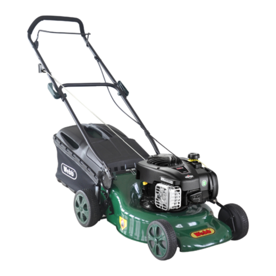
- Page 1 OPERATOR’S MANUAL AND PARTS LIST PETROL LAWNMOWER WER18HP Spares & Support: 01793 333212 www.webblawnmowers.co.uk Before use please read & understand this manual, paying particular attention to the safety instructions. 29/10/2013...
-
Page 2: Table Of Contents
To ensure that you get the best results from your petrol lawnmower please read all of these safety and operating instructions carefully before using this product. TABLE OF CONTENTS PRODUCT SPECIFICATION Product Specifications……………………...1 Safety Rules……………………………...2-3 Model number WER18HP Assembly/Pre-Operation…………………3-4 Petrol engine B&S 450E series 148cc Operation…………………………………4-6 Engine speed 2800rpm Maintenance……………………………...6-7... -
Page 3: Safety Rules
1. GENERAL OPERATION AND SAFETY RULES Read the instructions carefully. Be familiar with the controls and the proper use of the equipment. Do not put your hands or feet near or under rotating parts. Keep clear of the discharge opening at all times. -
Page 4: Assembly/Pre-Operation
Never tamper with safety devices. Regularly check that they are operating properly. Keep the machine free of grass, leaves, or other debris build-up. Clean oil or fuel spillage. Allow the machine to cool before storing. Exercise extreme caution when changing direction on slopes. Never attempt to make wheel height adjustments while the engine is running. -
Page 5: Operation
SET UP YOUR MOWER IMPORTANT: Unfold the handle carefully so as not to pinch or damage the control cables. 1. Depress the Operator Presence Control Bar (OPC) and raise the handles until the lower handle section locks into place at the mowing position. 2. - Page 6 IMPORTANT: Check the oil level before each use. Add oil if needed. Fill to the full line on the dipstick. Change the oil after every 25 hours of operation or each season. You may need to change the oil more often under dusty, dirty conditions. See “TO CHANGE ENGINE OIL” in the Maintenance section of this manual.
-
Page 7: Maintenance
MOWING TIPS Under certain conditions, such as very tall grass, it may be necessary to raise the height of the cut to reduce the pushing effort and to keep from overloading the engine and leaving clumps of grass clippings. It may also be necessary to reduce ground speed and/or run the lawnmower over the area a second time. -
Page 8: Storage
Remove the transmission casing by removing the screws and clean around the transmission and drive belts with a brush or compressed air once or twice a year. Once every season, the drive wheels should be cleaned internally. Remove both wheels. Clean the gear wheel and the wheel gear rim of grass and dirt using a brush or compressed air. -
Page 9: Symbols
SYMBOLS The following symbols can be found on the machine to remind you of the care and attention that are required during use. The symbols mean: Important: Read the instruction manual Warning! Beware of objects being thrown out. before using your lawn mower Ensure bystanders are at a safe distance. -
Page 10: Parts Diagrams And Lists
PARTS DIAGRAMS AND LISTS - HANDLE ASSEMBLY Item Part Item Part Description Description Number Number WE113-1 Foam Handle Cover WE113-13 Quick Lock Handle WE113-2 Brake Lever WE113-14 Pin 6x20 Bolt for Quick Lock WE113-3 Triangle Knob WE113-15 Handle Lock for Quick Lock WE113-4 Top Handle WE113-16... - Page 11 PARTS DIAGRAMS AND LISTS - DECK ASSEMBLY Item Part Item Part Description Description Number Number WE113-24 Deck WE113-37 Hex Self-Tapping Screw M6x10 WE113-25 "O" Ring 11.2x2.65 WE113-38 Height Adjustment Spring WE113-26 Inlet WE113-39 Height Adjustment Rod Pipe Connector Nut WE113-27 WE113-40 R Pin 1.5x25 M12x1.25...
- Page 12 PARTS DIAGRAMS AND LISTS – FRONT AXLE ASSEMBLY Item No Part Number Description WE113-49 Front Axle WE113-50 Front Wheel WE113-51 Wheel Bearing WE113-52 Lock Nut M8 WE113-53 Wheel Trim...
- Page 13 PARTS DIAGRAMS AND LISTS – REAR AXLE ASSEMBLY Item No Part Number Description WE113-54 Rear Axle with Height Adjustment Handle WE113-55 Rear Axle Sleeve WE113-56 Rear Wheel WE113-51 Wheel Bearing WE113-52 Lock Nut M8 WE113-57 Rear Wheel Trim...
- Page 14 PARTS DIAGRAMS AND LISTS – GRASS COLLECTOR ASSEMBLY Item No Part Number Description WE113-58 Grass Box Frame WE113-59 Grass Box Top WE113-60 Filter Plate WE113-61 60L Grass Box Bag (Unbranded) WE113-62 Rear Discharge Cover WE113-63 Rear Discharge Cover Shaft WE113-64 Rear Discharge Cover Spring WE113-65 Lock Washer 6...
-
Page 15: Parts Diagrams And Lists
PARTS DIAGRAMS AND LISTS – BLADE ASSEMBLY Item No Part Number Description WE113-68 Blade Adapter WE113-69 18" Double Edge Blade WE113-70 Blade Washer WE113-71 50mm Hex Flange Bolt... -
Page 16: Doc
80.5dB (A) - Page 17 GUARANTEE This product is guaranteed against manufacturing defects for a period of 24 months. This does not cover the product where the fault is due to misuse, abuse, use in contravention of the instructions, or where the product has been the subject of unauthorised modifications or alterations.
- Page 18 • • • • & & • • • • & & • • • •...
Need help?
Do you have a question about the WER18HP and is the answer not in the manual?
Questions and answers