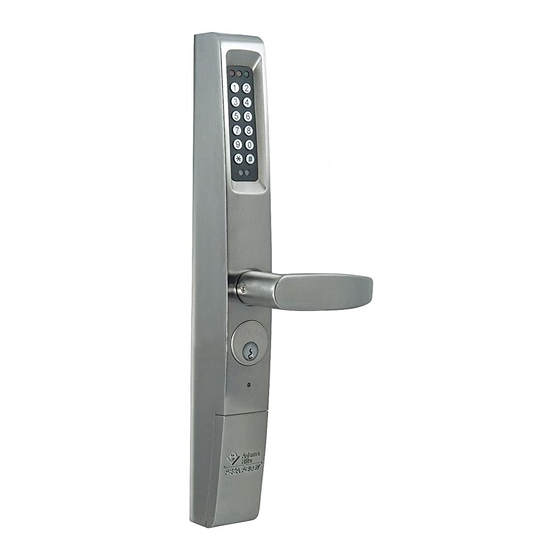
Assa Abloy 3090 Installation Instructions Manual
Hide thumbs
Also See for 3090:
- Owner's manual and user's manual (14 pages) ,
- Installation instructions and user manual (8 pages)
Advertisement
Quick Links
®
eForce
150 Keyless Entry
Installation
Instructions
Model 3090
Adams Rite Manufacturing Co.
260 Santa Fe Street
Pomona, CA 91767
Phone: 800-872-3267
Adams Rite Manufacturing Co.
Fax: 800-232-7329
260 Santa Fe Street
www.adamsrite.com
Pomona, CA 91767
Phone: 800-872-3267
www.adamsrite.com
Advertisement

Subscribe to Our Youtube Channel
Summary of Contents for Assa Abloy 3090
- Page 1 ® eForce 150 Keyless Entry Installation Instructions Model 3090 Adams Rite Manufacturing Co. 260 Santa Fe Street Pomona, CA 91767 Phone: 800-872-3267 Adams Rite Manufacturing Co. Fax: 800-232-7329 260 Santa Fe Street www.adamsrite.com Pomona, CA 91767 Phone: 800-872-3267 www.adamsrite.com...
- Page 2 Adams Rite Manufacturing Co. (hereinafter ADAMS RITE) manufactures its products in a manner to be free of defects. Should any defect of manufacture (in material or workmanship) occur in its products, ADAMS RITE, upon prompt notification and proof to its satisfaction that the product was defective in manufacture for the use intended by ADAMS RITE, will at its option, ex- change the product, repair the defect or refund the price charged by ADAMS RITE, FOB factory based on the following schedule:...
- Page 3 Table of Contents Table of Contents Installation Tools & Equipment ............5 Door Preparation ................6 Spindle Preparation ................7 Lock Series Configuration..............8 ® Handing the eForce ............... 10 Mortise Cylinder Installation............. 11 ® Mounting the eForce ..............12 Battery Installation ................
- Page 4 ® Battery installation eForce Properly insert 4 (AA) Alkaline bat- teries into battery holder observing the polarity markings. ® Plug battery pack into eForce connector (F . 19). Lithium batteries are suggested in climates reaching 20°F and below. . 19 ®...
- Page 5 Mounting the eForce INSTALLATION TOOLS & EQUIPMENT Insert the properly dimensioned spin- IMPORTANT NOTES: dle into the output hub. The 3090-01 is designed exclusively for latching hardware including: ® Mount eForce 150 onto mounting Adams Rite 4500/4900 Deadlatches; bracket and guide spindle into Cam Adams Rite 8000 Series Exit Devices;...
- Page 6 Handle with care. Do not over-tighten! Do not use Dummy Cylinder! Remote Switch Kit RSK-3090 (Optional) For applications that require a remote activation switch, plug the RSK-3090 into the board as shown in Fig. 15 & 16.
- Page 7 Insert Flat end into Proceed to step 5 if installing the exit devices 3090-02! For Adams Rite 8600 Concealed Vertical Rod Exit Devices: Snap-off spindle at sixth (6th) notch as shown in F .5. For 2” thick doors add two notches.
- Page 8 STEP 3 CONFIGURE FOR LOCK SERIES RIM Exit Device Application: 3090-01 for 8700/8800 Mortise Latch Application: 3090-01 for 4500/4900 On the back side of the exit device, remove only (including 8300/8400 Exit Devices) the lower Phillips head screw, depending on hand of door, to free up the cylinder actuator for use.


Need help?
Do you have a question about the 3090 and is the answer not in the manual?
Questions and answers