Table of Contents
Advertisement
Advertisement
Table of Contents

Related Manuals for Coway CHP-671R/L


Summary of Contents for Coway CHP-671R/L
- Page 1 CHP-671R/L...
-
Page 3: Table Of Contents
Table of Contents 1. Product characteristics and specifications Product characteristics ..................1-1 1-1-1 Major Part Characteristics ..............1-2 Specifications ....................1-3 2. Product installation Installation method ...................2-1 2-1-1 Precautions on installation ..............2-1 2-1-2 Installing the product ................2-2 How to use .......................2-5 3. Disassembling and reassembling Disassembling and reassembling the product ..........3-1 3-1-1 Draining water before disassembling the product ........3-1 3-1-2 Cover-top ASSY separation ..............3-2... - Page 4 Table of Contents 6. Parts location diagrams Electrical wiring diagram ..................6-1 Water piping diagram ..................6-2 PBA location diagram ..................6-3 6-3-1 MAIN PBA ....................6-3 6-3-2 FRONT PBA ..................6-6 6-3-3 SMPS PBA ...................6-7 7. Reference information Names of each part ..................7-1 Functions and reference information ...............7-3 7-2-1 Explanation of operation and indication parts (...
-
Page 5: Product Characteristics And Specifications
Mass gutter applying It doesn’t need the extra secondary draining tank as it applies the mass gutter and it is convenient as it can extract the room water with a big vessel directly. Coway co., Ltd... -
Page 6: Major Part Characteristics
Operates the NOS valve to cut off room-temperature water when the water principles overflow sensor detects an overflow in the room-temperature water tank. Major Part Characteristics Parts Standard ratings and specifications Remarks • Volts : DC 24 V Feed Valve / NOS Valve • AMPS : 210 mA Compressor • Refer to the rating plate. Coway co., Ltd... -
Page 7: Specifications
The water tank capacity is the amount by the size and can be different from the extraction capacity. Without any prior notice, all or parts of the product are subject to change for the purpose of improving the performance of the product. Refer to Performance data sheet for individual contaminants, reduction performance and general operating information. Coway co., Ltd... - Page 8 MEMO Coway co., Ltd...
-
Page 9: Product Installation
- Plus sediment filter: I nstall after washing with source water for about 10 seconds. - Pre-carbon filter: I nstall in reverse and install after washing with source water for about 3 minutes. - Membrane (RO) filter: I nstall the filtered water valve after washing with source water for about 5 minutes. - Nanotrap (R) filter: I nstall after washing with source water for about 3 minutes. - Plus Inno-Sense filter: Install with no separate flushing. - Plus Inno-Sense filter (D): Install with no separate flushing. Installation • The source water pressure must be at least 138 kPa for the water volume and water pressure water system to operate smoothly. • Source water pressure of 138 kPa or less: Install within a height of 3 m and a distance of 5 m. Installation distance • Source water pressure of 138 kPa or more: Install within a height of 3 m and a distance of 25 m. Coway co., Ltd... -
Page 10: Installing The Product
Product installation 2-1-2 Installing the product The summary for the proper installation of the water filtration device Explanation Reference picture 1. Close main water supply valve to separate the faucet. 2. Apply the teflon tape on the adaptor and fit it to the pipe. • Do not turn the water pipe. 3. Connect the faucet with the adaptor. • Install the adaptor with connector to the cold water pipe. 4. Connect 1/4 inch orange tubing with the connector on the adaptor. • Flush water through each filter at least 5 minutes before Connection. Coway co., Ltd... - Page 11 Product installation Explanation Reference picture 5. Open the feed valve to supply water to the filtration system. Coway co., Ltd...
- Page 12 Follow the instruction for installation Main water supply valve Voltage rating that matches it on the rating plate. Connect the orange color inlet tubing to the tap water supplying pipe. Connect the outlet tubing Inlet tubing (Orange) Outlet tubing(Blue) Coway co., Ltd...
-
Page 13: How To Use
Product installation 2-2 How to use Only connect the power cord to the voltage rating that matches it on the rating plate. To drink the cold water Explanation Reference picture 1. You can drink the cold water when you turn the jog shuttle to the right in cold water/room water changeover faucet and pushing the cup-touch lever. • If the cold water doesn’t come from the water filtration device, check if the cold water mode indicator is turned on. Coway co., Ltd... - Page 14 Product installation To drink the hot water Explanation Reference picture 1. If you press the hot water safety button and push the cup- touch lever, you can drink the hot water. • If the cold water doesn’t come from the water filtration device, check if the cold water mode indicator is turned on. Coway co., Ltd...
- Page 15 Product installation To drink the room water Explanation Reference picture 1. You can drink the room water when you turn the jog shuttle to the left in cold water/room water changeover faucet and push the cup-touch lever. Coway co., Ltd...
- Page 16 MEMO Coway co., Ltd...
-
Page 17: Disassembling And Reassembling
Description Reference picture Drain hose 1) Push the drain hose with your hand to open. 2) Open the drain connector cap. 3) Open the drain connector cap. 4) Connect the drain hose and then completely drain water. Coway co., Ltd... -
Page 18: Cover-Top Assy Separation
Disassembling and refitting 3-1-2 Cover-top ASSY separation Part name Description Reference picture Cover-top 1) Remove the cover-top in the direction of the arrow. 2) Remove the silicon hose - overheating. Coway co., Ltd... - Page 19 Description Reference picture Cover-top 3) Detach the 6 clips for the cap-main tank ASSY. 4) Remove the anti-bacterial filter ASSY in the direction of the arrow. 5) Remove the separator ASSY in the direction of the arrow. Coway co., Ltd...
-
Page 20: Cover-Front Lower Assy Separation
1) Push the drain hose with your lower ASSY hand to open. 2) Remove the 1 screw from the cover-front lower ASSY. : M 4X10 3) Remove the cover-front lower ASSY in the direction of the arrow. Coway co., Ltd... - Page 21 1) Use a ‘-’ screwdriver to remove fittings connected to the filter. 2) Remove the filter in the direction of the arrow. Tray 1) Remove the tray in the direction of the arrow. 2) Remove the grill-tray in the direction of the arrow. Coway co., Ltd...
-
Page 22: Cover-Front Upper Assy Separation
ASSY in the direction of the arrow. Change the deco-multifaucet ASSY to the cold water location and then remove. Assemble the cover-front ASSY. Do not detach the deco-multifaucet ASSY. 3) Remove connectors connected to the cover-front upper ASSY. Coway co., Ltd... - Page 23 Reference picture PBA-front 1) Remove the 2 screws from the ASSY cover-front PBA. : 2-THT 4X12 2) Remove the PBA-front ASSY in the direction of the arrow. Deco- 1) Push the deco-multifaucet ASSY multifaucet hook to detach. ASSY Coway co., Ltd...
-
Page 24: Pba Assy Separation
2) Remove all connectors connected to the PBA ASSY. 3) Remove the 2 screws from the case-PBA main ASSY. : 2-THT 4X10 4) Remove the 2 screws from the PBA-main. : 2-THT 4X10 Coway co., Ltd... - Page 25 Sensor- 1) Use a ‘-’ screwdriver to remove the capacitance fittings. water level 2) Use a ‘-’ screwdriver to remove the sensor-capacitance water level clip. 3) Remove the sensor-capacitance water level in the direction of the arrow. Coway co., Ltd...
- Page 26 1) Use a ‘-’ screwdriver to remove purified hoses connected to the faucet-cold purified water. 2) Remove the 2 screws from the faucet-cold purified water. : 2-THT 4X12 3) Remove the faucet-cold purified water in the direction of the arrow. 3-10 Coway co., Ltd...
- Page 27 1) Remove the 2 screws from the water ASSY faucet-hot water ASSY. : 2-THT 4X12 2) Remove the faucet-hot water ASSY in the direction of the arrow. Bracket- 1) Remove the 2 screws from the faucet bracket-faucet. : 2-THT 4X10 Coway co., Ltd 3-11...
- Page 28 2) Remove the sensor-cold water temperature sensor in the direction of the arrow. Connector- 1) Open the drain connector cap. drain ASSY 2) Use needle-nose pliers to turn and remove the connector drain ASSY in the direction of the arrow. 3-12 Coway co., Ltd...
- Page 29 1) Use a ‘-’ screwdriver to remove NOS ASSY fittings connected to the valve- feed/NOS ASSY. 2) Remove the 1 screw from the valve-feed/NOS ASSY. : THT 4X12 Bracket-filter 1) Remove the 2 screws from the bracket-filter. : 2-THT 4X10 Coway co., Ltd 3-13...
-
Page 30: Cover-Rear Assy Separation
1) Remove the 6 screws from the cover-rear. : 4-THT 4X10 (◯) : 2-PHT 6X18 (◯) Power cord 1) Remove the 1 screw from the power cord. : PHT 3X8 (washer) 2) Remove the power cord in the direction of the arrow. 3-14 Coway co., Ltd... - Page 31 Disassembling and refitting Part name Description Reference picture Cover-side 1) Remove the 8 screws from the ASSY cover-side L ASSY. : 8-THT 4X10 2) Remove the 8 screws from the cover-side R ASSY. : 8-THT 4X10 Coway co., Ltd 3-15...
- Page 32 MEMO 3-16 Coway co., Ltd...
-
Page 33: Fault Diagnosis
Connector contact malfunction Connect connector properly contact normal? Check SMPS output voltage Check and replace SMPS DC 24 V, DC 5 V Is the MAIN PBA MAIN PBA connector contact Replace and check MAIN PBA connector contact normal? malfunction Coway co., Ltd... - Page 34 Fault diagnosis Is the FND cable FND cable access malfunction Check and replace FND cable connection OPEN? Is the PBA MICOM PBA power circuit malfunction Check and replace MAIN PBA voltage DC 5 V? Coway co., Ltd...
-
Page 35: Cooling Malfunction
Is there anything water temperature display wrong with the cold lamp flashing? water connector? Check cold water sensor measured value and then replace if faulty COMP Main/auxiliary wire wound COMP. Is the COMP. Replacement resistance 0 Ω or ∞ malfunction resistance normal? Coway co., Ltd... - Page 36 Normal if OLP current flows Are the OLP and PTC normal? Check and replace PTC 22 Ω normal COMP. While COMP. COMP. 0 V malfunction when Check and replace MAIN PBA is operating, Is the supplied power checking connector rated voltage? Coway co., Ltd...
-
Page 37: Hot Water Malfunction
Is the FND hot water Is the hot water temperature display connector normal? lamp flashing? Replace hot water sensor Hot water tank temperature Is the hot water Check and replace measurement and temperature temperature sensor normal? hot water sensor table comparison Coway co., Ltd... - Page 38 Check and replace heater 88 Ω + 1.5 % - 8 %? resistance is 0 Ω, ∞ Is the bimetal normal? Bimetal current flow normal Check and replace bimetal Is the voltage supplied Faulty MAIN PBA Check and replace MAIN PBA to the heater rated voltage when the heater is on? Coway co., Ltd...
-
Page 39: Room Temperature Water Malfunction And Water Overflow Malfunction
Are the water pipes Check source water entry/waste connected according to water and water pipes specifications? SMPS voltage Is the SMPS secondary Check and replace after verifying DC 24 V, DC 5 V voltage normal? Coway co., Ltd... - Page 40 - 0 V water level sensor when the sensor detects the area, 5 V when not detected. Feed/NOS valve when room- Is the MAIN PBA temperature water conditions are Check and replace MAIN PBA valve voltage normal? normal: DC 24 / 0 volts Coway co., Ltd...
-
Page 41: Control Specifications
• FND display status (initial power connection status) - Hot water temperature display (refer to hot water setting mode) - Cold water temperature display (refer to cold water setting mode) - Water level display (low water, medium water, full water) Coway co., Ltd... - Page 42 - Heater output is turned OFF after the HOT selection switch is OFF. - FND display status → H1/H2/H3 kept off • FND display control specifications according to hot water temperature are as follows. - ON/OFF control specifications according to the HOT segment's temperature are as follows. HOT Segment 94 °C (16.302 kΩ) 80 °C (26.13 kΩ) 79 °C (27.06 kΩ) 74 °C (32.292 kΩ) Always ON - Temperature detection range: 1.2 MΩ ~ 13 kΩ 4-10 Coway co., Ltd...
- Page 43 H1/H2/H3 flash on the display. • If the compressor and heater operate at the same time, they must operate at Compressor, 1 second intervals. heater differential control function • Hot water temperature thermistor model: MMT-0.4B Other • Thermistor temperature detection error range: ± 0.5 °C or less • The hot water temperature sensing circuit's partial pressure resistance is D grade (0.5 %). • The hot water temperature is checked 100 times and, if it is within a set range at those 100 times, the temperature is detected as normal. • Hot water temperature detection range: 1.2 MΩ ~ 13 kΩ Coway co., Ltd 4-11...
- Page 44 - The COOL function is turned off if the COOL selection switch is pressed and held (1s or more). - Compressor output is turned OFF after the COOL selection switch is OFF for 1 second. - FND display status → C1/C2/C3 kept OFF 4-12 Coway co., Ltd...
- Page 45 1 second delay. • If the cold water temperature sensor is operating normally, the FND display and compressor operate according to water level and cold water temperature. The compressor starts 5 minutes after the point at which it had stopped. • If the compressor and heater operate at the same time, they must operate at Compressor, 1 second intervals. heater differential control function Coway co., Ltd 4-13...
- Page 46 • After the compressor's output is OFF for 5 minutes, it restarts according to cold water temperature control specifications. - When the cold water temperature control specifications are ON temperature (7.8 °C) or more, the compressor starts. - If the cold water temperature control specifications are between ON temperature (7.8 °C) and OFF temperature (5.7 °C), the compressor does not start. 4-14 Coway co., Ltd...
- Page 47 The above data may vary depending on the method of calculation with figures by simple computation. - Temperature detection resistance range: 163 kΩ ~ 13 kΩ • Cold water temperature thermistor model: MLT-50B Other • Thermistor temperature detection error range: ± 0.5 °C or less • The cold water temperature sensing circuit's partial pressure resistance is D grade (0.5 %). • The cold water temperature is checked 100 times and, if it is within a set range at those 100 times, the temperature is detected as normal. • Cold water temperature detection range: 0 °C ~ 55 °C (≒ 163 kΩ ~ 15 kΩ) Coway co., Ltd 4-15...
- Page 48 - Dual water level error: ( Low water/medium water/full water) error + water overflow error, low water + medium water FND (L1 + L2) 0.5 second ON/OFF periodic flashing. L3 FND is off. - If water overflow is detected 3 times or more, an overflow-related error is indicated on the display and the related valve stops operating. 4-16 Coway co., Ltd...
- Page 49 Detected Detected detected detected The #10 error is displayed when it occurs 3 times in total and operation is normal if over/full water level is canceled. Even 3 times in total can be cleared. Coway co., Ltd 4-17...
- Page 50 • Cold water/hot water/water level upper bar flashes → upper + middle flashes → upper + middle + lower flashes → upper + middle flashes, upper bar flashing repeats twice. • If test mode is active, the delay time of 5 minutes for compressor restarting is canceled. • The heater starts 1 second after compressor operation in the heater, compressor differential control function. • Water overflow detection delay time (20 seconds) and water level detection delay time change to 1 second • In test mode, the compressor operates at less than low water level when the compressor is ON • If power is reconnected or 30 minutes elapses after test mode operation, test mode is canceled and normal mode is entered. 4-18 Coway co., Ltd...
- Page 51 HEATER control temperature according to temperature LEVEL is as follows. HOT LEVEL Heater OFF Heater ON Remarks Stage 3 H1/H2/H3 94 °C (16.302 kΩ) 80 °C (26.13 kΩ) [Korean flashing temperature] H1/H2 flashing 90 °C (18.599 kΩ) 85 °C (22.003 kΩ) Stage 2 H1 flashing 84 °C (22.766 kΩ) 79 °C (27.060 kΩ) Stage 1 Coway co., Ltd 4-19...
- Page 52 LEVEL. • If the temperature LEVEL setting mode is entered after the temperature LEVEL is changed, the saved temperature LEVEL is displayed. • If 15 seconds elapses after the temperature LEVEL setting function operates, the temperature LEVEL setting function is canceled and normal mode is entered. Each time the key is pressed, there is an additional 15 second delay. 4-20 Coway co., Ltd...
- Page 53 MEMO Coway co., Ltd 4-21...
-
Page 54: Exploded View And Parts List
Exploded view and parts list 5. Exploded view and parts list 5-1 Exploded view and parts list This document is Coway’s technical property. Only the person approved by the company may use this document. Coway co., Ltd... -
Page 55: Parts List
DECO-MULTI FAUCET ASSY FAUCET-COLD ROOM WATER BRACKET-FAUCET COVER-FRONT PBA CASE-MAIN PBA ASSY VALVE-FEED-NOS SEDIMENT FILTER-PLUS 14INCH PRE-CARBON FILTER-14INCH MEMBRANE FILTER-RO 14INCH INNO-SENSE FILTER-PLUS 14INCH VALVE-DRAIN CONTROL ELBOW BRACKET-FILTER COVER-TOP CAP-MAIN TANK ASSY SEPARATOR ASSY COOLING COIL ASSY Coway co., Ltd... - Page 56 Low water level SENSOR-COLD WATER THERMAL INSULATION-MAIN TANK A BRACKET-HEATING TANK ASSY CONNECTOR-COLD WATER DRAIN ASSY CONNECTOR-HOT WATER DRAIN ASSY HEATING TANK ASSY COMPRESSOR ASSY PLATE-BASE DW ASSY COVER-REAR CONDENSER-WIRE ASSY COVER-REAR COVER-SIDE L ASSY COVER-SIDE R ASSY Coway co., Ltd...
-
Page 57: Parts Location Diagrams
Parts location diagrams 6. Parts location diagrams 6-1 Electrical wiring diagram This document is Coway’s technical property. Only the person approved by the company may use this document. CHP-671R Display PBA HOT Water Thermistor COLD Water Debug Thermistor CN16... -
Page 58: Water Piping Diagram
Feed Water Cooling tank Feed Water Cool/Room Water Water Heating Cool/Room tank Water Water Heating tank Reject Water supply Valve Reject Water Reject Water supply Valve Reject Water Hot Water Cool/Room Drain Drain Hot Water Cool/Room Drain Drain Coway co., Ltd... -
Page 59: Pba Location Diagram
6-3-1 MAIN PBA 1 CN16 2 CN19 3 CN15 SMPS AC IN COMP. Pin No. Signal Pin No. Signal Voltage rating that matches it on the + 5 V rating plate. + 24 V + 24 V Coway co., Ltd... - Page 60 + 5 V SIGNAL SIGNAL SIGNAL 0 CN6 ! CN4 @ CN1 LEVEL SENSOR (OVER) COOL SENSOR COOL SENSOR Pin No. Signal Pin No. Signal Pin No. Signal SIGNAL + 5 V + 5 V SIGNAL SIGNAL Coway co., Ltd...
- Page 61 Parts location diagrams # CN2 DISPLAY Pin No. Signal SIGNAL SIGNAL1 (SOURCE) SIGNAL2 (SOURCE) SIGNAL3 (SOURCE) SIGNAL4 (SOURCE) SIGNAL5 (SOURCE) SIGNAL6 (SOURCE) SIGNAL1 (SINK) SIGNAL2 (SINK) SIGNAL3 (SINK) SIGNAL4 (SINK) + 5 V Coway co., Ltd...
-
Page 62: Front Pba
Parts location diagrams 6-3-2 FRONT PBA 1 CN1 DISPLAY Pin No. Signal Pin No. Signal SIGNAL SIGNAL1 (SINK) SIGNAL2 (SINK) SIGNAL1 (SOURCE) SIGNAL3 (SINK) SIGNAL2 (SOURCE) SIGNAL4 (SINK) SIGNAL3 (SOURCE) + 5 V SIGNAL4 (SOURCE) SIGNAL5 (SOURCE) SIGNAL6 (SOURCE) Coway co., Ltd... -
Page 63: Smps Pba
SMPS PBA 1 CN2 2 CN1 OUT PUT - MAIN PBA AC IN Pin No. Signal Pin No. Signal Voltage rating that matches it on the + 5 V rating plate. + 24 V + 24 V Coway co., Ltd... - Page 64 MEMO Coway co., Ltd...
-
Page 65: Reference Information
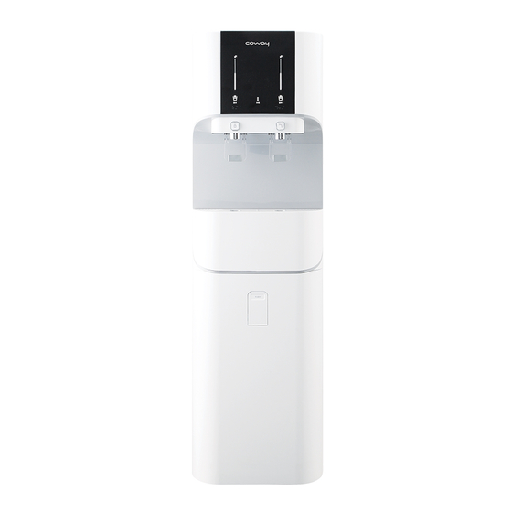
Reference information 7. Reference information 7-1 Names of each part Front Indicators Cold / Room water Changeover Faucet Hot water Faucet Cup-touch Lever Gutter Front Draining Door Front Cover Coway co., Ltd... - Page 66 Reference information Rear Top Cover Rear Cover Power Cord Inlet(Orange) Outlet (Blue, CHP-671R/L) Coway co., Ltd...
-
Page 67: Functions And Reference Information
Cold water The indicator is turned on according to the cold water temperature temperature. The more light, the colder the water. indicator Hot water mode When you select hot water mode, the indicator is turned indicator Coway co., Ltd... - Page 68 Basically, one bar is turned on. Operation part Name Explanation Hot water mode Press to select/deselect hot water mode. selection button Cold water mode selection Press to select/deselect cold water mode. button Coway co., Ltd...
- Page 69 When you are using the product for the first time, or if the hot water feature is off for a long time, then it takes about 30 minutes for the water to reach a preset hot water temperature. Coway co., Ltd...
-
Page 70: Types And Functions Of Filters
The nanotrap (R) filter removes particulates from water and selectively filters out Function microorganisms, bacteria, viruses, etc. Filter name Plus-Innosense filter Material Polyethylene + activated carbon, polysulfone Function The Plus-Innosense filter removes odorous materials and improves water taste. Coway co., Ltd... -
Page 71: Water Filtration Process
Reference information 7-2-3 Water Filtration Process The 5-step water filtering system (CHP-671R/L) STEP 1 PLUS-SEDIMENT FILTER This plus sediment filter has the functions to remove infusible particles from feed water and to protect membrane and pre-carbon filter from being plugged. - Page 72 Reference information ANTIBACTERIAL FILTER Reject Water Outlet PLUS SEDIMENT PRE-CARBON RO MEMBRANE PLUS INNO-SENSE ANTIBACTERIAL FILTER FILTER FILTER FILTER FILTER Uses of reject water • The reject water should be used for cleaning the restroom, the house, clothes, or purposes other than drinking. • Never use the reject water for a drinking or cooking. Coway co., Ltd...
- Page 73 MEMO Coway co., Ltd...
- Page 74 MEMO 7-10 Coway co., Ltd...
Need help?
Do you have a question about the CHP-671R/L and is the answer not in the manual?
Questions and answers