Table of Contents
Advertisement
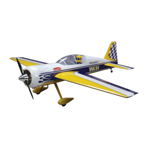
Specifications
Wingspan .......................................89 in (226.1mm)
Length w/Spinner ...........................84 in (213.4mm)
Wing Area ..........................1434 sq in (92.8 sq dm)
Flying Weight ................ 16.75–18.5 lb (7.6–8.4 kg)
YAK 54
Assembly mAnuAl
Engine Size .......................................... 45–60cc gas
Radio......................................... 4-channels or more
Servos .........................................................6 servos
Hardware Included ..............................................Yes
89"
Advertisement
Table of Contents

Related Manuals for Hangar 9 YAK 54 89


Summary of Contents for Hangar 9 YAK 54 89
- Page 1 YAK 54 89" Assembly mAnuAl Specifications Wingspan ........89 in (226.1mm) Engine Size .......... 45–60cc gas Length w/Spinner ......84 in (213.4mm) Radio......... 4-channels or more Wing Area ......1434 sq in (92.8 sq dm) Servos ............6 servos Flying Weight ....16.75–18.5 lb (7.6–8.4 kg) Hardware Included ..........Yes...
-
Page 2: Table Of Contents
Table of Contents Using the Manual ..............3 Required Tools and Adhesives . -
Page 3: Using The Manual
Before Starting Assembly Before beginning the assembly of the YAK 54 89-inch, remove each part from its bag for inspection. Closely inspect the fuselage, wing panels, rudder, and stabilizer for damage. If you find any damaged or missing parts, contact the place of purchase. -
Page 4: Radio And Power Systems Requirements
Radio and Power Systems Requirements • 7-channel computer radio system (minimum) w/receiver • Large Servo Arms (JRPA236) (4 pkgs) • 24-Inch Servo Extension (JRPA102) (2) • JR Charge Jack Switch (JRPA004) • JR Deluxe Switch (JRPA001) (1) • 9-Inch Servo Extension (JRPA097) (3) •... -
Page 5: Warranty Period
Warranty Period Exclusive Warranty- Horizon Hobby, Inc., (Horizon) warranties that the Products purchased (the "Product") will be free from defects in materials and workmanship at the date of purchase by the Purchaser. Limited Warranty (a) This warranty is limited to the original Purchaser ("Purchaser") and is not transferable. REPAIR OR REPLACEMENT AS PROVIDED UNDER THIS WARRANTY IS THE EXCLUSIVE REMEDY OF THE PURCHASER. -
Page 6: Questions, Assistance, And Repairs
Questions, Assistance, and Repairs Your local hobby store and/or place of purchase cannot provide warranty support or repair. Once assembly, setup or use of the Product has been started, you must contact Horizon directly. This will enable Horizon to better answer your questions and service you in the event that you may need any assistance. -
Page 7: Safety, Precautions, And Warnings
Safety, Precautions, and Warnings This model is controlled by a radio signal that is subject to interference from many sources outside your control. This interference can cause momentary loss of control so it is advisable to always keep a safe distance in all directions around your model, as this margin will help to avoid collisions or injury. -
Page 8: Aileron Servo Installation
Aileron Servo Installation Required Parts Step 2 • Wing panel (left and right) Attach a 12-inch (305mm) extension to the aileron servo • Control horn (2) lead. Use thread or a comercially available connector to make sure the extension and lead do not unplug •... - Page 9 Step 4 Step 6 Use the servo hardware to mount the aileron servo in the With the radio system still on, install the 2-inch (51mm) wing. The output shaft of the servo will face toward the control turnbuckle between the control horn and ball link. control horn.
-
Page 10: Rudder And Rudder Servo Installation
Rudder and Rudder Servo Installation Required Parts Step 2 • Fuselage • Rudder Place the rudder in position against the fuselage. Use a • Rudder hinge wire • Control horn (2) drill when installing the hinge, as it will help guide the hinge wire through the hinges. - Page 11 Step 4 Step 6 Hold the tail wheel tiller arm on the bottom of the rudder. Apply a few drops of foam-safe CA into each hole to With the tiller as far forward as possible, use a felt-tipped harden the surrounding wood.
- Page 12 Step 8 Step 10 Attach the tail gear to the fuselage using two 4-40 x Use a hobby knife to remove the covering from the 1/2-inch socket head screws and two #4 washers. openings for the rudder control cables. ...
- Page 13 Step 12 Step 14 Prepare two ball ends by threading a cable end into each Install the rudder servo in the fuselage with the output of of the ball ends as shown. the servo facing to the front. Hint: Use a pin drill and 1/16-inch (1.5mm) drill bit to predrill the holes for the servo ...
-
Page 14: Tail Mounted Servo Installation
Tail Mounted Servo Installation Required Parts Step 1 • Fuselage • Servo A servo can be mounted in the rear of the fuselage when • Pro-Link • Ball end w/hardware using heavier engine options. You will need to remove the covering for the servo and mount the servo using the Required Tools and Adhesives hardware provided with the servo. - Page 15 Hint: Use a pin drill and 1/16-inch (1.5mm) Step 4 drill bit to predrill the holes for the servo With the radio system still on, install the 2-inch (51mm) mounting screws. This will prevent the wood control turnbuckle between the control horn and ball link. from splitting when installing the servo.
- Page 16 o Step 7 Step 9 Secure a 24-inch (610mm) servo extension to the elevator Repeat Steps 7, 8 and 6 in that order to install the servo. Slide the tube into the fuselage while guiding the remaining stabilizer in position. extension into the fuselage toward the radio area.
-
Page 17: Landing Gear Installation
Landing Gear Installation Required Parts Step 2 • Fuselage • Landing gear Remove the landing gear fairing from the bottom of • Axles w/nut (2) • #8 lock washer (4) the fuselage. • #8 washer (4) • #4 washer (4) •... - Page 18 Step 5 Step 7 Place the landing gear fairing back onto the fuselage and Attach the wheels to the landing gear using two 5/32-inch secure it using the screws removed in Step 2. wheel collars and two setscrews for each wheel. The wheel collars are positioned on either side of the wheel.
- Page 19 Step 9 Step 11 Use a felt-tipped pen to transfer the position for the two Install two 4-40 blind nuts inside the wheel pant. mounting screws onto the wheel pant. Step 12 Step 10 Secure the wheel pant to the landing gear using two Use a drill and 1/8-inch (3mm) drill bit to drill the two 4-40 x 1/2-inch socket head screws and two #4 washers.
-
Page 20: Engine Installation
Important: Make sure to use Step 13 threadlock on the setscrews to prevent Loosen the setscrews and position the wheel in the center them from vibrating loose. of the opening of the wheel pant. Tighten the setscrews to secure the position of the wheel. ... - Page 21 Step 2 Step 4 Refer to the engine centerline marked on the firewall and Attach the engine to the firewall using four 1/4-20 bolts center your engine on these marks. Measure the distance and four 1/4-inch split washers from the inside of the between the standoff mounts, both horizontal and vertical.
- Page 22 Step 6 Step 7 Cut an oval-shaped opening in the bottom of the fuselage Install the supplied canister mount into the area in front behind the fuel tank. Use a covering iron to seal the of the fuel tank. Assemble the canister and header using UltraCote into the fuselage.
- Page 23 Step 10 Cut out the cowling as shown to clear the exhaust and spark plug cap. Step 8 Position the exhaust stinger directly down so the exhaust exits the aircraft. Bolt the exhaust header to the engine. Step 11 ...
- Page 24 Step 12 Step 13 Glue the throttle servo mount in place. Position the throttle Install the ignition and ignition battery onto the engine box servo toward the side of the fuselage that is appropriate as shown. Mounting the ignition to the engine box keeps for the engine being used.
-
Page 25: Radio Installation
Radio Installation Required Parts Step 2 • Fuselage • Switch (3) Mount the switch for the ignition toward the front of the • 8-32 x 1 -inch socket head screw (4) fuselage as shown. Required Tools and Adhesives • Drill •... - Page 26 Step 4 Step 5 Place a piece of foam between the radio tray and receiver Using double-sided foam tape, (servo tape) mount the and secure it inside the fuselage. Make the connections remote receiver(s) keeping the remote antenna(s) at least from the rudder, elevator and throttle servos, as well as the 2 inches away from the primary antenna.
-
Page 27: Pilot And Canopy Installation
Pilot and Canopy Installation Required Parts Step 3 • Fuselage • Pilot figure Remove a section of the covering from the canopy hatch • Instrument panel decal • Canopy from under where the pilot will sit. Use 30-minute epoxy to secure the pilot in the cockpit. - Page 28 Step 5 Step 7 Use 400-grit sandpaper to lightly scuff the edges of the Secure the canopy hatch to the fuselage. canopy hatch and canopy where they will contact each other. Use a paper towel and rubbing alcohol to remove any residue or debris from both items.
-
Page 29: Control Throws
Control Throws Setting the control throws for your YAK 54 does require This is necessary to ensure that the mechanical advantage some attention to detail. To correctly set the throws, it is as great as possible. When setting up the Yak, or any is highly suggested to use the following procedure to model for 3D aerobatics, mechanical advantage is lower in achieve the greatest mechanical advantage from your... -
Page 30: Recommended Center Of Gravity (Cg)
Recommended Center of Gravity (CG) The center of gravity can also be measured at the wing tip An important part of preparing the aircraft for flight is properly balancing the model. This is especially important by measureing forward of the hinge line 3 -inch (95mm) when various engines are mounted. -
Page 31: Rates And Expos
Rates and Expos Use Expo to soften the feel of the model. On high 3D Use low rate settings for all flying except for 3D rates, use quite a bit of expo. The goal on 3D rates is to aerobatics. For precision flying or general sport hot- get the model to feel the same around neutral as it does dogging, the low rate throws are perfect, even for snap on low rates. -
Page 32: Preflight
Preflight Never attempt to make full throttle dives! For those of you who are veterans of large models, this is old news. But to you newcomers to the world of large Large models perform much more like full-size aircraft models, this is very important information. than small models. -
Page 33: Instructions For Disposal Of Weee By Users In The European Union
Instructions for Disposal of WEEE by Users in the European Union This product must not be disposed of with other waste. Instead, it is the user’s responsibility to dispose of their waste equipment by handing it over to a designated collection point for the recycling of waste electrical and electronic equipment. -
Page 34: 2008 Official Ama National Model Aircraft Safety Code
2008 Official AMA National Model Aircraft Safety Code GENERAL 8. I will not operate model aircraft carrying pyrotechnic devices which explode burn, or propel a projectile 1. A model aircraft shall be defined as a non-human- of any kind. Exceptions include Free Flight fuses or carrying device capable of sustained flight in the devices that burn producing smoke and are securely atmosphere. - Page 35 2008 Official AMA National Model Aircraft Safety Code Radio Control 7. With the exception of events flown under official AMA rules, no powered model may be flown outdoors closer 1. All model flying shall be conducted in a manner to than 25 feet to any individual, except for the pilot and avoid over flight of unprotected people.
- Page 36 © 2008 Horizon Hobby, Inc. 4105 Fieldstone Road Champaign, Illinois 61822 (877) 504-0233 horizonhobby.com 12654...
Need help?
Do you have a question about the YAK 54 89 and is the answer not in the manual?
Questions and answers