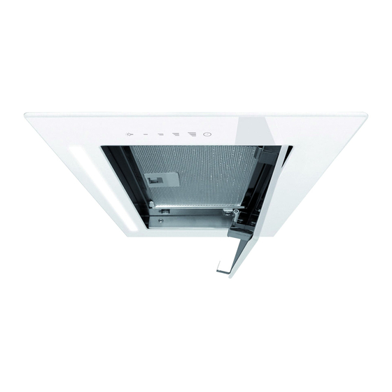
Schweigen KLS-9GLASS Installation Manual
Undermount
Hide thumbs
Also See for KLS-9GLASS:
- Instruction manual (28 pages) ,
- Instruction manual (33 pages) ,
- Instruction manual (25 pages)
Table of Contents
Advertisement
Quick Links
Advertisement
Table of Contents

Related Manuals for Schweigen KLS-9GLASS


Summary of Contents for Schweigen KLS-9GLASS
- Page 1 RANGEHOOD & INSTALLATION GUIDE Undermount Revision V1.3 Page 1 of 40...
-
Page 2: Table Of Contents
INDEX Before using this guide, please check our website www.schweigen.com.au to ensure you have the latest version. INDEX ........................... 2 1. WELCOME ........................4 2. YOUR SAFETY ........................ 5 Safety Advice ........................5 Before Installation ......................6 Product Use........................7 Maintenance and Service .................... - Page 3 Attaching the Computer Board (Certain models only) ............24 Installing the Undermount Rangehood (With hanging devices) ........25 Installation for GA-600S and GA-900S (No Visible Screws) ..........26 Installation for KLS-9GLASS and UM-PA9S ..............27 Installation for UM-B19S ....................28 Installing Basic GA (No Visible Screws) ................29 Regulating the Aventos Adjustable Hinge (only used with some models) ......
-
Page 4: Welcome
This will ensure your personal safety and the lasting value of your rangehood. We trust that you will enjoy your new Schweigen rangehood. Please always retain your proof of purchase to aid in any warranty queries. If you are unable to locate your warranty card, one is available to download from our website www.schweigen.com.au. -
Page 5: Your Safety
2. YOUR SAFETY WARNING Please read this section thoroughly before attempting to operate the appliance. Inspect your product upon receipt. Any damages or defects MUST be reported within 48 hours of purchase, or no claim will be recognised. DO NOT INSTALL THIS APPLIANCE IF IT IS FOUND TO BE DAMAGED. If this product is installed damaged, neither the supplier, nor the retailer, will be responsible for any costs associated with the repair, replacement, removal or re-installation of the appliance. -
Page 6: Before Installation
2. YOUR SAFETY Before Installation 1. We recommend this appliance be installed or repaired by a qualified Schweigen Home Appliances technician. 2. Please see our website www.schweigen.com.au for a list of our recommended installers. 3. It is dangerous to modify any part of this appliance. Modification of any kind, will immediately void the warranty. -
Page 7: Product Use
2. YOUR SAFETY Product Use This product is designed for household use and should not be used for commercial applications. After use, always ensure that all controls are in the “OFF” position. When frying with a gas flame, take particular care not to allow the oil or grease in the pan to catch fire. -
Page 8: Tips And Suggestions
3. TIPS AND SUGGESTIONS Condensation Information The induction cooktop is designed to provide rapid heating, improved thermal efficiency and greater heat consistency. For some customers with an induction cooktop, condensation can form on their rangehood filters while using their cooktop. The induction cooktops’... - Page 9 3. TIPS AND SUGGESTIONS User advice to avoid condensation in the rangehood: • The rangehood should be switched on approx. 10 minutes prior to cooking and the delay shut down timer set after cooking has stopped in order to clear the fumes held in the flue.
-
Page 10: For Users
3. TIPS AND SUGGESTIONS The Rangehood has one mode of operation: Air extraction: The air is drawn in and cleaned by the grease filters and directed outside. Please check the cleaning and maintenance section for the filters’ cleaning periods. For Users 1. -
Page 11: Operation
4. OPERATION Schweigen silent rangehoods are recognised for their silent operation. Although this holds true for all of our rangehoods with external motors, one must note that the rangehoods are silent when they are used for regular cooking on the lower fan setting. Therefore, you will only hear the movement of air. -
Page 12: Electrical Tactile Keypad
4. OPERATION Electrical Tactile Keypad To obtain the best performance, switch the rangehood on a few minutes prior to cooking and leave it running for at least 10 minutes after you have finished cooking. The rangehood has a 4-speed electronic keypad. The buttons have the following functions: A.- Light switch: Press this switch to turn the lights on and off. -
Page 13: Electronic Touch Keypad
4. OPERATION Electronic Touch Keypad To obtain the best performance, switch the rangehood on a few minutes prior to cooking and leave it running for at least 10 minutes after you have finished cooking. The rangehood has a 4-speed touch keypad. The buttons have the following functions: A.- Light switch: Press this switch to turn the lights on and off. -
Page 14: Electrical Tactile Keypad
4. OPERATION Electrical Tactile Keypad To obtain the best performance, switch the rangehood on a few minutes prior to cooking and leave it running for at least 10 minutes after you have finished cooking. The rangehood has a 4-speed electronic keypad. The buttons have the following functions: A.- Timer increase warning button: Press this button to increase the time programmed in the TIMER (warning alarm). -
Page 15: Remote Control
4. OPERATION Remote Control Starting the rangehood for the first time using the remote control: Put the safety switch ON (this switch is inside the rangehood). Wait about 5 seconds for the circuit to test the memory. To obtain the best performance, turn on the rangehood a few minutes prior to cooking and leave it on for at least 10-15 minutes after you have finished cooking. -
Page 16: Generating A New Transmission Code
4. OPERATION Generating a New Transmission Code 1. Press and simultaneously hold buttons A, B and C until all lights on the remote control flicker at the same time. 2. After all lights light up, press the B and C buttons and the lights will flash 3 times to indicate that the process has been completed. -
Page 17: Cleaning And Maintenance
5. CLEANING AND MAINTENANCE WARNING Always switch off and disconnect power before cleaning. Surfaces Wash with warm soapy water and a soft sponge. Never use abrasive detergent, scouring pads, steel wool or solvents on any part of this appliance, Always make sure to dry the appliance after cleaning and never leave wet, as this will cause irreparable damage. -
Page 18: Cleaning The Interior
5. CLEANING AND MAINTENANCE WARNING If the grease filters are very dirty, the motor will extract only a small quantity of air, which reduces its efficiency; The grease deposits that build up on the filter are highly flammable and COULD EASILY CATCH FIRE. ... -
Page 19: Cleaning The Exterior
5. CLEANING AND MAINTENANCE Cleaning the Exterior We recommend using a soft cloth, warm water and liquid soap to clean the exterior. Rinse with clean water and ensure that the appliance is completely dry after cleaning. Rinse with clean water and ensure that the appliance is completely dry after cleaning. For better results, you can use high quality cleaning and protection products (eg. -
Page 20: Replacing The Sealed Led Bulb
5. CLEANING AND MAINTENANCE DANGER Always switch off and disconnect the power cord before replacing any light bulbs. Failure to do so may cause serious injury. Please be aware that the light bulb will retain heat for a short period of time after being switched off. -
Page 21: Cleaning And Maintenance
5. CLEANING AND MAINTENANCE Replacing the Strip Lighting 1. Remove door by loosening nut M4. 2. Remove the glasss perimeter chassis by removing the screws. 3. Disconnect the LED and keypad. 4. By removing the screws, the LED light will drop down. 5. -
Page 22: Installation
6. INSTALLATION DANGER Always switch off and disconnect the power cord before installing this unit. Failure to do so may cause serious injury. Cabinet Cutout Size Present the rangehood to your cabinet maker so that they may take their own measurements and check that the rangehood fits in the cabinet correctly. - Page 23 Regulations WARNING If the user installs the rangehood at a distance less than the minimum height above the cooktop, Schweigen Home Appliances decline any responsibility for damages suffered to the rangehood by excess heat or damage to objects, people and others caused either directly or indirectly by damage, malfunction or fire.
-
Page 24: Attaching The Computer Board (Certain Models Only)
6. INSTALLATION Attaching the Computer Board (Certain models only) 1. Attach the computer board to the outlet box using the screws provided. 2. Position the computer board facing out from the outlet (see figure A), align the holes when attaching the computer board (figure B). NOTE: Some of the models only have two screw holes. -
Page 25: Installing The Undermount Rangehood (With Hanging Devices)
6. INSTALLATION Installing the Undermount Rangehood (With hanging devices) 1. Measure the position where the brackets are to be attached first and follow the height recommendations indicated previously in the tips and suggestions section. 2. Draw a level line on the wall at the correct height and mark the position of the holes that must be made for the brackets. -
Page 26: Installation For Ga-600S And Ga-900S (No Visible Screws)
6. INSTALLATION Installation for GA-600S and GA-900S (No Visible Screws) 1. Make a hole in the cabinet to fit the undermount. 2. Remove the filters. 3. To separate the frame release (A) from the undermount, remove the 4 locking screws (E). -
Page 27: Installation For Kls-9Glass And Um-Pa9S
6. INSTALLATION Installation for KLS-9GLASS and UM-PA9S To fit this unit flush with the cabinets, the cabinet will not need any base. 1. Fix the guides (A) to the sides of the cabinet (B) NOTE: The brackets need to leveled and secured in order to hold the entire weight of the undermount. -
Page 28: Installation For Um-B19S
6. INSTALLATION Installation for UM-B19S To fit the wing, the cabinets will not need any base. 1. Fix the supports of the non-visible brackets (B) to the wall, (See Installing the Undermount Rangehood (with hanging devices, type 2) page 25), measure the distance between the slides as appears in image H. -
Page 29: Installing Basic Ga (No Visible Screws)
6. INSTALLATION Installing Basic GA (No Visible Screws) 1. Remove the filters. 2. To seperate the frame release (E) from the basic GA, remove the 4 locking screws (A). The frame will remain in place due to the magnets (B). 3. -
Page 30: Regulating The Aventos Adjustable Hinge (Only Used With Some Models)
6. INSTALLATION Regulating the Aventos Adjustable Hinge (only used with some models) The hinge screws have not been regulated. 1. Increase the force of the Aventos screw hinges. By default, the Aventos screws are supplied by the factory with minimum force. The force of the spring must be increased, in this case, regulated using set screw (A). -
Page 31: Flexible Ducting For Isodrive Motor System
6. INSTALLATION Flexible Ducting for Isodrive Motor System Correct Incorrect For the Isodrive motors, please do not crush or kink any of the flexi ducting, this will reduce the air flow and may cause noise throughout the system. Ducting needs to be kept taut at all times. -
Page 32: Isodrive Motor System Overview
6. INSTALLATION Isodrive Motor System Overview 1. Isodrive Motor 2. Roof Seal Kit (Dektite)* 3. Support Straps* 4. Attach Flexi Duct to Bell-Mouth Adaptor using duct tape and cable tie. Please DO NOT rip the ducting. 5. Motor Power Lead (Male Plug) 6. -
Page 33: Maintenance
7. MAINTENANCE Troubleshooting If the product does not work: Before you contact the technical service department, make sure that the product is plugged in, the electric fuse (on selected models) is in correctly and electric wiring is connected. (Fuses can be purchased from your local electrical dealer or hardware store). Do not take any action that will damage the product. -
Page 34: Faulty Installation
It is not the responsibility of Schweigen Home Appliances to rectify any incorrect installations. A service call out fee will be charged for any Schweigen technician that attends a call, whereby it’s established that the fault is due to an incorrect installation or non- manufacturing fault. -
Page 35: Technical Specifications
8. TECHNICAL SPECIFICATIONS Model: KLS-9GLASS Feeding Voltage: 220-240V 50Hz Lamp Power: 1 x 3.36W (LED Stripe) Model: UM-B19S Feeding Voltage: 220-240V 50Hz Lamp Power: 2 x 20W (Halogen) Model: UM-PA9S Feeding Voltage: 220-240V 50Hz Lamp Power: 1 x 3.36W (LED Stripe) - Page 36 8. TECHNICAL SPECIFICATIONS Model: GA-900 Feeding Voltage: 220-240V 50Hz Lamp Power: 2 x 20W (Halogen) Page 36 of 40...
-
Page 37: Disclaimer
All information supplied is to be used for general reference purposes only and is on the understanding that Schweigen Home Appliances will not be liable for any loss, liability or damage of whatever kind arising as a result of any reliance upon such information. -
Page 38: Notes
NOTES Page 38 of 40... - Page 39 Page 39 of 40...
- Page 40 Distributed by: Unit 102/45 Gilby Road, Mt Waverley 3149 Victoria. 1300 881 693 (EST) www.schweigen.com.au Page 40 of 40...
Need help?
Do you have a question about the KLS-9GLASS and is the answer not in the manual?
Questions and answers