
Subscribe to Our Youtube Channel
Related Manuals for Atmel C51


Summary of Contents for Atmel C51
- Page 1 C51 Microcontrollers Demo Board User Guide...
-
Page 3: Table Of Contents
C51 Microcontrollers Demo Board User Guide Table of Contents Section 1 Introduction ... 1-2 C51/C251 Support ...1-2 Demo Board Features...1-3 Section 2 Hardware Description ... 2-4 Block Diagram...2-4 Specifications ...2-4 Supported Microcontrollers ...2-4 Board Supply Considerations...2-5 Board Layout...2-6 J11 Switches ...2-7 Section 3 Operation Mode ... -
Page 5: Introduction
The C51/C251 Demo Board allows easy evaluation of most of Atmel C51/C251 devices. The C51/C251 Demo Board can be powered using a simple 9V battery or using a 9V rechargeable battery. The C51/C251 Demo Board can also be used as programming tool for Flash products. -
Page 6: Demo Board Features
Three Different Sockets: PLCC44, PLCC68 & DIL24 n In-System Programming (ISP) Software to Download HEX Files in Flash Memory n Hardware Capability to Program the Microcontrollers On-Chip Flash Memory n Extension Connectors for Special Features, Applications, New Products, or Demos C51 Microcontrollers Demo Board User Guide... -
Page 7: Hardware Description
Consumption at 12 MHz Consumption at 60 MHz in X2 mode non-rechargeable battery capacity Rechargeable battery capacity Most Atmel C51 and C251 microcontrollers are supported. The Demo Board does not support low voltage parts, only 5V parts are supported. Hardware Description Section 2... -
Page 8: Board Supply Considerations
Hardware Description Board Supply Considerations Figure 2-2. C51/C251 Demo Board powered by J1 with a non-rechargeable battery on J2 non-rechargeable battery Figure 2-3. C51/C251 Demo Board powered by J1 with a rechargeable battery on J2 rechargeable battery 4119C–8051–3/03 n Power connector J1 or battery connector J2 may be used to power the board. -
Page 9: Board Layout
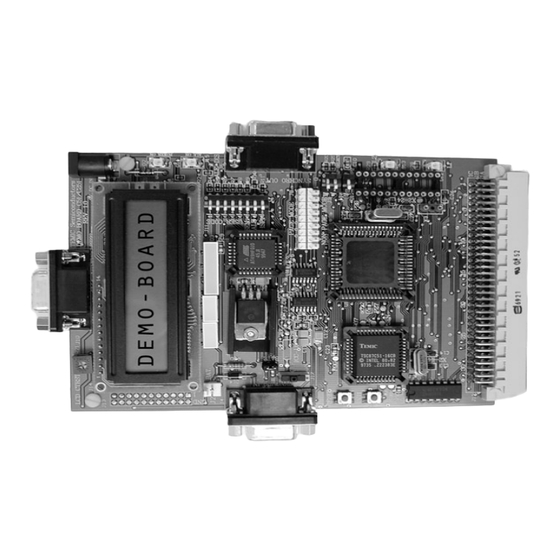
J8 Connector – Configure hardware in Page Mode or Non Page Mode. – for C251 microcontrollers. For C51 products, the configuration must be set to Non Page Mode. n Synchro IN – Used to connect several C51/C251 Demo Boards together, provides global reset / interrupt for all connected C51/C251 Demo Boards. -
Page 10: J11 Switches
Set to run demos Clear to program T89C51RD2 on-chip Flash memory User Code UC4:0 Free of use as data input for demos. (Set=1, Clear=0) RS232 Synchro OUT Page Mode Non Page Mode DIL24 PLCC68 Extension connector C51 Microcontrollers Demo Board User Guide... - Page 11 PLCC44, a PLCC68 and a DIL24. Each socket has it own quartz crystal X1, X2 and X3. Only one Atmel microcontroller must be plugged-in at one time, in one of the three sockets. Crystal may be easily changed on each socket.
-
Page 13: Operation Mode
PSEN ISP1 The C51/C251 Demo Board must be connected to a PC com port via the RS232 cable connected to the RS232 connector of C51/C251 Demo Board. After downloading, you can run code by switching PSEN on J11 to 1 and pressing the RESET push button. -
Page 14: Isp External Flash Memory Mode
External Flash memory might be programmed using Windows hyper terminal or any ter- minal able to send HEX files in text mode. The C51/C251 Demo Board must be connected to the PC com port with the cable con- nected to the RS232 connector J10. - Page 15 Figure 3-3. Com Port Configuration Figure 3-4. Terminal Window on Running ISP Turn on the C51/C251 Demo Board and then follow the instructions on the terminal screen and LCD display. After erasing Flash, the program asks for the memory zone, and then asks to send the HEX file in text mode (see Figure 3-4, Figure 3-5 &...
- Page 16 Operation Mode 3-13 4119C–8051–3/03 Figure 3-5. Send HEX File in Text Mode Figure 3-6. Use *.* in the Selection Zone to See HEX files in the Directory C51 Microcontrollers Demo Board User Guide...
-
Page 17: Demo Mode
(LCD or RS232). PSEN ISP1 MAP SELECT In C51 mode (Non Page Mode) switch J8 must be as shown in Figure 3-8. Used to select demo program Used to select display Used to select memory zone... -
Page 18: C251 Mode
In C251 mode, the microcontroller can be used in Page Mode or Non Page Mode. For Non Page Mode switch J8 must be in the same configuration as in C51 mode. For Page Mode switch J8 must be as shown in Figure 3-9. -
Page 19: Bill Of Material
POTENTIOMETER RESISTOR RESISTOR LM7805C LM2936Z5 U3-U4-U7-U8 74ACT573 TSC80C31 AT49HF010-45JC ICL232CBE HEF4555P TSC80C51 TSC80C51 74ACT14 74ACT00 Quartz_11.05920 Quartz_22,1184 C51 Microcontrollers Demo Board User Guide 4,7uF CMS_TAJ_Package_B 100nF Package_0805 3,3uF TAJ_CMS_Package_B 10uF TAJ_CMS_Package_B 22pF Serie_680 10uF CMS_TAJ_Package_B 1N4001 Package_DO204AL CMS_STANDART GREEN LED in_line_2.54mm step... -
Page 21: Schematics
Section 5 Schematics C51 Demo Board User Guide 5-18 Rev. 4119C–8051–3/03... - Page 22 Schematics 5-19 C51 Demo Board User Guide 4119C–8051–3/03...
- Page 23 Schematics C51 Demo Board User Guide 5-20 4119C–8051–3/03...
- Page 24 Schematics 5-21 C51 Demo Board User Guide 4119C–8051–3/03...
- Page 25 Schematics C51 Demo Board User Guide 5-22 4119C–8051–3/03...
- Page 26 Schematics 5-23 C51 Demo Board User Guide 4119C–8051–3/03...
- Page 27 No licenses to patents or other intellectual property of Atmel are granted by the Company in connection with the sale of Atmel products, expressly or by implication. Atmel’s products are not authorized for use as critical components in life support devices or systems.
Need help?
Do you have a question about the C51 and is the answer not in the manual?
Questions and answers