Table of Contents
Advertisement
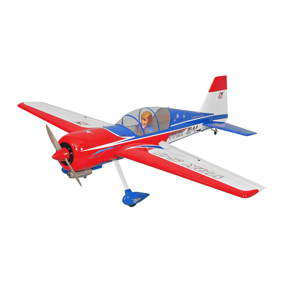
YAK54 MK2
GP/EP size.120/20cc SCALE 1:4 ¾ ARF
SPECIFICATION
- Wingspan: 1684mm (66.3 in)
- Length: 1605mm (63.1 in)
- Flying weight: 4700-5200 gr
- Wing area: 54.7 dm2
- Wing loading: 87g/dm2
- Wing type: Naca airfoils
- Covering type: Genuine ORACOVER®
- Gear type: Aluminum Hi-grade for main
gear and spring wire for tail gear (included)
- Spinner size: Plastic 70mm (included)
- Radio: 4 channel minimum (not included)
- Servo: 6 standard hitorque servo: 2 aileron;
2 elevator; 1 rudder; 1 throttle (not included)
- Recommended receiver battery:
4.8-6V / 1200-2000mAh NiMH (not included)
- Servo mount: 21mm x 42 mm
- Propeller: suit with your engine
Instruction Manual
- Engine: .120 / 2-stroke or .120/4-stroke glow
engine or 20cc gas engine (not included)
- Motor: brushless outrunner 2000-2400 W,
450 KV (not included)
- Gravity CG: 137 mm (5.3in) Back from the
leading edge of the wing, at the fuselage
- Control throw Ailerons: Low: 11mm up/down,
10% expo; High: 13mm up/down, 10% expo
- Control throw Elevators: Low: 11mm up/down,
12% expo; High: 13mm up/down, 12% expo
- Control throw Rudder: Low: 35mm right/left,
15% expo; High: 60mm right/left, 15% expo
- Experience level: Intermediate
- Plane type: Scale Aerobatic
RECOMMENDED MOTOR AND BATTERY SET UP
- Motor: RIMFIRE .120 (not included)
- Lipo cell: 6-12 cells / 4000 – 5500mAh
(not included)
- Esc: 80-100A (not included)
GP
EP
version
version
Advertisement
Table of Contents

Related Manuals for Phoenix Model YAK54 MK2


Summary of Contents for Phoenix Model YAK54 MK2
- Page 1 Instruction Manual version version YAK54 MK2 GP/EP size.120/20cc SCALE 1:4 ¾ ARF SPECIFICATION - Engine: .120 / 2-stroke or .120/4-stroke glow - Wingspan: 1684mm (66.3 in) engine or 20cc gas engine (not included) - Length: 1605mm (63.1 in) - Motor: brushless outrunner 2000-2400 W,...
-
Page 2: Tools And Supplies Needed
Please trial fit all the parts. Make sure you have the correct parts and that they fit and are aligned properly before gluing! This will assure proper assembly. The YAK54 MK2 GP/EP size.120/20cc SCALE 1:4 ¾ TEMPORARY PIN ARF is hand made from natural materials, every... -
Page 3: Installing The Ailerons Servos
YAK54 MK2 Instruction Manual Make certain the hinges are adequately secured with glue. If they come loose in flight accidents may result. Secure nylon hinges with instant glue, being careful not to glue the wing and airleron together. Apply instant glue (CA glue, super glue). -
Page 4: Installing The Aileron Linkages
YAK54 MK2 Instruction Manual INSTALLING THE AILERON LINKAGES 4. Center the aileron and hold it in place using a couple of pieces of masking tape. Adjust the 1. Install the control horn into the aileron. linkage until the aileron and the servo arm are both centered and then tighten the nut against. - Page 5 YAK54 MK2 Instruction Manual Neutral Aileron Aileron < Bottom view > Aluminum ball Silicone tube Apply threadlocker (screw cement). SECURE The Wing To The Fuselage Attach the wings to the fuselage and secure the 6x45mm Plastic Screw wing panels using 4 plastic screw.
-
Page 6: Installing The Main Landing Gear
YAK54 MK2 Instruction Manual INSTALLING THE MAIN LANDING GEAR 4 x 20mm Cap Screw 4mm Washer Collar 4mm Spring Washer 5mm Washer < Main Gear (R) > < Main Gear (L) > Collar Washer Collar Wheel Pant Main gear Collar... -
Page 7: Horizontal Stabilizer Installation
YAK54 MK2 Instruction Manual 4x20mm HORIZONTAL STABILIZER INSTALLATION When you are sure that everything is aligned correctly, mix up a generous amount of 30 minute epoxy. Apply a thin layer to the bottom and to the 1. Using a modeling knife, cut away the covering top of the stabilizer mounting area and to the from the fuselage for the stabilizer and remove it. -
Page 8: Vertical Stabilizer Installation
YAK54 MK2 Instruction Manual Warning! Make certain plane is aligned accurately per the diagram. A mis-aligned plane can fly erraticaliy and cause accidents. Apply epoxy glue Cut off shaded portion Secure nylon hinges with instant glue, being careful tail wing and elevator. -
Page 9: Installing The Rudder Linkages
YAK54 MK2 Instruction Manual INSTALLING THE RUDDER LINKAGES Slide a crimp onto the cable, then pass the cable through the threaded cable end. Pass The rudder is controlled by two metal cables. the cable back into the crimp and use crimping Install the rudder linkages and cables as below. -
Page 10: Installing The Elevator Servo
YAK54 MK2 Instruction Manual Rudder servo Cable rod Cable rod INSTALLING THE ELEVATOR SERVO INSTALLING THE ELEVATOR LINKAGES 1. Remove the covering from both size of the . Repeat these step as installing the aileron fuselage. linkages. 2. Install two servo to the fuselage as shown. - Page 11 YAK54 MK2 Instruction Manual Elevator rod Aluminum ball 3x12mm Apply threadlocker (screw cement). Pay close attention here Cut off shaded portion Must be purchased separately!
- Page 12 YAK54 MK2 Instruction Manual Must be purchased separately! Silicone Top Hatch Open and close Silicone INSTALLING THE Tail wheel 3x12mm 3 x 12mm TP Screw 3 x 15mm Cap Screw 3mm Spring Washer Spring Cut off shaded portion...
-
Page 13: Installing The Engine Mount
YAK54 MK2 Instruction Manual 3x15mm Spring INSTALLING THE ENGINE MOUNT 4 x 30mm Screw 4mm Washer 4mm Spring Washer 4x30mm Engine Mount 4x30mm Apply threadlocker (screw cement). -
Page 14: Installing The Fuel Tank
YAK54 MK2 Instruction Manual 7. Using a modeling knife, cut 3 lengths of fuel line INSTALLING THE Fuel Tank 150mm long. Connect 2 lines to the 2 vent tubes and 1 line to the fuel pickup tube in the 1. The stopper has been pre-assembled at the stopper. -
Page 15: Installing The Engine
YAK54 MK2 Instruction Manual Engine Mount Temporarily install the engine and make a hole for the throttle rod by aligning with the position of the throttle lever. PP Pipe Throttle rod INSTALLING THE ENGINE Locate the long piece of wire used for the throttle pushrod. -
Page 16: Installing The Throttle
YAK54 MK2 Instruction Manual OS 120 AX DLE 20 INSTALLING THE THROTTLE 3. Slide the adjustable metal connector / servo arm assembly over the plain end of the pushrod wire. 1. Install one adjustable metal connector through Position the throttle stick and the throttle trim at their lowest positions. -
Page 17: Mounting The Cowl
YAK54 MK2 Instruction Manual Adjust the throttle input (transmitter throttle stick), throttle trim movement and the carburattor opening to the suitable position and screw in the 4x4mm set screw. Throttle Servo MOUNTING THE COWL 4. While holding the cowl firmly in position, drill four 1,6mm pilot holes through both the cowl 1. -
Page 18: Installing The Spinner
YAK54 MK2 Instruction Manual 3x10mm INSTALLING THE SPINNER Install the spinner back-plate, propeller and spinner cone. The spinner cone is held in place using two screws. The propeller should not touch any part of the spinner cone. If it dose, use a sharp modeling knife and carefully trim away the spinner cone where the propeller comes in contact with it. -
Page 19: Installing The Receiver And Battery
YAK54 MK2 Instruction Manual INSTALLING THE RECEIVER AND BATTERY INSTALLING THE SWITCH 1. The switch should be mounted on the fuselage 1. Plug the servo leads and the switch lead into the side, opposite the muffler, close enough to the receiver. - Page 20 YAK54 MK2 Instruction Manual Battery Cord Velcro 4x70mm 4x70mm Battery White glue Must be purchased separately! When rotating clock wise, charge the connection of 2 wires. < Check the motor rotation >...
-
Page 21: Lateral Balance
YAK54 MK2 Instruction Manual BALANCING 3. Turn the airplane upside down. Place your fingers 1. It is critical that your airplane be balanced correctly. on the masking tape and carefully lift the plane. Improper balance will cause your plane to lose 4. -
Page 22: Flight Preparation Pre Flight Check
YAK54 MK2 Instruction Manual FLIGHT PREPARATION PRE FLIGHT CHECK 11mm 11mm 1. Completely charge your transmitter and receiver batteries before your first day of flying. Aileron Control 2. Check every bolt and every glue joint in your plane to ensure that everything is tight and well bonded. - Page 23 YAK54 MK2 Instruction Manual Main Gear Dimensional Detail 17.0 24.0 205.7 270.1 13.0 24.0 17.0 TAIL Gear Dimensional Detail 137.7 25.0 16.0 25.0...
-
Page 24: Exploded View
EXPLODED VIEW 3x20mm 3x20mm 3x25mm 3x25mm 2x10mm 4x4mm 3x12mm 3x15mm 4x20mm 3x25mm 4x70mm 3x10mm(TP) 4x30mm 4x30mm 4x30mm 3x12mm...
Need help?
Do you have a question about the YAK54 MK2 and is the answer not in the manual?
Questions and answers