
Subscribe to Our Youtube Channel
Related Manuals for Phoenix Model yak 55


Summary of Contents for Phoenix Model yak 55
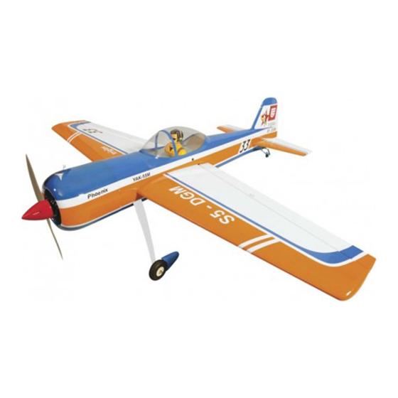
- Page 1 I n s t r u c t i o n M a n u a l Wingspan : 1842mm (72.52 inches) Length : 1759mm (69.25 inches) Weight : 5000g - 5500g Radio : 6 channel with 5 high torque servo + 1 standard servo Engine : Gas 25cc - 35cc...
-
Page 2: Kit Contents
Instruction Manual YAK 55 KIT CONTENTS: We have organized the parts as they come out of the box for better identification during assembly. We recommend that you regroup the parts in the same manner. This will ensure you have all of parts required before you begin assembly. -
Page 3: Tools And Supplies Needed
2. Turn the wing panel right side up. Using a 3. The YAK 55 size 25cc-35cc will perform 3-D modeling knife, remove the covering from over aerobatics easily if you use the largest the precut servo box. -
Page 4: Installing The Control Horns
Instruction Manual YAK 55 ↑ To the cowl Collar 6. Repeat step # 1 - # 5 to install the second aileron servo in the opposite wing half. 4. Tie the string from inside the wing to the end of the servo wire. -
Page 5: Installing The Aileron Linkages
Instruction Manual YAK 55 2. Install the link ball to the control horn. M3 nut 3. Repeat step # 1 - # 2 to install the second control horn on the aileron. ↑ To the cowl 4. Repeat step # 1 - # 3 to install the control horn for the second aileron. -
Page 6: Installing The Elevator Servo
Instruction Manual YAK 55 INSTALLING THE WING TO THE FUSELAGE Attach the wings to the joiner tube and using the nylon thumbscrews to secure the wing panels to the fuselage. Plastic screw 3. Remove the covering from the elevator to install the control horn. -
Page 7: Installing The Elevator Linkages
Instruction Manual YAK 55 INSTALLING THE HORIZONTAL STABILIZER INSTALLING THE ELEVATOR LINKAGES The elevator linkages are assembled as shown below 1. Remove the covering from the fuselage. Remove the covering 22mm 22mm 40mm . Repeat these step as installing the aileron linkages. -
Page 8: Installing The Vertical Stabilizer
Instruction Manual YAK 55 INSTALLING THE VERTICAL STABILIZER INSTALLING THE RUDDER LINKAGES The rudder is controlled by two metal cables. 1. Remove the covering from the bottom of the Install the rudder linkages and cables as below. rudder. 1. Use a hobby knife to remove the covering from the openings for the rudder control cables. -
Page 9: Installing The Tail Wheel
Instruction Manual YAK 55 Crimp Aluminum ball Crimp Cable M3 Clevis Plastic ball link Cable end Metal connector INSTALLING THE TAIL WHEEL 5. Thread the metal connector to the link ball. 1. The tail wheel set. 2. Remove the covering. -
Page 10: Installing The Wheel Pants
Instruction Manual YAK 55 INSTALLING THE WHEEL PANTS 4. Secure the tail brace to the fuselage. 1. Locate the wheel pants from the hardware bag. Mark the locations of the mounting axles onto the wheel pants. The locations of the two... -
Page 11: Installing The Stopper Assembly
Instruction Manual YAK 55 5. Test fit the stopper assembly into the tank. It may be necessary to remove some of the 165mm flashing around the tank opening using a modeling knife. If flashing is present, make sure none of it falls into the tank. -
Page 12: Mounting The Cowl
Instruction Manual YAK 55 C.A Glue Throttle MOUNTING THE COWL 1. Measure and mark the locations to be cut out for engine head clearance, needle valve, muffler. Remove the cowl and make these cut outs using a rotary tool with a cutting disc and a rotary sanding drum attachment. - Page 13 Instruction Manual YAK 55 Switch Engine switch 3. Secure the wing joiner using a 4mm x 35mm open and close the canopy wood screw. Screw INSTALLING and secure the wing BALANCING 1. Find the hole on the top of the wing by taking 1.
-
Page 14: Lateral Balance
35mm 130mm Rudder Control 3-D PERFORMANCE SETTINGS The YAK 55 will perform 3-D aerobatics easily if you use the largest engines recommended within the engine range. If you setup your airplane to do 3D maneuvers, you will need to LATERAL BALANCE be throttle conscious;... - Page 15 I/C FLIGHT WARNINGS Always operate in open areas, away Keep all onlookers (especially small from factories, hospitals, schools, THE PROPELLER IS DANGEROUS children and animals) well back from buildings and houses etc. NEVER fly Keep fingers, clothing (ties, shirt the area of operation. This is a flying your aircraft close to people or built sleeves, scarves) or any other loose aircraft, which will cause serious...
- Page 16 I/C FLIGHT GUIDELINES Operate the control sticks on the When ready to fly, first extend the transmitter and check that the control transmitter aerial. surfaces move freely and in the ALWAYS land the model INTO the CORRECT directions. wind, this ensures that the model lands at the slowest possible speed.
Need help?
Do you have a question about the yak 55 and is the answer not in the manual?
Questions and answers