Inogen One G3 User Manual
Hide thumbs
Also See for Inogen One G3:
- User manual ,
- Equipment manual (20 pages) ,
- Technical manual (20 pages)
Table of Contents
Advertisement
Quick Links
Advertisement
Table of Contents

Related Manuals for Inogen Inogen One G3


Summary of Contents for Inogen Inogen One G3
-
Page 1: User Manual
user manual ®... - Page 3 Chapter 1 Intended Use, Contraindications and General Precautions Chapter 2 Description of the Inogen One® G3 Oxygen Concentrator Important Parts of the Inogen One® G3 Oxygen Concentrator User Interfaces Input / Output Connections Power Supply Options Inogen One® G3 Accessories...
-
Page 5: Intended Use
One® G3 may be used in home, institution, vehicle, on an airplane and various mobile environments. The expected life for the Inogen One® G3 Oxygen System is 5 years, with the exception of the sieve beds (metal columns) which have an expected life of 1 year and the batteries, which have an expected life of 500 full charge/discharge cycles. - Page 6 Do NOT ALLOW SMOKING OR OPEN FLAMES within 10 feet of this device while in use. WARNING Do not submerse the Inogen One® G3 or any of the accessories in liquid. Do not expose to water or precipitation. Do not operate in exposed rain.
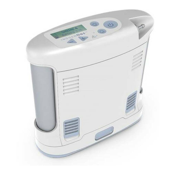
- Page 7 Important Parts of the Inogen One® G3 Oxygen Concentrator Display Back- Display Breath On/Off light Button Detection Light Button Flow Control Alert/Alarm Audible Alarm Light Button Description of the Inogen One® G3 Oxygen Concentrator Chapter 2 Description of the Inogen One® G3 Oxygen Concentrator Chapter 2...
- Page 8 Press once to turn “ON”; Press and hold for one second to turn “OFF”. Audible Alarm Button Pressing this button will toggle the Inogen One® G3’s breath detection audible alert on and off. Breath Detection Alert Mode. The Inogen One® G3 will alert with audible and visual signals for “no breath detected”...
- Page 9 The filters must be in place at the intake end of the concentrator during operation to keep input air clean. Cannula Nozzle Fitting The nasal cannula connects to this nozzle for Inogen One® G3 output of oxygenated air. DC Power In Connection for external power from the AC power supply or DC power cable.
- Page 10 See information in the “Battery Care and Maintenance” section. Power Supply Overview The Inogen One® G3 AC power supply (BA-301) is used to power the Inogen One® G3 concentrator from an AC power source. Description The Inogen One® G3 AC power supply is specifically designed for use with the Inogen One®...
- Page 11 Doing so may lead to damaged cords and a failure to provide power to the concentrator. To avoid danger of choking or strangulation hazard, keep cords and tubing away from children and pets. Description of the Inogen One® G3 Oxygen Concentrator Chapter 2...
- Page 12 Increasing the cannula length may reduce the perceived noise during oxygen bolus delivery. NOTE When using a cannula 25ft. in length with the Inogen One® G3, an increase in flow setting may be required. Carry Bag (CA-300) The carry bag provides protection while carrying the Inogen One® G3 with a handle and adjustable shoulder strap.
- Page 13 2. Plug the External Battery Charger AC power supply into the battery charger. 3. Slide your charger onto the Inogen One G3 Battery by clicking and locking into the charger. 4. When the battery is in the correct position, a solid red light will indicate that the battery is charging.
-
Page 15: Operating Instructions
Locate the Inogen One® G3 in such a way that any auditory alarms may be heard. Exhaust WARNING Avoid use of the Inogen One® G3 in presence of pollutants, smoke or fumes. Do not use the Inogen One® G3 in presence of flammable anesthetics, cleaning agents or other chemical vapors. - Page 16 CAUTION The Inogen One® G3 battery acts as a secondary power supply in the event of a planned or unexpected loss of the AC or DC external power supply. When operating the Inogen One® G3 from an AC or DC external power supply, a properly inserted Inogen One®...
- Page 17 7. Set the Inogen One® G3 Concentrator to the flow rate prescribed by your physician or clinician. Use the + or – setting buttons to adjust the Inogen One® G3 to the desired setting. The current setting can be viewed on the display.
- Page 18 CAUTION The Inogen One® G3 is designed to provide a flow of high purity oxygen. An advisory alarm, “Oxygen Low”, will inform you if oxygen concentration drops. If alarm persists, contact your equipment provider.
- Page 19 Traveling with your Inogen One® G3 System The Inogen One® G3 System makes travel by boat, car or train more convenient for oxygen users than ever before. Now you get the same quality performance and convenience while on the go that you’re used to receiving from your Inogen One®...
- Page 20 Traveling By Air The FAA allows the Inogen One® G3 onboard all U.S. aircraft, here are a few points to make air travel easy. Planning Your Flight When flying with the Inogen One®...
- Page 21 • Some airlines may equip their aircraft with onboard electrical power. You may have an opportunity to request a seat with a power port which can be used to power your Inogen One® G3. However, availability varies by airline, type of aircraft and class of service. You should check with your airlines for availability and always plan on having sufficient battery power for no less than 150% of the expected duration of the flight.
- Page 22 Your Inogen One® G3 will fit upright under most airline seats. However, if it doesn’t fit you may turn it on its side with vents facing up. • It is not necessary to turn off your Inogen One® G3 during taxi, takeoff and landing if your physician’s written statement requires you receive oxygen during these periods.
- Page 23 When battery life is low, do one of the following: • Plug the Inogen One® G3 into an AC or DC power source using the AC power supply or DC cable. • Replace the battery with a charged battery after turning off the Inogen One® G3 (by pressing the ON/OFF button).
- Page 24 Effect of Temperature on Battery Performance The Inogen One® G3 single battery powers the Inogen One® G3 Concentrator up to 4.5 hours under most environmental conditions. To extend the run-time of your battery, avoid running in temperatures less than 41˚F (5˚C) or higher than 95˚F (35˚C) for extended periods of time.
- Page 25 Power Display Icons The Inogen One® G3 display is divided into three areas. The upper left corner of the display shows the breath detection alert status. The lower left corner indicates power source and battery charge level. The right side of the display contains text information, such as flow setting, battery time remaining and error notifications.
- Page 26 Power Status Icons (continued) The icons below are examples of those shown when the Inogen One® G3 is operating from an external power supply and charging the battery. The lightning bolt indicates that an external power supply is connected. Icon Meaning Battery is charging with charge level between 60% and 70%.
- Page 27 The following information displays are not accompanied by any audible feedback or any visual change in the indicator lights. Message Display & Text Condition/Action/Explanation The Inogen logo is displayed at startup. Setting X Displayed during warm up. “X” represents the selected flow Please Wait setting (eg., Setting 2).
- Page 28 Notifications (continued) The Inogen One® G3 monitors various parameters during operation and utilizes an intelligent alarm system to indicate a malfunction of the concentrator. Mathematical algorithms and time delays are used to reduce the probability of false alarms while still ensuring proper notification of an alarm condition.
- Page 29 10-15 minutes. Then, re-insert the battery into the Inogen One® G3. If the problem still persists, contact your equipment provider. Concentrator is producing oxygen but cannot report Comm Error battery status.
- Page 30 Medium Priority Alerts The following medium priority alert messages are accompanied by a triple beep, repeated every 25 seconds, and a flashing red light. Message Display & Text Condition/Action/Explanation No Breath Detect Concentrator has not detected a breath for 60 seconds. Check Cannula Check that cannula is connected to concentrator, there are no kinks in tubing and cannula is positioned properly in...
- Page 31 High Priority Alerts CAUTION If you are not near the Inogen One® G3 you may not be able to hear or see the high priority alerts. Make sure the Inogen One® G3 is in a location where the alerts and alarms will be recognized if they occur.
- Page 32 High Priority Alerts (continued) Message Display & Text Condition/Action/Explanation System COLD This may result from the concentrator being stored in a cold environment (below 0ºC (32ºF)). Move to a warmer environment to allow the unit to warm up before starting it.
-
Page 33: Troubleshooting
Troubleshooting Solutions to some possible issues you may encounter are described in this section. Inogen One® G3 Oxygen Concentrator Problem Possible Cause Recommended Solution Any problem Refer to Chapter 4 Refer to Chapter 4 accompanied by information on concentrator display, indicator... - Page 34 Troubleshooting (continued) Problem Possible Cause Recommended Solution No oxygen Concentrator is not Press On/Off button to power powered on concentrator Cannula is not Check cannula and its connection connected properly to concentrator nozzle or is kinked or obstructed...
- Page 35 You may clean the outside case using a cloth dampened with a mild liquid detergent (such as Dawn ) and water. WARNING Do not submerse the Inogen One® G3 or its accessories in water or allow water to enter into the case; this may lead to electrical shock and/or damage.
- Page 36 The output filter may be replaced by the equipment provider or by the owner using the Output Filter Replacement Kit (RP-107). The Inogen One G3 Concentrator must be cleaned and disinfected as per the above instructions for each new patient. No special maintenance needs to be carried out by the patient.
- Page 37 Column change instructions are only to be used when maintenance is required and are not intended for practice purpose. 1. Turn off the Inogen One® G3 concentrator by pressing the power button to shut down the device. 2. Remove the Inogen One® G3 concentrator from the carry bag.
- Page 38 Inogen One® G3 Column Change Procedure (continued) Open and unlocked 6. Remove column by pressing the latch button with thumb or finger. 7. While holding the button open, slide the column (metal tube) out by gripping the exposed aluminum surface with other hand.
- Page 39 Inogen One® G3 Column Change Procedure (continued) 11. Insert column (metal tube) into the Inogen One® G3 concentrator. Do not leave the column exposed; it should be inserted into the Inogen One G3 as soon as the dust caps have been removed. Closed and locked 12.
- Page 40 Other Service and Maintenance WARNING Do not disassemble the Inogen One® G3 or any of the accessories or attempt any maintenance other than tasks described in this user manual; disassembly creates a hazard of electrical shock and will void your warranty. Do not remove the tamper evident label.
-
Page 41: Symbols Used
Symbols Used On Concentrator and Accessories Symbol Meaning A warning indicates that the personal safety of the patient may be WARNING involved. Disregarding a warning could result in significant injury. A caution indicates that a precaution or service procedure must be followed. - Page 42 Symbol Meaning Keep Dry Indoor or Dry Location Use Only, Do Not Get Wet Use No Oil or Grease ONLY Do Not Disassemble (contact your equipment provider for servicing by authorized personnel) Do Not Dispose of In Unsorted Municipal Waste ONLY Type BF Applied Part, Not Intended for Cardiac Application Class II Device...
- Page 43 Temperature: -13 to 158˚F (-25 to 70˚C) Intended for Shipping and Humidity: 0% to 95%, non-condensing Storage: Store in a dry environment Altitude: 0 to 10,000 ft (0 to 3048 meters) Transportation: Keep Dry, Handle With Care Inogen One® G3 System Specifications Chapter 8...
- Page 44 Inogen One® G3 Concentrator (continued) Tested by Independent Safety: IEC 60601-1 Laboratory: CAN/CSA C22.2 No. 60601-1 Electromagnetic Compatibility: IEC 60601-1-2 RTCA DO 160 Classifications Mode of Operation: Continuous Duty Type of Protection Against Electrical Class II Shock: Degree of Protection to Concentrator...
- Page 45 Guidance and Manufacturer’s Declaration - Electromagnetic Immunity: The Concentrator is intended for use in the electromagnetic environment specified below. The user of the Concentrator should make sure it is used in such an environment. Immunity Test IEC 60601 Compliance Electromagnetic Test Level Level Environment - Guidance...
- Page 46 NOTE At 80 MHz and 800 MHz, the higher frequency range applies. NOTE These guidelines may not apply in all situations. Electromagnetic propagation is affected by absorption and reflection from structures, objects, and people. NOTE is the a.c. main voltage prior to application of the test level. : Field strength from fixed transmitters, such as base stations for radio (cellular/cordless) telephones and land mobile radios, amateur radio, AM and FM radio broadcast and TV broadcast cannot be predicted theoretically with accuracy.
Need help?
Do you have a question about the Inogen One G3 and is the answer not in the manual?
Questions and answers
Why is my Inogen not holding a charge?
Why does message say OXYGEN LOW when portable is charged 87% charged?
Getting Low Oxygen error code