Table of Contents
Advertisement
OPERATING MANUAL
BEDIENUNGSANLEITUNG
MODE D'EMPLOI
MANUAL DE FUNCIONAMIENTO
MANUALE DI ISTRUZIONI
ΕΓΧΕΙΡΙ∆ΙΟ ΛΕΙΤΟΥΡΓΙΑΣ
MANUAL DE INSTRUÇÕES
РУКОВОДСТВО ПО ЭКСПЛУАТАЦИИ
HEAT & COOL MODEL
(REVERSE CYCLE)
ROOM AIR CONDITIONER
WALL MOUNTED TYPE
Indoor Unit
AWY14LSACW
AWY17LSACW
Outdoor Unit
AOY14LSAWC
AOY17LSAWC
KEEP THIS OPERATION MANUAL
FOR FUTURE REFERENCE
FUJITSU GENERAL LIMITED
P/N9312556014-01
2003.6.11, 5:03 PM
Advertisement
Table of Contents

Related Manuals for Fujitsu AWY14LSACW


Summary of Contents for Fujitsu AWY14LSACW
- Page 1 MANUAL DE INSTRUÇÕES РУКОВОДСТВО ПО ЭКСПЛУАТАЦИИ HEAT & COOL MODEL (REVERSE CYCLE) ROOM AIR CONDITIONER WALL MOUNTED TYPE Indoor Unit AWY14LSACW AWY17LSACW Outdoor Unit AOY14LSAWC AOY17LSAWC KEEP THIS OPERATION MANUAL FOR FUTURE REFERENCE FUJITSU GENERAL LIMITED P/N9312556014-01 2003.6.11, 5:03 PM...
- Page 2 EC Council Directive 89/336/EEC Place of Issue : F.R. Germany Title of Authority : General Manager Date of Issue : 14. FEBRUARY 2003 Declaration Reference : FUJITSU GENERAL (EURO) GmbH Werftstraße 20, D-40549 Düsseldorf, F. R. Germany Authorized by : Signature: JUNJI YANAGIMOTO...
- Page 3 Fig. 1 Fig. 2 Fig. 4 Fig. 3 Fig. 6 Fig. 5 Fig. 7 This figure shows the control display when all indicator lamps are on. It may differ from the actual display. 9312556014-Cover.pm6.5...
-
Page 4: Table Of Contents
CONTENTS SAFETY PRECAUTIONS ........En-1 UN AIR CLEANING/ANION OPERATION ..En-13 FEATURES AND FUNCTIONS ......En-2 COIL DRY OPERATION ........En-14 NAME OF PARTS ..........En-3 MANUAL AUTO OPERATION ......En-15 PREPARATION ..........En-4 TEMPERATURE MONITORING ...... En-16 OPERATION ............En-6 AUTOMATIC FILTER CLEANING TIMER OPERATION .......... -
Page 5: Features And Functions
FEATURES AND FUNCTIONS INVERTER SWING OPERATION At the start of operation, a large power is used to bring the The airflow-direction louvers move (swing) automatically. room quickly to the desired temperature. Afterwards, the In addition, up, down, left, and right airflow directions can unit automatically switches to a low power setting for eco- be selected using the remote control unit. -
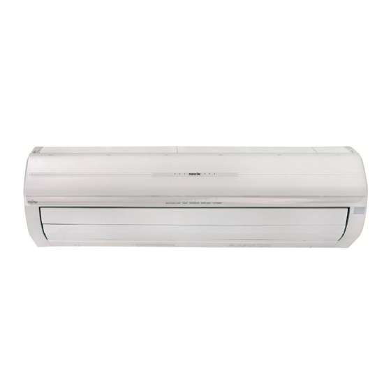
Page 6: Name Of Parts
NAME OF PARTS Fig. 1 Indoor Unit Fig. 5 Remote Control Unit 1 Intake Grilles O Signal Transmitter 2 Open Grille P Remote Control Unit Display 3 Indicator Q Transmit Indicator (Fig. 6) 4 Remote Control Signal Receiver (Fig. 2) R Clock/OFF TIMER Display 5 OPERATION Indicator Lamp S ON TIMER Display... -
Page 7: Preparation
PREPARATION About the Remote Control Unit operation and display (dedicated display function) G When a button is pressed on the Remote Control Unit, only indicators related to that operation appear on the Remote Control Unit display while unrelated indica- tors disappear (dedicated display function). This function allows easy confirma- tion of operation contents and is very convenient. - Page 8 CAUTION! Turn on the Power G Take care to prevent infants from accidentally swallowing batteries. Connect the Power Supply Plug (Fig. 1 J) to an electrical outlet; G When not using the Remote Control Unit in the case of a direct line connection, turn on the circuit breaker. for an extended period, remove the batteries to avoid possible leakage and damage to the unit.
-
Page 9: Operation
OPERATION To Select Mode Operation Press the START/STOP button (Fig. 5 `). The Indoor Unit’s OPERATION Indicator Lamp (red) (Fig. 2 5) will light. The air conditioner will start operating. Press the MASTER CONTROL button (Fig. 6 d) to se- lect the desired mode. - Page 10 To Stop Operation Press the START/STOP button. The OPERATION Indicator Lamp (red) (Fig. 2 5) will go out. About AUTO CHANGEOVER Operation G When AUTO CHANGEOVER operation first selected, the fan will oper- AUTO: ate at very low speed for about one minute, during which time the unit detects the room conditions and selects the proper operating mode.
-
Page 11: Timer Operation
TIMER OPERATION Before using the timer function,be sure that the Remote Control Unit is set to the correct current time (See page 5). To Use the OFF TIMER or ON TIMER To Cancel the Timer Open the Remote Control Unit lid to perform the timer function settings. Press the CANCEL button. -
Page 12: Sleep Timer Operation
SLEEP TIMER OPERATION Unlike other timer functions, the SLEEP timer is used to set the length of time until air conditioner operate is stopped. To Use the SLEEP timer To Cancel the Timer: While the air conditioner is operating or stopped, press the Press the CANCEL (TIMER) button. -
Page 13: Adjusting The Direction Of Air Circulation
ADJUSTING THE DIRECTION OF AIR CIRCULATION G Adjust the up, down, left, and right AIR directions with the AIR DIRECTION buttons on the Remote Control Unit. G Use the AIR DIRECTION buttons after the Indoor Unit has started operating and the airflow-direction louvers have stopped moving. -
Page 14: Swing Operation
SWING OPERATION Begin air conditioner operation before performing this procedure. To select SWING Operation Open the Remote Control Unit lid to perform swing operation settings. Press the SWING button (Fig. 5 m). The SWING Display (Fig. 6 T) will light. Each time the SWING button is pressed, the swing operation will change in the following order. -
Page 15: Economy Operation
ECONOMY OPERATION During Air Conditioner Operation Open the remote control unit lid, and then press the ECONOMY operation button. “ECO” appears on the Remote Control Unit display. G Economy operation begins. Press the ECONOMY Operation button again “ECO” disappears from the Remote Control Unit display. G Normal operation begins. - Page 16 G During heating mode The room temperature is 2°C above the thermostat setting. G During cooling mode The room temperature is 1°C below the thermostat setting or 30 minutes has passed since the HI-POWER operation began. G During fan mode 15 minutes has passed since the HI-POWER operation began.
-
Page 17: Coil Dry Operation
COIL DRY OPERATION G When the COIL DRY button on the Remote Control Unit is pressed, the inside of the Indoor Unit is dried, and then the UV (ultraviolet rays) lamp produces small amounts of ozone to suppress the growth of mold and various germs. G After the COIL DRY button is pressed, COIL DRY operation is performed for approximately 30 minutes and then automati- cally stops. -
Page 18: Manual Auto Operation
MANUAL AUTO OPERATION Use the MANUAL AUTO operation in the event the Remote Control Unit is lost or otherwise unavailable. REMOTE CONTROL UNIT UNAVAILABLE (MANUAL AUTO OPERATION) If the Remote Control Unit is lost or the batteries are dead, the air conditioner can be operated provisionally from the indoor unit. -
Page 19: Temperature Monitoring
TEMPERATURE MONITORING G The room temperature and the outdoor temperature can be displayed. This information is helpful in selecting the appro- priate operation mode and thermostat setting. G Use this function after the air conditioner is operating. To change the Temperature Monitoring During air conditioner operation, G Each time the MONITOR button is pressed, the display on the Indoor press the MONITOR button. -
Page 20: Automatic Filter Cleaning
AUTOMATIC FILTER CLEANING FUNCTION G This is a convenient function that automatically removes dust from the air filters after a set amount of time of air conditioner operation. G The automatic filter cleaning function can also be started using the remote control unit. Automatic Filter Cleaning CAUTION! Do not touch the air filters during the... - Page 21 G If the air filters are pulled or pushed during the automatic filter cleaning, the air filters will stop moving and the MAINTENANCE Indicator Lamp (green) will flash. If this occurs, follow procedures 1 and 4 in Dust box MAINTENANCE (see pages 19 and 21) to install the air filters.
- Page 22 PERFORMING MAINTENANCE G Frequent maintenance will extend the life of the air conditioner and improve the cooling and heating performance. G Before maintenance, stop air conditioner operation using the remote control and unplug the power supply cord from the electrical outlet. CAUTION! Before cleaning the air conditioner, be sure to When cleaning the air conditioner, do not...
- Page 23 2. Remove the dust collected in the dust boxes and clean the dust boxes. 1. Open the dust boxes. G When opening each dust box, make sure the front case <Rear case (dark blue)> is facing down and the rear case is facing up. If the Grab the tab on each brush holder on the rear case, open front case is facing up, a lot of dust will fall out of the the brush holders, and then dispose of the collected dust.
- Page 24 3. Assemble the dust boxes, and install the air filters. 1. Assemble each dust box. 2. Install the air filters in the dust boxes. 1 Place the front casing facing down and insert the pro- 1 Align the insertion directions written on each dust box jection on the rear case into the hole in the front case.
- Page 25 PERFORMING MAINTENANCE (CONTINUED) Air Filter Maintenance G Wash the air filters with water if small dust particles remain on the air filters even after automatic filter cleaning is per- formed. G It is recommended to perform dust box maintenance when the air filter maintenance is performed. 1.
- Page 26 PERFORMING MAINTENANCE (CONTINUED) Intake Grille Maintenance G Perform dust box maintenance at the same time. CAUTION! Intake grilles Be sure to install the intake grilles securely. G If the intake grilles are not installed securely, they may fall and cause personal injury. 1.
- Page 27 ANION GENERATOR MAINTENANCE G Perform anion generator maintenance every 6 months. G If anion generator produces hissing, buzzing, or crack- ling sounds, perform maintenance even if 6 months has not passed since the last maintenance. Anion generator (located deep in the air outlet) G Stop the air conditioner using the remote control unit.
-
Page 28: Function
TROUBLESHOOTING In the event of a malfunction (burning smell, etc.), immediately stop operation, disconnect the WARNING! Power Supply Plug, and consult authorized service personnel. Merely turning off the unit’s power switch will not completely disconnect the unit from the power source. -
Page 29: Troubleshooting
TROUBLESHOOTING Symptom Items to check See Page G Is the Power Supply Plug disconnected its outlet? CHECK ONCE Doesn’t operate at all: MORE G Has there been a power failure? — G Has a fuse blown out, or a circuit breaker been tripped? G Is the timer operating? 8 - 9 G Is the Air Filter dirty? - Page 30 OPERATING TIPS Temperature and Humidity Range Cooling Mode Dry Mode Heating Mode Outdoor temperature About 21-43 °C About 21-43 °C About –5-24 °C Indoor temperature About 18-32 °C About 18-32 °C About 27 °C or less G If the air conditioner is used under higher temperature conditioner than those listed, the built-in protection circuit may operate to prevent internal circuit damage.
- Page 31 INDOOR UNIT UNIDAD INTERIOR MODEL INNENGERÄT APPARECCHIO INTERNO AWY14LSACW MODELL UNITÉ INTÉRIEURE ΕΣΩΤΕΡΙΚΗ ΜΟΝΑ∆Α MODÈLE MODELO OUTDOOR UNIT UNIDAD EXTERIOR MODELLO AUSSENGERÄT APPARECCHIO ESTERNO AOY14LSAWC ΜΟΝΤΕΛΟ UNITÉ EXTÉRIEURE ΕΞΩΤΕΡΙΚΗ ΜΟΝΑ∆Α ESPECIFICACIONES ALIMENTACIÓN ..................230 V~50 Hz PRESIÓN MÁX. SUCCIÓN ....................1.160 kPa REFRIGERACIÓN...
- Page 32 TIPO MODELO DE AQUECIMENTO E ARREFECIMENTO (CICLO REVERSO) INVERSOR ТИП МОДЕЛЬ С РЕЖИМОМ ОХЛАЖДЕНИЯ И ОБОГРЕВА (ОБРАТНЫЙ ЦИКЛ) ИНВЕРТОР UNIDADE INTERNA AWY14LSACW MODELO ВНУТРЕННИЙ ПРИБОР UNIDADE EXTERNA МОДЕЛЬ AOY14LSAWC НAРУЖНЫЙ ПРИБОР FICHA TECNICA ALIMENTAÇÃO ..................230 V~50 Hz PRESSÃO MÁXIMA ASPIRAÇÃO .....................
Need help?
Do you have a question about the AWY14LSACW and is the answer not in the manual?
Questions and answers