
Subscribe to Our Youtube Channel
Related Manuals for Microchip Technology KSZ8061MNX


Summary of Contents for Microchip Technology KSZ8061MNX
-
Page 1: Evaluation Board
KSZ8061MNX Evaluation Board User’s Guide 2016 Microchip Technology Inc. DS50002449A... - Page 2 ViewSpan, WiperLock, Wireless DNA, and ZENA are trademarks of Microchip Technology Incorporated in the U.S.A. and other countries. SQTP is a service mark of Microchip Technology Incorporated in the U.S.A. Silicon Storage Technology is a registered trademark of Microchip Technology Inc. in other countries.
- Page 3 Object of Declaration: KSZ8061MNX Evaluation Board 2016 Microchip Technology Inc. DS50002449A-page 3...
- Page 4 NOTES: 2016 Microchip Technology Inc. DS50002449A-page 4...
-
Page 5: Table Of Contents
2.9 10-Pin Header (J7) ..................20 2.10 Status Indicator LEDs ................. 20 2.11 Reset Buttons ..................... 21 2.12 Jumpers ...................... 21 2.13 KSZ8061MNX Strapping Options ............... 22 2.14 MDIO/MDC Software Utility and FTDI Cable ..........22 Appendix A. Schematic and Layouts A.1 Introduction ....................25 Appendix B. - Page 6 KSZ8061MNX Evaluation Board User’s Guide NOTES: 2016 Microchip Technology Inc. DS50002449A-page 6...
-
Page 7: Preface
• The Microchip Web Site • Customer Support • Revision History DOCUMENT LAYOUT This document describes how to use the KSZ8061MNX Evaluation Board as a devel- opment tool. The document is organized as follows: • Chapter 1. “Product Overview” – This chapter includes important information about the KSZ8061MNX Evaluation Board. -
Page 8: Conventions Used In This Guide
KSZ8061MNX Evaluation Board User’s Guide CONVENTIONS USED IN THIS GUIDE This manual uses the following documentation conventions: DOCUMENTATION CONVENTIONS Description Represents Examples Arial font: ® Italic characters Referenced books MPLAB IDE User’s Guide Emphasized text ...is the only compiler... Initial caps... -
Page 9: Recommended Reading
Preface RECOMMENDED READING This user's guide describes how to use KSZ8061MNX Evaluation Board. Other useful documents are listed below. The following Microchip documents are available and recommended as supplemental reference resources: • KSZ8061MNX/KSZ8061MNG Data Sheet This data sheet provides detailed information regarding the KSZ8061MNX device. - Page 10 KSZ8061MNX Evaluation Board User’s Guide NOTES: 2016 Microchip Technology Inc. DS50002449A-page 10...
-
Page 11: Chapter 1. Product Overview
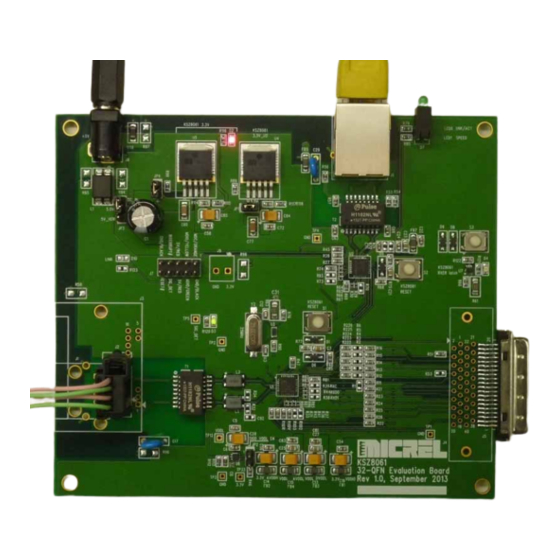
The KSZ8061MNX Evaluation Board is designed to enable functional and performance testing of the KSZ8061MNX PHY. In addition to the KSZ8061 PHY, there is a second PHY–a KSZ8081. The KSZ8081 is a standard 10/100 Ethernet PHY. It is used here to provide a second line interface for simple full-duplex traffic through the KSZ8061. - Page 12 KSZ8061MNX Evaluation Board User’s Guide FIGURE 1-2: KSZ8061MNX EVALUATION BOARD COMPONENTS 2016 Microchip Technology Inc. DS50002449A-page 12...
-
Page 13: Chapter 2. Configuration
3. MII Connector The MII edge connector (J5) allows the KSZ8061MNX Evaluation Board to be connected to the MAC port of a Microchip switch evaluation board, or to any other device with an Ethernet MAC interface. Full duplex traffic can pass between the MII connector and the KSZ8061 line interface (J1, J2 or J3). - Page 14 KSZ8061MNX Evaluation Board User’s Guide FIGURE 2-1: KSZ8061MNX EVALUATION BOARD IN TWO-PHY MII BACK-TO-BACK MODE 2016 Microchip Technology Inc. DS50002449A-page 14...
- Page 15 Configuration FIGURE 2-2: KSZ8061MNX EVALUATION BOARD IN MII LOOPBACK MODE WITH USB-TO-MDIO/MDC CABLE ON J7 FIGURE 2-3: KSZ8061MNX EVALUATION BOARD IN MII CONNECTOR MODE, WITH ETHERNET SWITCH 2016 Microchip Technology Inc. DS50002449A-page 15...
-
Page 16: Configuration Instructions
KSZ8061MNX Evaluation Board User’s Guide CONFIGURATION INSTRUCTIONS These instructions detail how to change between configurations. Figure 2-4 Figure 2-5 show the location of the components referenced in the instructions. 1. Two-PHY MII Back-to-Back Configuration. This is the default configuration, so these steps are only necessary if switching the board back from another configuration. - Page 17 Configuration FIGURE 2-4: TOP SIDE COMPONENTS FOR CONFIGURTION CHANGES FIGURE 2-5: BOTTOM SIDE COMPONENTS FOR CONFIGURATION CHANGES 2016 Microchip Technology Inc. DS50002449A-page 17...
-
Page 18: Power
KSZ8061MNX Evaluation Board User’s Guide POWER The evaluation board requires a DC supply at barrel connector J8. A jumper must be installed on pins 2-3 of JP3. The voltage requirement is 4.5V to 14V. The current requirement is 200 mA. -
Page 19: Line Interface Connector Options
3. J3: Sumitomo TS series 16-pin, part number 6098-6793 (Mating receptacle is 6098-4008) Table 2-1 lists the signal connections for each connector. Also refer to the schematic or PCB layout file since connector pin numbering may not be standardized. 2016 Microchip Technology Inc. DS50002449A-page 19... -
Page 20: Mii Connector
KSZ8061MNX Evaluation Board User’s Guide TABLE 2-1: KSZ8061 CONNECTOR PIN ASSIGNMENTS Connector Pin Assignment KSZ8061 Signal Sumitomo RJ-45 TE 1379165-1 6098-6793 MII CONNECTOR The MII edge connector J5 provides external access to the KSZ8061 MII bus and the MII management interface (MDIO/MDC). This connector is typically used to connect the KSZ8061 PHY to the MAC interface on a Microchip Ethernet switch evaluation board. -
Page 21: Status Indicator Leds
The board has three push buttons, which are all used for reset purposes: • S1: Chip reset for KSZ8061 (U1) • S2: Chip reset for KSZ8081 (U2) • S3: KSZ8061 RXER latch reset (U7, D4) 2016 Microchip Technology Inc. DS50002449A-page 21... -
Page 22: Jumpers
Resistors R36-R44 are used to select optional strapping configurations to the KSZ8061MNX. When a resistor is not installed, the internal resistor for each pin pulls it to its default level during reset. Installing a resistor pulls the pin to the opposite logic level. -
Page 23: Mdio/Mdc Software Utility And Ftdi Cable
ETHUTIL.EXE UTILITY - OPENING SCREEN AND ADDRESS COMMAND If the KSZ8081 is removed, disabled or if power is disconnected, then the utility will automatically configure itself for the KSZ8061 instead of the KSZ8081. This is shown Figure 2-11. 2016 Microchip Technology Inc. DS50002449A-page 23... - Page 24 KSZ8061MNX Evaluation Board User’s Guide FIGURE 2-11: ETHUTIL.EXE UTILITY WHEN KSZ8081 MDIO/MDC IS OFF Commands for ethutil.exe can be saved in ordinary text files and run using the “run” command. This is a simple form of scripting. It is suggested to have an “address 1"...
-
Page 25: Appendix A. Schematic And Layouts
Thermocouple IC Evaluation Board: • Figure A-1: “Board Schematic 1 of 4” • Figure A-2: “Board Schematic 2 of 4” • Figure A-3: “Board Schematic 3 of 4” • Figure A-4: “Board Schematic 4 of 4” 2016 Microchip Technology Inc. DS50002449A-page 25... - Page 26 RESET_IN KSZ8061 MII loopback Install Remove Remove MDIO MDIO_H10 Strapping Options (Refer to data sheet for descriptions) Labels for 5x2 Header: Configuration options for KSZ8061MNX VDDIO RX_ER Flip Flop RESET_IN MDC / ORANGE GND / BLACK PHYAD0 RXD3_U1 Opt/4.7K Opt/4.7K...
- Page 27 FIGURE A-2: BOARD SCHEMATIC 2 OF 4 Component placement for this schematic page will allow for flow thru routing of TX and RX These components are optional. They are suggested only for applications requiring maximum noise immunity. differential pairs on top PCB layer. TX+_U1 TX-_U1 TX+_U1...
- Page 28 FIGURE A-3: BOARD SCHEMATIC 3 OF 4 Notes: 1. KSZ8081 has a Paddle Ground on bottom side of chip. 3.3V_U2 3.3A_U2 3.3V_U2 Refer to datasheet for mechanical dimensions. Push Button LEDs Reset FBEAD FBEAD LED0 LINK/ACT BAV16W-7 SOD-123 BAV16W-7 SOD-123 10uF 10uF 3.3V_U2...
- Page 29 Closed: Second PHY (KSZ8081) is powered Open: Second PHY is unpowered TDK ZJYS81 TDK ZJYS81 EXT_GND When using terminal block (3.3V only), 3.3V Power for KSZ8061MNX 3.3V 3.3V VDDIO 1. Remove JP1 and JP4 to disable LDOs U4 and U5. 3.3V 2.
-
Page 30: Microchip Technology Inc. Ds50002449A
KSZ8061MNX Evaluation Board User’s Guide NOTES: 2016 Microchip Technology Inc. DS50002449A-page 30... -
Page 31: Appendix B. Bill Of Materials (Bom)
LED 0805 Lite-On LTST-C171GKT Lumex SML-LX0805SGC-TR DNI 1 LED - GREEN SMD LED 0805 Lite-On LTST-C171GKT Lumex SML-LX0805SGC-TR LED, green, stacked Dual LED (thru hole) Lumex SSF-LXH240GGD pair, right angle, thru Dialight 553-0122-300F hole 2016 Microchip Technology Inc. DS50002449A-page 31... - Page 32 0603 DNI 7 R36, R37, R38, Opt/4.7K 0603 R39, R44, R70, R40, R41, R42, 4.7K 0603 R46, R51, R68, R69, R74, R78, R89, R99 DNI 4 R43, R71, R72, Opt/1K 0603 6.49K 0603 2016 Microchip Technology Inc. DS50002449A-page 32...
- Page 33 74LVC1G175 single SC70 TI SN74LVC1G175DCK flip flop w/ async clear 25 MHz 5x3.2 mm, 2-ld TXC 7A-25.000MAAE NDK NX5032GA CTS 445C23L25M00000 TXC AA-25.000MAGE 25 MHz HC-49/SMD ECS ECS-250-18-5PX-F Abracon ABLS-25.000MHZ-B4-F-T TXC 9C-25.000MAAJ-T ILSI HC49USM-FB1F18-25.000 2016 Microchip Technology Inc. DS50002449A-page 33...
-
Page 34: Worldwide Sales And Service
Tel: 886-2-2508-8600 China - Xian Tel: 631-435-6000 Tel: 86-29-8833-7252 Fax: 886-2-2508-0102 San Jose, CA Fax: 86-29-8833-7256 Thailand - Bangkok Tel: 408-735-9110 Tel: 66-2-694-1351 Canada - Toronto Fax: 66-2-694-1350 Tel: 905-673-0699 Fax: 905-673-6509 07/14/15 2016 Microchip Technology Inc. DS50002449A-page 34...
Need help?
Do you have a question about the KSZ8061MNX and is the answer not in the manual?
Questions and answers