
Related Manuals for Microchip Technology dsPICDEM MCLV-2


Summary of Contents for Microchip Technology dsPICDEM MCLV-2
- Page 1 MCLV-2 Development Board User’s Guide 2012 Microchip Technology Inc. DS52080A...
- Page 2 Select Mode, Total Endurance, TSHARC, UniWinDriver, WiperLock and ZENA are trademarks of Microchip Technology Incorporated in the U.S.A. and other countries. SQTP is a service mark of Microchip Technology Incorporated in the U.S.A. All other trademarks mentioned herein are property of their respective companies.
- Page 3 2012 Microchip Technology Inc. DS52080A-page 3...
- Page 4 MCLV-2 Development Board User’s Guide NOTES: 2012 Microchip Technology Inc. DS52080A-page 4...
-
Page 5: Table Of Contents
BOARD USER’S GUIDE Table of Contents Preface ........................... 7 Chapter 1. Introduction 1.1 Overview of the dsPICDEM MCLV-2 Development Board ......13 1.2 Features Overview ..................14 Chapter 2. Hardware Overview 2.1 PIM Configuration ..................18 2.2 Board Connectors ..................20 2.3 Selecting a Power Supply for the Development Board ........ - Page 6 MCLV-2 Development Board User’s Guide NOTES: 2012 Microchip Technology Inc. DS52080A-page 6...
-
Page 7: Preface
– This appendix provides detailed circuit schematics of the dsPICDEM™ MCLV-2 Development Board. • Appendix B. “Electrical Specifications” – This appendix lists the DC input and output ratings for the dsPICDEM™ MCLV-2 Development Board. 2012 Microchip Technology Inc. DS52080A-page 7... -
Page 8: Conventions Used In This Guide
Curly brackets and pipe Choice of mutually exclusive errorlevel {0|1} character: { | } arguments; an OR selection Ellipses... Replaces repeated text var_name [, var_name...] Represents code supplied by void main (void) user { ... 2012 Microchip Technology Inc. DS52080A-page 8... - Page 9 Object Linker and the MPLIB Object Librarian. dsPIC33EP256MC506 Plug-In Module (PIM) Information Sheet for Internal Op amp Configuration (DS52062) This information sheet provides information specific to the dsPIC33EP256MC506 Internal Op amp Configuration Plug-In Module (PIM). 2012 Microchip Technology Inc. DS52080A-page 9...
- Page 10 MPLAB IDE, MPLAB SIM simulator, MPLAB IDE Project Manager and general editing and debugging features. • Programmers – The latest information on Microchip programmers. These include the MPLAB PM3 device programmer and the PICkit™ 3 development programmers. 2012 Microchip Technology Inc. DS52080A-page 10...
- Page 11 Technical support is available through the web site at: http://support.microchip.com DOCUMENT REVISION HISTORY Revision A (June 2012) This is the initial released version of this document. 2012 Microchip Technology Inc. DS52080A-page 11...
- Page 12 MCLV-2 Development Board User’s Guide NOTES: 2012 Microchip Technology Inc. DS52080A-page 12...
-
Page 13: Chapter 1. Introduction
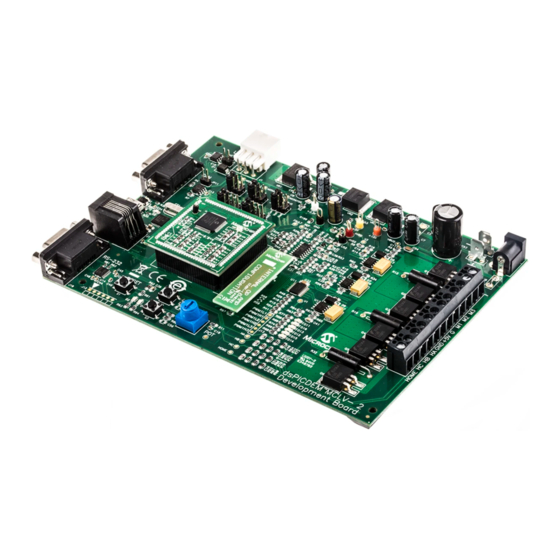
OVERVIEW OF THE dsPICDEM MCLV-2 DEVELOPMENT BOARD Figure 1-1 shows a simplified block diagram of the dsPICDEM MCLV-2 Development Board. The board includes various circuitry to perform the following functions: • Drive a three-phase inverter that powers the motor phase windings •... -
Page 14: Features Overview
- ICSP™ connector for programming a dsPIC DSC or PIC24 MCU (J12) - RJ11 connector for programming a dsPIC DSC or PIC24 MCU (J11) - ICSP connector for programming the PIC18LF2450 USB to UART Bridge (J9) 2012 Microchip Technology Inc. DS52080A-page 14... - Page 15 LED D2 LED D17 HOME Safe Current U5:C Limit HOME FAULT_MC IMOTOR_SUM U5:A RS232 IMOTOR2 V_M3 U5:B Potential V_M2 Divider V_M1 IMOTOR1 REC_NEUTR JP1-JP3 V_M3 V_M2 Matrix Board V_M1 V_M3 V_M2 V_M1 REC_NEUTR 2012 Microchip Technology Inc. DS52080A-page 15...
- Page 16 MCLV-2 Development Board User’s Guide NOTES: 2012 Microchip Technology Inc. DS52080A-page 16...
-
Page 17: Chapter 2. Hardware Overview
MCLV-2 DEVELOPMENT BOARD USER’S GUIDE Chapter 2. Hardware Overview This chapter describes the hardware components of the dsPICDEM MCLV-2 Development Board. Topics covered include: • PIM Configuration • Board Connectors • User Interface Hardware Power for the control circuits and DC bus on the board is provided through a +24V power supply attached to the Power Connector terminal (J2) or the Auxiliary Power Tab Fast-On Connector terminals (BP1-BP2). -
Page 18: Pim Configuration
MCLV-2 Development Board User’s Guide PIM CONFIGURATION Table 2-1 summarizes the PIM pinout for the dsPICDEM MCLV-2 Development Board. TABLE 2-1: dsPICDEM MCLV-2 DEVELOPMENT BOARD PIM PINOUT FUNCTIONALITY PIM Pin # Signal Name Pinout Description Routed via Matrix Board... -
Page 19: Hardware Overview
Hardware Overview TABLE 2-1: dsPICDEM MCLV-2 DEVELOPMENT BOARD PIM PINOUT FUNCTIONALITY PIM Pin # Signal Name Pinout Description Routed via Matrix Board UART Receive UART Transmit USB_TX UART Transmit (connected directly to U7) USB_RX UART Receive (connected directly to U7) -
Page 20: Board Connectors
MCLV-2 Development Board User’s Guide BOARD CONNECTORS Table 2-2 describes the hardware connection between MPLAB ICD 3 or MPLAB REAL ICE™ In-Circuit Emulator, the power supply, and the dsPICDEM MCLV-2 Development Board connectors. TABLE 2-2: BOARD CONNECTORS Number Designator... - Page 21 Hardware Overview 2.2.1 Input Power Connector (J2, BP1-BP2) The dsPICDEM MCLV-2 Development Board receives the power for control circuits and the DC bus from a +24V power supply. It is connected to the board through J2 or BP1-BP2 points. 2.2.2...
- Page 22 Motor feedback signal 1 MONITOR_2 Motor feedback signal 2 MONITOR_3 Motor feedback signal 3 Phase 1 current Phase 2 current IBUS Bus current +3.3V (digital) GND (digital) +15V Analog ground Bus voltage (downscaled) 2012 Microchip Technology Inc. DS52080A-page 22...
- Page 23 2.2.10.1 INTERNAL AND EXTERNAL OP AMP MATRIX BOARDS The dsPICDEM MCLV-2 Development Board uses discrete op amps (U5) to amplify the shunt resistor signals. Alternatively, some PIC24 MCUs or dsPIC DSCs are designed with op amps on-board that can be used for this purpose. To accommodate these two basic configurations, the dsPICDEM MCLV-2 Development Board includes two matrix boards.
-
Page 24: Selecting A Power Supply For The Development Board
When J3 is installed, VR3 must be removed to avoid damage to the 15V regulator. USER INTERFACE HARDWARE 2.4.1 Jumpers The dsPICDEM MCLV-2 Development Board has nine jumpers that configure the functionality of the board. Figure 2-3 shows the jumper settings and... - Page 25 Connects UART transmit line to Tx TABLE 2-7: ADDITIONAL JUMPERS Designator Functions Bypass 15V regulator connector for gate driver IC LIN master select Connects BP1-BP2/J2 to motor connector block J7 JP11 CAN end enable 2012 Microchip Technology Inc. DS52080A-page 25...
- Page 26 MCLV-2 Development Board User’s Guide 2.4.2 Push-Buttons, LEDs, Bus Resistors and Potentiometers The dsPICDEM MCLV-2 Development Board consists of the following items: • Two push-buttons • One potentiometer • Six LEDs for PWM • Two LEDs for debugging purposes •...
-
Page 27: Chapter 3. Running A Bldc Motor Using A Sensorless Algorithm
Chapter 3. Running a BLDC Motor Using a Sensorless Algorithm This chapter describes how to set up the dsPICDEM MCLV-2 Development Board in the Internal Op amp configuration to run a BLDC motor using the Single-Shunt Current Reconstruction Algorithm using a dsPICDEM™ MCLV-2 Development Board. The algorithm is described in AN1299 “Single-Shunt Three-Phase Current Reconstruction... -
Page 28: Dspicdem Mclv-2 Development Board Setup
MCLV-2 Development Board User’s Guide dsPICDEM MCLV-2 DEVELOPMENT BOARD SETUP The following procedure describes how to set up the dsPICDEM MCLV-2 Development Board: WARNING The dsPICDEM MCLV-2 Development Board is intended to drive the three-phase BLDC or PMSM motor. Before connecting the motor, make sure that the power rating... - Page 29 Digital Signal Controllers” (DS01078) • AN1017, “Sinusoidal Control of PMSM Motors with dsPIC30F DSC” (DS01017) The source code referred in these application notes is available from the Microchip web site (www.microchip.com). 2012 Microchip Technology Inc. DS52080A-page 29...
- Page 30 MCLV-2 Development Board User’s Guide NOTES: 2012 Microchip Technology Inc. DS52080A-page 30...
- Page 31 MCLV-2 Development Board Schematic (Sheet 7 of 7)” Figure A-8: “Internal Op amp Configuration Matrix Board Schematic” Figure A-9: “External Op amp Configuration Matrix Board Schematic” ™ Figure A-10: “dsPICDEM MCLV-2 Development Board Layout” 2012 Microchip Technology Inc. DS52080A-page 31...
- Page 32 ™ FIGURE A-1: dsPICDEM MCLV-2 DEVELOPMENT BOARD SCHEMATIC (SHEET 1 OF 7) YELLOW 100-pin PIM Header YELLOW Note: For pin descriptions, please see Table 2-1, “dsPICDEM MCLV-2 Development Board PIM Pinout Functionality,” on page 18.
- Page 33 ™ FIGURE A-2: dsPICDEM MCLV-2 DEVELOPMENT BOARD SCHEMATIC (SHEET 2 OF 7) Note 1: All resistors on this page must be 1%. Supply Voltage should be AV for MCP6024.
- Page 34 ™ FIGURE A-3: dsPICDEM MCLV-2 DEVELOPMENT BOARD SCHEMATIC (SHEET 3 OF 7) 1 HIN 2 LIN 3 COM 4 LO 1 HIN 2 LIN 3 COM 4 LO 1 HIN 2 LIN 3 COM 4 LO 470uF...
- Page 35 ™ FIGURE A-4: dsPICDEM MCLV-2 DEVELOPMENT BOARD SCHEMATIC (SHEET 4 OF 7)
- Page 36 ™ FIGURE A-5: dsPICDEM MCLV-2 DEVELOPMENT BOARD SCHEMATIC (SHEET 5 OF 7)
- Page 37 ™ FIGURE A-6: dsPICDEM MCLV-2 DEVELOPMENT BOARD SCHEMATIC (SHEET 6 OF 7)
- Page 38 ™ FIGURE A-7: dsPICDEM MCLV-2 DEVELOPMENT BOARD SCHEMATIC (SHEET 7 OF 7)
-
Page 39: Schematics And Layout
SHUNT_HIGH_2 PIM_IB+ REC_NEUTR PIM_REC_NEUTR MONITOR_1 PIM_MONITOR_1 MONITOR_2 PIM_MONITOR_2 MONITOR_3 PIM_MONITOR_3 VBUS PIM_VBUS IMOTOR_SUM PIM_IMOTOR_SUM IMOTOR1 PIM_IMOTOR1 IMOTOR2 PIM_IMOTOR2 PIM_POT PIM_FLT_OUT1 PIM_FLT_OUT2 PIM_GEN1 PIM_GEN2 V_M1 PIM_V_M1 V_M2 PIM_V_M2 V_M3 PIM_V_M3 Matrix Board Header MCLV 2012 Microchip Technology Inc. DS52080A-page 39... - Page 40 SHUNT_HIGH_2 PIM_IB+ REC_NEUTR PIM_REC_NEUTR MONITOR_1 PIM_MONITOR_1 MONITOR_2 PIM_MONITOR_2 MONITOR_3 PIM_MONITOR_3 VBUS PIM_VBUS IMOTOR_SUM PIM_IMOTOR_SUM IMOTOR1 PIM_IMOTOR1 IMOTOR2 PIM_IMOTOR2 PIM_POT PIM_FLT_OUT1 PIM_FLT_OUT2 PIM_GEN1 PIM_GEN2 V_M1 PIM_V_M1 V_M2 PIM_V_M2 V_M3 PIM_V_M3 Matrix Board Header MCLV 2012 Microchip Technology Inc. DS52080A-page 40...
-
Page 41: Appendix A. Schematics And Layout
Schematics and Layout ™ FIGURE A-10: dsPICDEM MCLV-2 DEVELOPMENT BOARD LAYOUT 2012 Microchip Technology Inc. DS52080A-page 41... - Page 42 MCLV-2 Development Board User’s Guide NOTES: 2012 Microchip Technology Inc. DS52080A-page 42...
-
Page 43: Appendix B. Electrical Specifications
By default, the board uses D PAK Power MOSFETs. It also supports the TO-220 packages. If the TO-220 Power MOSFETs are used, additional heat sink can be mounted on the MOSFETs, if required. 2012 Microchip Technology Inc. DS52080A-page 43... -
Page 44: Worldwide Sales And Service
Thailand - Bangkok Tel: 86-29-8833-7252 Tel: 66-2-694-1351 Toronto Fax: 86-29-8833-7256 Fax: 66-2-694-1350 Mississauga, Ontario, Canada China - Xiamen Tel: 905-673-0699 Tel: 86-592-2388138 Fax: 905-673-6509 Fax: 86-592-2388130 China - Zhuhai Tel: 86-756-3210040 11/29/11 Fax: 86-756-3210049 2012 Microchip Technology Inc. DS52080A-page 44...
Need help?
Do you have a question about the dsPICDEM MCLV-2 and is the answer not in the manual?
Questions and answers