AGFEO AS 200 IT Installation Manual
Hide thumbs
Also See for AS 200 IT:
- Reference manual (36 pages) ,
- Installation manual (24 pages) ,
- Reference manual (36 pages)
Table of Contents
Advertisement
Quick Links
Download this manual
See also:
Reference Manual
Advertisement
Table of Contents

Related Manuals for AGFEO AS 200 IT


Summary of Contents for AGFEO AS 200 IT
- Page 1 Installation Manual PBX System AS 200 IT...
-
Page 2: About This Manual
SO Bus. In addition you may connect up to two digital AGFEO System Phones to each SO Bus. Any other use of the telephone system which is not listed or described is prohibited. -
Page 3: Table Of Contents
The AS 200 IT Telephone System ......................4 Tecnical Data ............................5 Installation of the System on telescopic tracks ..................5 Opening the Cover on the AS 200 IT ...................... 6 Removing the Patch Panel ........................6 Installation Note ............................ 6 Inserting the Modules ........................... -
Page 4: The As 200 It Telephone System
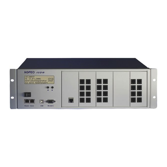
AS 200 IT The AS 200 IT Telephone System The AGFEO AS 200 IT is a modular ISDN telephone system in a 19 inch rack housing with a temperature controlled cooling fan. The current operating temperature will be displayed when the system status is idle. -
Page 5: Tecnical Data
Installation of the System on telescopic tracks The AGFEO AS 200 IT from Serial Number 001301 can be fixed to Telescopic Tracks from Accuride. These tracks enable the system to be drawn from the IT cabinet and giving easy access to all modules. -
Page 6: Opening The Cover On The As 200 It
AS 200 IT Installation Note After disassembling the mounting brackets from the AS 200 IT, please be aware to reassemble the screws before switching on the AS 200 IT. Opening the Cover on the AS 200 IT Remove the screws on the side of the housing cover. Slide the cover backwards and remove it. -
Page 7: Inserting The Modules' Patch Panels
AS 200 IT Inserting the Modules' Patch Panels To insert the patch panel, hook the notch on the bottom edge into the appropriate groove. Push the cable through the opening in the front plate as shown in the photograph. Then shut the front plate and screw it tight using the knurled screws. -
Page 8: Patch Panel Of Modules
AS 200 IT Patch Panel of Modules The correct patch panel is required for each AGFEO standard module so that the External module's terminals rest flush against the patch panel. Please refer to the reverse side of each patch panel to identify which module it has been designed Pin 1 for. -
Page 9: Patch Panel Of The Al-Module 4504
AS 200 IT Patch Panel of the AL-Module 4504 Pin 1 Analogue Trunk Line 1 Analogue Trunk Line 3 Analogue Trunk Line 2 Analogue Trunk Line 4 Patch Panel of the S0-Module 540 Pin1 Plug 1 switchable S0-1 Rear side of... -
Page 10: Patch Panel Of The T-Module 508
AS 200 IT Patch Panel of the T-Module 508 Pin 1 Plug 1 Extension 5 Extension 1 Extension 6 Extension 2 Extension 7 Extension 3 Pin 1 Plug 2 Extension 8 Extension 4 For notes referring to the plugs, please read “Connecting Patch Panel to Modules” on Page 7. -
Page 11: T-Shaped S0 Bus
AS 200 IT T-Shaped S0 Bus Until now, AGFEO systems were not designed for split internal (t-shaped) S0 buses. The AS 100 IT now provides for this. However, the termination resistance assignment required has changed in this respect. While the PABX and the outlet furthest away have to be terminated with 100 Ohms, with t-shaped wiring, the PABX has no terminating resistance. -
Page 12: Leds Of The As 200 It
AS 200 IT LEDs of the AS 200 IT LED 1 LED 2 LED 3 LED 4 Permanentely Lit Flashes LED 1 (red) System is operational System being initialised LED 2 (green) Data being transferred System is connected to the... -
Page 13: Display Of The As 200 It
Display of the AS 200 IT You can read the system status, slot configuration and module configuration from the display on the AS 200 IT. Simply use the two arrow buttons on the housing to do so. AS 200 IT standby display AS 200 IT Di 01.01.2002 00:00... -
Page 14: Declaration Of Confirmity
AS 200 IT Declaration of Confirmity... - Page 16 Ident no. 1101331 Subject to change without notice. No liability can be AGFEO GmbH & Co. KG accepted for errors contained in Gaswerkstr. 8 this document. D-33647 Bielefeld Printed in Germany Internet: http://www.agfeo.com...
Need help?
Do you have a question about the AS 200 IT and is the answer not in the manual?
Questions and answers