Table of Contents
Advertisement
Quick Links
Download this manual
See also:
Maintenance Manual
Advertisement
Table of Contents

Subscribe to Our Youtube Channel
Related Manuals for MIMAKI UJF-3042FX


Summary of Contents for MIMAKI UJF-3042FX
- Page 1 MIMAKI ENGINEERING CO., LTD. URL: http://eng.mimaki.co.jp/ D202217-20...
-
Page 2: Table Of Contents
TABLE OF CONTENTS CAUTION ................. vi DISCLAIMER OF WARRANTY ........vi Requests ................vi FCC Statement (USA) ............vi Interference to televisions and radios.......vi CDRH REGULATION............vii Foreword .................viii On this operation manual ..........viii For safe operation ............ix Symbols................ix Position of the warning label..........xvi How to Read This Operation Manual ...... - Page 3 Starting the drawing operation........2-9 Interruption of drawing..........2-10 Checking drawing data that is being received or has been received ........... 2-10 When [! WORK High] is displayed......2-11 If you open the cover during drawing ...... 2-11 Turning the power OFF......... 2-12 CHAPTER 3 Useful Function Changing origin............
- Page 4 Setting weight of the empty cartridge.......3-30 Setting Key buzzer ...........3-31 Setting radiator pump..........3-32 Setting the flushing level before printing ....3-33 CHAPTER 4 Maintenance Routine maintenance..........4-2 When this machine is left unused for a long time..4-2 Precautions in cleaning ..........4-2 Cleaning exterior surfaces .........4-3 Cleaning the table ............4-3 Ink cartridge.............
- Page 5 CHAPTER 5 In Case of Trouble Before taking a phenomenon as a trouble ....5-2 The machine cannot be energized ......5-2 The machine cannot perform printing......5-2 If image quality declines ..........5-3 Resolving nozzle clogging ......... 5-3 Troubles for which error messages are given on the LCD ............
-
Page 6: Caution
• In the case where MIMAKI-recommended cable is not used for connection of this device, limits provided by FCC rules can be exceeded. To prevent this, use of MIMAKI-recommended cable is essential for the connection of this machine. -
Page 7: Cdrh Regulation
CAUTION CDRH REGULATION The Center for Devices and Radiological Health for the U.S. Food and Drug Administration Implement regulations for laser products. The sentence of “This product complies with 21 CFR chapter I and subchapter J” indicates compliance with the CDRH regulations and is labeled on the product when marketed in the United States. -
Page 8: Foreword
Read this Operation Manual carefully and make the most effective use of your printer. On this operation manual • This Operation Manual describes the operation and maintenance of Model UJF-3042FX Color Ink Jet Printer (hereinafter referred to as the machine). -
Page 9: For Safe Operation
For safe operation Symbols Symbols are used in this Operation Manual for safe operation and for prevention of damage to the machine. The indicated sign is different depending on the content of caution. Symbols and their meanings are given below. Please follow these instructions as you read this manual. Examples of symbols Failure to observe the instructions given with this symbol can result in death or serious injuries to personnel. - Page 10 WARNING • Be sure to setup the appropriate air-moving system in case of using this machine in a closed room or a room with bad ventilation. Cautions for constructing exhaust outlet Please observe the following cautions to avoid breakdown of this machine. (1) The opening area of the exhaust outlet requires more than half of the duct entrance area.
- Page 11 For safe operation Never do the following WARNING Do not disassemble or remodel the machine Handling of ink cartridges • Never disassemble or remodel this machine and • Some of the ingredients (UV Curing initiator) the ink cartridge. have toxic consequences to aquatic life. Avoid Disassembling or remodeling any of them will leak into water system or sewage containing result in electric shocks or breakdown of this...
- Page 12 WARNING Wearing protective devices • When cleaning the suction nozzle, which may scatter ink, be sure to wear safety glasses and gloves, or ink and cleaning solution might enter your eyes or ink and cleaning solution put on your hands might make your hands rough.
-
Page 13: Precautions For Use
For safe operation Precautions for use CAUTION Protection against dust Periodic exchange parts • It is strongly recommended to use the machine • There are some parts which must be periodically in a room that is not dusty. replaced. Contract with distributors or dealers Set the Refresh level 2 or 3 when in bad for maintenance. - Page 14 • The LED UV performance and service life are significantly affected by the UV irradiation and UV power supply units used. Never use those UV devices other than those recommended by Mimaki. We would take no responsibility for any troubles caused through the use of a UV devices not recommended by Mimaki.
-
Page 15: Precautions For Installation
For safe operation Precautions for installation CAUTION A place exposed to direct A place where temperature and A place that is not horizontal sunlight humidity varies significantly •Use the machine under the following environment. Operating environment : 20 ~ 35 ℃ (68 to 95 °F) 35 ~... -
Page 16: Position Of The Warning Label
Position of the warning label Warning labels are adhered on this machine. Be sure to fully understand the warnings given on the labels. In the case where any of the warning label has become so soiled that the warning message is illegible or has come off, purchase a new one from your local distributor or our office. - Page 17 Position of the warning label Order No. Label Order No. Label (1) M907328 (7) M901549 (2) M904325 (8) M905980 (3) M904813 (4) M903226 (5) M907327 (9) M902535 (6) M903330 xvii...
-
Page 18: How To Read This Operation Manual
How to Read This Operation Manual This manual provides the explanation about the displayed characters and used keys on the “Display Panel” in addition to the operation procedures. Proceed operations confirming them while using. These are what we want you This explains the to know in advance. - Page 19 CHAPTER 1 Before Use This chapter describes the parts name and setting procedures before use. Installing the machine ............1-2 Where to install the machine ............1-2 Moving this machine ..............1-3 Configuration and Function..........1-4 Front ...................1-4 Rear ....................1-4 Operation Panel ................1-5 Carriage ..................1-6 EMERGENCY SWITCH ..............1-6 Connecting the cables............
-
Page 20: Installing The Machine
Installing the machine Where to install the machine Secure sufficient space for installation before assembling this machine. Decide the place considering the size of the machine and a space required for drawing. Width Depth Height Total Weight 1200 mm 1090 mm 770mm Approx.113 kg 500 mm or more... -
Page 21: Moving This Machine
Installing the machine Moving this machine Move this machine as follows when this machine is required to move on the step-free same floor. • When moving this machine, take care not to give a significant impact on • When moving this machine, keep it as flatly as possible. Do not move it on its side. -
Page 22: Configuration And Function
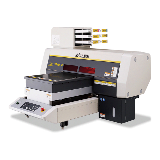
Configuration and Function Front Ink station Insert ink cartridges here.( P.1-8) Carriage ( P.1-6) Table ( P.2-4) Set media on it. Y-bar There are absorbing holes on the table so that media is absorbed Moves on the table at drawing. when vacuum is ON. -
Page 23: Operation Panel
Configuration and Function Operation Panel The operation panel is used for setting of drawing method and each operation. POWER Lamp VACUUM Lights when the power is ON. Press to switch ON/OFF of the vacuum. TABLE TEST Press to raise or lower the table. Press to start the test drawing. -
Page 24: Carriage
Configuration and Function Carriage A print head for drawing, LED UV device, and a light pointer in the print head cover are mounted on the carriage. EMERGENCY SWITCH When stopping the machine for safety reason, press the switch. One EMERGENCY switch is placed on the front face of the machine. -
Page 25: Connecting The Cables
Connecting the cables Connecting the USB2.0 interface cable Connect a computer to this machine with the USB2.0 interface cable. • Prepare the USB2.0 interface cable. (USB2.0 interface cable is not supplied with this machine.) • Your RIP is required to support USB2.0 interface. •... -
Page 26: Setting Of Ink Cartridge
Setting of ink cartridge Use the ink cartridge inserting it into the ink station. Kinds of ink that can be used Ink Type Color Magenta UV Ink Cyan Yellow Black White Clear Cleaning cartridge *1. To be used when the head is cleaned. Each color is displayed on the LCD as follows: Display Color... - Page 27 • Never disassemble the ink cartridge. • Never refill the ink cartridge with ink. Refilling the ink cartridge can cause a trouble. Remember that Mimaki assumes no responsibility for any damage caused by the use of the ink cartridge replenished with ink.
-
Page 28: About Media
About Media The sizes of media that can be used and the method of handling are described here. The sizes of media that can be used 300 mm Maximum width Maximum length 420 mm 300 mm Max. drawing width 420 mm Max. -
Page 29: Menu Mode
Menu mode This machine has three modes. Each mode is described below. Local Mode Local mode is a mode in drawing preparation state. All keys are available. Receiving of data from the computer is allowed, however, drawing is not executed. The following operations are allowed in the local mode. - Page 30 1-12...
- Page 31 CHAPTER 2 Basic Operations The procedure from preparation of ink and media to the execution of drawing, and setting methods are explained. Operation flow..............2-2 Turning the power ON ............2-3 Setting the media ..............2-4 Set the media in another method ..........2-5 Test drawing.................
-
Page 32: Operation Flow
Operation flow Turning the power ON See "Turning the power ON" P.2-3) Setting the media See "Setting the media" ( P.2-4) Test drawing See "Test drawing" ( P.2-6) Execution of head cleaning See "Execution of head cleaning" P.2-8) Drawing an image from source See "Drawing an image from source data"... -
Page 33: Turning The Power On
Turning the power ON • When the power is turned ON, the Y-bar moves. To avoid injuries, keep your hands away from the table. Press the power button. • Press the power button on the left side of the operation panel to light. -
Page 34: Setting The Media
Setting the media • To avoid lifting of media, turn ON the adsorption fan after setting media. • If, within the adsorption area, there are suction holes not closed by the media, close such suction holes placing thin sheet form material such as paper, film or tape. •... -
Page 35: Set The Media In Another Method
Setting the media Set the media in another method You can move the Y bar to the rear so that you may set the media easier. Press the key in the local mode. FUNCTION < L O C A L > Press the key. -
Page 36: Test Drawing
Test drawing Make test drawing in the specified direction to check whether there is nozzle clogging or other drawing failures (such as wearing or missing). Check before starting • Is media set? ( P.2-4) • Is origin point set? ( P.3-2) test drawing Press the... - Page 37 Test drawing Abnormal patterns Normal pattern Nozzle drop out Nozzle missing Deflection Many lines are missing. The lines are missing as if the The distance between the teeth are lost. lines is narrowing or double lines are formed.
-
Page 38: Execution Of Head Cleaning
Execution of head cleaning When a correct pattern is not obtained in the test drawing, perform the head-cleaning. As for the head cleaning, the following 4 types are available. To be used if ten odd numbers of the lines are missing when the test pattern is made. normal Suction and wiping will be performed. -
Page 39: Drawing An Image From Source Data
Drawing an image from source data Starting the drawing operation • If the temperature of the head has not reached the predetermined value, a message is displayed. Drawing is not allowed in such cases. When the display is disappeared, drawing can be started. •... -
Page 40: Interruption Of Drawing
Interruption of drawing To interrupt drawing, stop the drawing operation and erase the received data from the machine. Press the key while drawing. REMOTE < L O C A L > • Drawing operation stops. • When data is transmitted from the computer, the computer stops transmission of data. -
Page 41: When [! Work High] Is Displayed
Drawing an image from source data When [! WORK High] is displayed When [! WORK High] is displayed on the screen and the drawing operation stops during drawing, restart drawing with the procedures below: E R R O R 5 0 5 ! WO R K H i g h •... -
Page 42: Turning The Power Off
Turning the power OFF To turn off, check first whether or not there is data received and there remains data that has not yet been output in the machine. Turn the power of the connected computer off. Press the power button to cut the power. When this machine is not used for a long time, execute the following: (1) Press the power button. - Page 43 CHAPTER 3 Useful Function Items required for using this machine conveniently, such as an ink replacing method or a cleaning manner, are described. Changing origin ........3-2 Setting the mode of the LED UV ....3-16 Increasing cumulative UV irradiation Changing origin with JOG keys ....3-2 when the number of passes is low ..3-17 Changing origin with FUNCTION menu ...
-
Page 44: Changing Origin
Changing origin The default origin position can be changed. There are following 2 changing methods. Changing with the JOG keys Changing with the “ORIGIN” in the FUNCTION menu Changing origin with JOG keys Press the keys O R I G I N S E T in the local mode. -
Page 45: Changing Origin With Function Menu
Changing origin Changing origin with FUNCTION menu To precisely set the origin of coordinates, set its X- and Y- coordinates from the FUNCTION menu. This setting value becomes the origin position (0, 0). Press the key in the local mode. FUNCTION <... -
Page 46: Setting The Head Height
Setting the Head Height Media thickness, Head gap, and Table height can be changed. Setting the media thickness If the media thickness is changed, Table Height is also changed. Press the key in the local mode. FUNCTION < L O C A L > Select the [HEAD HEIGHT] by pressing the F U N C T I O N key, and press the... -
Page 47: Setting The Head Gap
Setting the Head Height Setting the head gap If the head gap is changed, Table Height is also changed. Press the key in the local mode. FUNCTION < L O C A L > Select the [HEAD HEIGHT] by pressing the F U N C T I O N key, and press the key. -
Page 48: Setting The Table Height
Setting the table height If the table height is changed, Media Thickness is also changed. Press the key in the local mode. FUNCTION < L O C A L > Select the [HEAD HEIGHT] by pressing the F U N C T I O N key, and press the key. -
Page 49: Gap Check
Setting the Head Height Gap check Select operation when obstacles are detected during drawing. Press the key in the local mode. FUNCTION < L O C A L > Select the [HEAD HEIGHT] by pressing the F U N C T I O N key, and press the key. -
Page 50: Perform Setting To Reduce Stripes Between Passes
Perform setting to reduce stripes between passes What is the MAPS Function? If performing media correction does not resolve feeding stripes, use the MAPS (Mimaki Advanced PassSystem) function to disperse the pass boundary to make the feeding stripes less visible. - Page 51 Perform setting to reduce stripes between passes Press the key. MA PS 2 ENTER P A T T ERN : 1 • When selecting the “AUTO” in the Step 7, back to the step 4. • When selecting the “MANUAL” in the Step 7, proceed to the step 9. Set the pattern for the color ink.
-
Page 52: Other Useful Functions
Other useful functions Data clear Erase the data not required for this machine with the following operation. Press the key in the local mode. DATACLEAR < L O C A L > Press the key. ENTER D A T A C L E A R <... -
Page 53: Proceed With Drawing That You Suspended
Other useful functions Proceed with drawing that you suspended When you open the cover during printing data, drawing is suspended. In such a case, you can proceed with it continuously by performing the procedures below. • When you suspended test drawing, you cannot continue it. •... -
Page 54: Alternative Nozzles For Printing, When Nozzles Missing Can Not Be Improved
Alternative nozzles for printing, when nozzles missing can not be improved NOZZLE RECOVERY: When nozzles missing can not be improved at specific points, other good nozzles can be used as alternatives for printing. Press the key in the local mode. FUNCTION <... - Page 55 Other useful functions Register the Nozzle number that needs NOZZLE N O Z Z L E R E C O V E R Y RECOVERY and then press key. H 1 - M N G 3 : 1 4 6 ENTER •...
-
Page 56: Checking Ink Landing Displacement
Other useful functions Checking ink landing displacement You can check for ink landing displacement from causes such as the equipment table shaking. (Supported from the firmware ver.3.80) Press the key in the local mode. FUNCTION < L O C A L > Select the [MAINTENANCE] by pressing the F U N C T I O N key, and press the... -
Page 57: Various Settings
Various settings Setting the print method Set items for printing. Press the key in the local mode. FUNCTION < L O C A L > Select the [SET UP] by pressing the F U N C T I O N key, and press the key. -
Page 58: Setting The Mode Of The Led Uv
Setting the mode of the LED UV The mode of the LED UV may be set in 3 stages. This setting is made when the media vulnerable to the heat is used or when the test drawing is made in which the lighting of the LED UV is not desired. -
Page 59: Increasing Cumulative Uv Irradiation When The Number Of Passes Is Low
Various settings Increasing cumulative UV irradiation when the number of passes is low When the number of passes is low (720x600: 8 passes or less, 720x900: 12 passes or less, 720x1200: 8 passes or less), cumulative UV light quantity irradiated to the discharged ink is smaller, which may cause insufficient UV curing for some media type. -
Page 60: Setting Of Priority
Setting of priority Select priority of setting of this machine or that of the computer on the following items respectively. Items to be selected : Print mode / Feed compensation / Ink layers / Logical seek / Refresh Press the key in the local mode. -
Page 61: Setting The Mode Of The Fan Mode
Various settings Setting the mode of the fan mode Set whether you perform vacuum automatically or with the user-specified operation. When you set it to “AUTO”, vacuum is made to ON automatically before drawing. When you set it to “MANUAL”, ON/OFF of vacuum follows the user setting. (Supported from the firmware ver.3.00) Press the key in the local... -
Page 62: Setting The Work Change
Setting the work change Set whether to return to the local mode or keep the remote mode after online drawing. Press the key in the local mode. FUNCTION < L O C A L > Press the [SET UP] by pressing the F U N C T I O N key, and press the key. -
Page 63: Setting The Ink Weight
Various settings Setting the ink weight Enter the weight when after filling ink or INK LVL LOW or INK LVL END is detected. This machine recalculates remaining amount of ink and writes the value into the IC chip. (600ml ink only) Press the key in the local mode. -
Page 64: Changing Language Display On The Screen
Changing language display on the screen Display language can be selected between Japanese and English. Press the key in the local mode. FUNCTION < L O C A L > Select the [DISPLAY] by pressing the F U N C T I O N key, and press the key. -
Page 65: Output The Setting List
Various settings Output the setting list Keep the list for customer’s record or send it by the fax at inquiry on the maintenance. Set a larger media than the legal size. ( P.2-4) Press the key in the local mode. FUNCTION <... -
Page 66: Displaying Machine Information
Displaying machine information Press the key in the local mode. FUNCTION < L O C A L > Select the [MAINTENANCE] by pressing the F U N C T I O N key, and press the key. M A I N T E N A N C E <... - Page 67 Various settings About Displayed Information This section describes how to read displayed information. ERROR HISTORY [ 0 0 0 0 0 ] E R R O R 6 0 2 Displaying the I N K E N D 2 0 1 4 / 0 1 / 2 3 1 2 : 3 4 : 5 6 occurrence date The error occurrence date and...
-
Page 68: Other Useful Settings
Other useful settings Change settings according to need. Press the key in the local mode. FUNCTION < L O C A L > Select the [SET UP] by pressing the F U N C T I O N key, and press the key. -
Page 69: Initializing Settings
Various settings Initializing settings Press the key in the local mode. FUNCTION < L O C A L > Select the [SET UP] by pressing the F U N C T I O N key, and press the key. WO R K S E T <... -
Page 70: Setting Time
Setting time Press the key in the local mode. FUNCTION < L O C A L > Select the [MACHINE SET] by pressing the F U N C T I O N key, and press the key. M A C H I N E S E T <... -
Page 71: Setting Mm/ Inch
Various settings Setting mm/ inch Set the unit to be used on this machine. Press the key in the local mode. FUNCTION < L O C A L > Select the [MACHINE SET] by pressing the F U N C T I O N key, and press the key. -
Page 72: Setting Weight Of The Empty Cartridge
Setting weight of the empty cartridge Enter weight of the empty cartridge. It is used for recalculating remaining amount of ink. (600ml ink only) Press the key in the local mode. FUNCTION < L O C A L > Press the [MACHINE SET] by pressing the F U N C T I O N key, and press the key. -
Page 73: Setting Key Buzzer
Various settings Setting Key buzzer Set the buzzer sound when keys are pressed. Press the key in the local mode. FUNCTION < L O C A L > Select the [MACHINE SET] by pressing the F U N C T I O N key, and press the key. -
Page 74: Setting Radiator Pump
Setting radiator pump On UJF-3042 and UJF-3042FX, if the noise of the cooling pump for LED UV unit become louder after updating the firmware to the version 3.10 or later, change the setting as follows. (Supported from the firmware ver.3.10) Press the key in the local mode. -
Page 75: Setting The Flushing Level Before Printing
Various settings Setting the flushing level before printing When using a clear acrylic jig and so on, the ink may splash on the print result as the ink on the nozzles thickens due to stray light. If this happens, increase the flushing amount before printing to prevent ink from splashing. (Supported from the firmware ver.4.00) Press the key in the local mode. - Page 76 3-34...
- Page 77 CHAPTER 4 Maintenance Items required for using this machine conveniently, such as an ink replacing method or a cleaning manner, are described. Routine maintenance ......4-2 When the waste ink is full....4-15 When this machine is left unused Disposing of the ink in the waste ink tank ..4-15 for a long time ...........
-
Page 78: Routine Maintenance
Routine maintenance Be sure to conduct maintenance works for the machine depending on operation frequency or periodically so as to use the machine for a long time while keeping its drawing accuracy. When this machine is left unused for a long time •... -
Page 79: Cleaning Exterior Surfaces
Routine maintenance Cleaning exterior surfaces If exterior surfaces of the machine is dirty, dampen a soft cloth with water or a neutral detergent diluted with water, squeeze it and wipe the surfaces. Cleaning the table The table is easy to become dirt with lint, paper dust or the like after cutting media. For a conspicuous stain, wipe it off with a soft-hair brush, a dry cloth, a paper towel or the like. -
Page 80: Ink Cartridge
Ink cartridge Replacing with a new ink cartridge Replacing of ink cartridges is required in the following cases. Display Outline The ink in the ink cartridge is low. < L O C A L > ?Drawing can be continued, but the ink may end during the drawing. Early I N K N E N D M _ _ _ _ _... -
Page 81: Setting The Ink Set
Ink cartridge Setting the ink set Set the ink set when ink type is changed. Contact a distributor in your district or our office to call for service. When you replace another kind of ink, wash all heads. For replacement between the same inks, the process (washing and filling) flow is as below: Ink set before replacement Ink set after replacement Procedure... -
Page 82: Press The Enter Key
• The step 5 to 10 is displayed when washing is required. Pull out the ink cartridges from the ink station. W A S H R E M O V E C A R T R I D G E •... - Page 83 Ink cartridge When a screen shown on the right appears, put 5 cc T U B E C L E A N I N G of the washing liquid into the air vent tube to wash. C O M P L E T E D : e n t •...
-
Page 84: Ink Cartridge Trouble
Ink cartridge trouble When an ink cartridge trouble is detected, a warning message appears and printing, cleaning and all other activities that use ink are deactivated. In this case, replace the ink cartridge in question immediately. • Do not leave the ink cartridge without replacing for a long time as this will cause the nozzle clogging and the printer must be repaired by a service person. -
Page 85: Shaking The White Ink Cartridge
Ink cartridge Shaking the white ink cartridge Shake the white ink cartridge when starting the device or when the following screen is displayed. (Supported from the firmware ver.4.10) P l e a s e s h a k e W C r t r g P R E S S <... -
Page 86: 600Ml Ink Cartridge
600ml Ink cartridge To use the 600ml ink cartridges, register the case weight (this page) and the cartridge weight (next page). Please prepare your scale (which can weigh up to 1200g in 1g). Registering the case weight Firstly register the case weight in the following procedures. For the 600ml cartridges, this machine recalculates remaining amount of ink from a registered case weight. -
Page 87: Registering The Cartridge Weight
600ml Ink cartridge Registering the cartridge weight After filling ink into the 600ml cartridge, register the cartridge weight. After filling ink, press the key several times. Press the key. I n k L e v e l S e t M _ _ _ _ _ _ _ E x e c <... -
Page 88: Registering The Cartridge Weight (After Lvl Low / Lvl End)
600ml Ink cartridge Registering the cartridge weight (After LVL LOW / LVL END) The 600ml cartridge becomes level low when ink remains 60ml or less, and level end when ink remains 25ml or less. In this case, register the cartridge weight on the entry screen that is displayed. The level low or level end cartridge cannot be used until the weight is entered. -
Page 89: Avoiding Dripping Of Ink Droplet At Printing
Avoiding dripping of ink droplet at printing Ink droplets from the mist at drawing may arise on the bottom of the carriage. As the ink droplets may drip and stain the media or cause blur or dot missing, clean the bottom of the carriage periodically. •... - Page 90 Avoiding dripping of ink droplet at printing Dip the cleaning swab into the cleaning solution, Light pointer and clean the side surface of the head. • Do not wipe the nozzle face of the head. It may cause nozzle clogging. •...
-
Page 91: When The Waste Ink Is Full
When the waste ink is full Waste ink used for head cleaning gathers in the waste ink tank and the wiper bottle. Periodically check the waste ink tank and the wiper bottle and when they are full, dispose of the ink. If warning message such as “!WS INKTANK CHK”... - Page 92 Open the waste ink box cover. • By pressing the cover lightly, the cover opens to the front. Remove the waste ink tank. • Lifting the tank slightly up, pull it to the front. Put the waste ink into a tank with a cover. •...
-
Page 93: Disposing Of The Waste Ink In The Wiper Bottle
When the waste ink is full Disposing of the waste ink in the wiper bottle Turn the power on. • After initializing, <LOCAL> is displayed. Press the key in the local mode. FUNCTION < L O C A L > Select the [MAINTENANCE] by pressing the F U N C T I O N key, and press the... - Page 94 When the waste ink is full Press the key. ENTER S T A T I O N C O M P L E T E D : e n t Press the key to finish. 4-18...
-
Page 95: Replacing The Filter
Replacing the Filter To use this machine for a long time, clean the filter periodically (about once a week). • Put on supplied goggles and gloves. Ink may splash into the eye. • When a screw is dropped in replacing of the filter, contact a distributor in your district or our office. •... - Page 96 Replacing the Filter Remove the filter retainer (2 places). (1) Turn and pull the right white knob. (2) Turn the left white knob and pull the frame of the filter. Replace the filters (2 places). • Replace two filters. Attach the covers. •...
-
Page 97: Washing The Nozzle
Washing the Nozzle To prevent nozzle clogging, execute nozzle washing at the end of the daily work. • Put on supplied goggles and gloves. • UJ Cleaning swab (SPC-0386) • Gloves • Goggles Tools • F-200 / LF-200 Washing Liquid (SPC-0568) Press the key in the local mode. - Page 98 Washing the Nozzle Dip washing liquid into the cleaning swab, and wipe Back dirt of the wiper nozzle. • Wipe the places shown in the right. Front Put washing liquid into the dropper, and drop on the caps to fill them. •...
-
Page 99: Wash The Ink Discharge Passage
Wash the ink discharge passage Wash the ink discharge passage regularly to prevent the head nozzles from clogging due to ink coagulation inside the passage. Press the key in the local mode. FUNCTION < L O C A L > Select the [MAINTENANCE] by pressing the F U N C T I O N key. - Page 100 Wash the ink discharge passage Put washing liquid into the dropper, and drop on the caps to fill them. • Fill the washing liquid into the three caps. Replace the front cover, and press the ENTER F i l l t h e l i q u i d .
-
Page 101: When The Machine Is Not Used For A Long Time (Custody Wash)
When the Machine Is Not Used for a Long Time (CUSTODY WASH) When the machine is not going to be used for a week or more, use the cleaning function for custody to clean the head nozzles and ink discharge passage. After this, keep the machine in custody. •... - Page 102 When the Machine Is Not Used for a Long Time (CUSTODY WASH) Put washing liquid into the dropper, and drop on the caps to fill them. • Fill the washing liquid into the three caps. Replace the front cover, and press the ENTER F i l l t h e...
-
Page 103: Washing The Head
Washing the Head When you move the machine or you do not use the machine for a long time (for one month and more), wash the head and the ink discharge passage by the procedures below: • This machine is equipped with three heads. •... - Page 104 Washing the Head Set the washing liquid cartridge to the ink station. • Set the washing liquid cartridge in the cartridge slot corresponding to the head to wash. The machine starts absorption of washing liquid. • When absorption of washing liquid has been completed, the right WA S H screen is displayed.
-
Page 105: Perform Ink Filling
Perform ink filling When head washing has been completed, “NOT FILLUP” is displayed on the screen and drawing cannot be performed as it is. Perform ink filling so that you may restart drawing after head washing. • Ink filling consumes much ink than that for the head cleaning ( P.2-8). -
Page 106: Setting Nozzle Face Cleaning Time
Setting nozzle face cleaning time When set times of drawing are completed, nozzle face of the head is cleaned automatically to remove ink droplets on the nozzle face. Press the key in the local mode. FUNCTION < L O C A L > Select the [MAINTENANCE] by pressing the F U N C T I O N key, and press the... -
Page 107: Regular Maintenance For White Ink
Regular maintenance for white ink White ink is easier precipitate than other inks. • In case without printing more than two weeks, white ink may cause precipitate in ink cartridge or inside of the machine. • When the ink is precipitated, nozzle clogging occurs and normal drawing can not be obtained. •... - Page 108 Regular maintenance for white ink Slowly shake the white ink cartridge more than twenty times right and left. • To prevent ink from leaking when you shake the cartridge, wear gloves and firmly cover the A part of the upper surface of the cartridge and the B part of the bottom surface of the cartridge with paper towels. Then, shake it more than twenty times right and left so that ink flows inside the cartridge.
-
Page 109: Cleaning Of Wiper
Cleaning of wiper The wiper sweeps ink stuck on the nozzle of the head. The wiper becomes tainted with ink or dusts during the operation of this machine. In order to keep the head in good condition, clean the wiper frequently. •... - Page 110 Cleaning of wiper Dip the washing liquid into the cleaning swab, Back and wipe dirt of the wiper nozzle. • Wipe the places shown in the right. Front • If the dirt of the wiper is heavy, replace the nozzle (SPA- 174).
-
Page 111: Refilling Antifreeze Mixed Water
Precautions in handling the antifreeze liquid • Be sure to wear goggle and gloves for handling the antifreeze liquid. • Use the recommended antifreeze liquid by Mimaki. If not, the cooling device may be broken. (Supplied antifreeze liquid : SPC-0394 [1000cc x 2 bottles]) •... - Page 112 Refilling antifreeze mixed water Refilling antifreeze mixed water If water lack error is displayed, refill antifreeze mixed water. Uncover the feed-water inlet and the air vent. feed-water inlet air vent cover Remove all remaining water in the tank. (1) Remove all water in the tank with a provided syringe from the feed-water inlet.
- Page 113 CHAPTER 5 In Case of Trouble This chapter describes the actions to be taken when this machine develops any trouble or displays an error message. Before taking a phenomenon as a trouble ......5-2 The machine cannot be energized ..........5-2 The machine cannot perform printing .........5-2 If image quality declines ..............5-3 Resolving nozzle clogging ............5-3...
-
Page 114: Before Taking A Phenomenon As A Trouble
Before taking a phenomenon as a trouble If something is wrong with the machine, the buzzer sounds and a corresponding error message is given on the LCD. Take an appropriate corrective measure in accordance with the message. The machine cannot be energized More often than not, this is due to improper connection of the power cable. -
Page 115: If Image Quality Declines
Before taking a phenomenon as a trouble If image quality declines Take measures as follows in accordance with the problem. If the problem does not improve, contact your local MIMAKI distributor or MIMAKI office to call for service. Development Corrective measure Lines/blur (1) Execute the head cleaning. -
Page 116: Troubles For Which Error Messages Are Given On The Lcd
C o l o r I N K • Use the MIMAKI ink. < L OC A L > NON - OR I G I N A L • Insert the ink cartridge shown on the display again. If the error is still dis- <... - Page 117 Troubles for which error messages are given on the LCD Message Solution • Execute the carriage out of the station maintenance, and clean the cap. < L OC A L > C A P C L E A N I NG •...
-
Page 118: Error Message
Error message When an error message is displayed, follow the table below and solve the problem. If the same error message is displayed again, contact a distributor in your district or our office. Message Solution • Turn the power of this machine off and turn it on after a while. E RROR 1 0 8 •... - Page 119 Troubles for which error messages are given on the LCD Message Solution • Turn the power of this machine off and turn it on after a while. E RROR 4 0 1 • If the same error message appears again, contact a distributor in your MO T OR X district or our office to call for service.
- Page 120 Message Solution • Execute the carriage out of the station maintenance, and clean the cap. E RROR 6 0 7 C A P C L E A N I NG • Execute the station maintenance and dispose of the ink in the wiper bot- E RROR 6 0 b tle.
- Page 121 Troubles for which error messages are given on the LCD Message Solution • Operate this machine correctly. E RROR 9 0 1 OP E R A T I ON • Draw the all received data or clear the data. Then, change the settings. E RROR 9 0 2 P.2-9 , P.3-10) D A T A R EMA I N...
- Page 122 5-10...
- Page 123 CHAPTER 6 Appendix Tables of specifications and functions of this unit are described. Specifications............... 6-2 Basic unit specifications ..............6-2 Specifications for ink ..............6-3 Function Flowchart.............. 6-5...
-
Page 124: Specifications
Genuine waste ink tank (1600cc/ no tank full sensor) Waste ink tank USB2.0 compliant Interface MRL-III (variable dot-compliant) Command <MIMAKI original command, YMCK bitmap type> Less than 55dB Stand-by (FAST-A, 1m in all direction) In continuous Noise Less than 65 dB... -
Page 125: Specifications For Ink
Specifications Specifications for ink As for the detail, ask the dealer or our branch. Item Parts No./ Specification Exclusive UV ink cartridge Feature Black, magenta, cyan, yellow, white, clear coat Ink type (Clear coat is LH-100 only.) 220 cc or 600 cc Capacity of ink cartridge One year from the date of manufacture Shelf life... -
Page 127: Function Flowchart
Function Flowchart When nozzle recovery is set, TEST key this is displayed. < L OCA L > T E S T DRAW T E S T DRAW ( SCAN D I R ) < EN T > NOZ Z L E RECOV ERY : ON ON, OFF T E S T DRAW ( F E ED D I R ) - Page 128 < L OCA L > F UNC T I ON WORK S E T WORK S E T < EN T > COMP L E T ED : e n t F UNC T I ON HE AD HE I GH T HE AD HE I GH T <...
- Page 129 Function Flowchart HE AD HE I GH T T H I CKNE S S : 1 0 . 0 mm 0.0 to 50.0 HE AD HE I GH T HE AD GA P : 1 . 5 mm 1.5 to 5.0 HE AD HE I GH T T B L HGH T : 4 9 .
- Page 130 Followed Followed S E T UP PR I OR I T Y < e n t > S E T UP UV MODE < e n t > S E T UP UV C u r i n g L e v e l < e n t > S E T UP UV A d d S c a n <...
- Page 131 Function Flowchart The following screens are when “INDIVIDUAL” is selected S E T UP S E T UP S E T UP PR I OR I T Y : A L L HOS T PR I N T MODE : HOS T F E ED COMP .
- Page 132 Followed F UNC T I ON MA I N T ENANCE MA I N T ENANCE < EN T > S T A T I ON < e n t > To be followed To be followed 6-10...
- Page 133 Function Flowchart S T A T I ON S T A T I ON S T A T I ON MEN T : CARR I AGE OU T P L E A S E WA I T COMP L E T ED : e n t Firmware Ver.1.0 S T A T I ON...
- Page 134 Followed Followed MA I N T ENANCE NOZ Z L E RECOV ERY < EN T > To be followed To be followed 6-12...
- Page 135 Function Flowchart Followed S T A T I ON F i l l t h e l i q u i d . S T A T I ON MEN T : CUS TODY WA SH COMP L E T ED : e n t L E A V I NG : 1 m i n...
- Page 136 Followed Followed MA I N T ENANCE I NK S E T < e n t > MA I N T ENANCE I N T . W I P I NG < e n t > MA I N T ENANCE F I L L UP I NK .
- Page 137 Function Flowchart I NK S E T [ L H - 1 0 0 ] WA SH _ _ _ _ W WA SH I NG detect S E L EC T : MCY KW REMOV E CAR T R I DGE P L E A S E WA I T LH-100: MCYKW , MCYKWW, MCYK...
- Page 138 Followed Followed MA I N T ENANCE UV L AMP < e n t > To be followed To be followed 6-16...
- Page 139 Function Flowchart Followed F I L L UP I NK F I L L UP I NK [ L H - 1 0 0 ] F I L L UP I NK T Y P E : f i r s t S E L EC T : MCY K HE AD [ MCY K WW ]...
- Page 140 Followed Followed MA I N T ENANCE HE AD WA SH < e n t > MA I N T ENANCE WH I T E MA I N T A I N < e n t > MA I N T ENANCE L I S T <...
- Page 141 Function Flowchart MA I N T ENANCE WA SH WA SH I NG detect HE AD [ MCY KW REMOV E CAR T R I DGE P L E A S E WA I T WA SH WA SH I NG WA SH detect S E T C L E AN TOO L...
- Page 142 Followed Followed F UNC T I ON MACH I NE S E T MACH I NE S E T < EN T > S E T T I ME < e n t > MACH I NE S E T MM / I NCH <...
- Page 143 Function Flowchart S E T T I ME S E T T I ME DA T E = 2 0 0 9 . 0 1 . 0 5 T I ME = 1 0 : 2 0 : 0 0 00 to 99 / 01 to 12 / 01 to 31 00 to 23 / 00 to 59 MACH I NE S E T UP...
- Page 144 6-22...
- Page 145 D202217-20-20012015...
- Page 146 © MIMAKI ENGINEERING CO., LTD.2015 FW : 4.1...
Need help?
Do you have a question about the UJF-3042FX and is the answer not in the manual?
Questions and answers