Table of Contents
Advertisement
Quick Links
Advertisement
Table of Contents

Subscribe to Our Youtube Channel
Related Manuals for Univex 1000S


Summary of Contents for Univex 1000S
- Page 1 1000S SEMI-AUTOMATIC Signature Series Slicer Instruction Manual Persons under the age of 18 years are not permitted to operate or have accessibility to operate this equipment per U.S. Department of Labor Employment Standards Administration Fact Sheet No. ESA91-3. 1000S/1008 ED 4.0...
- Page 2 TO INSURE BOTH SAFE AND TROUBLE-FREE PERFORMANCE, WE STRESS THAT ALL PERSONNEL THAT WILL BE INVOLVED WITH YOUR NEW UNIVEX SLICER MUST READ AND UNDERSTAND THESE INSTRUCTIONS BEFORE ATTEMPTING TO OPERATE THIS SLICER..........WE APPRECIATE YOUR COOPERATION AND YOUR BUSINESS. SHOULD THERE BE A QUESTION OR IF WE CAN BE OF FURTHER ASSISTANCE, PLEASE CALL US.
-
Page 3: Table Of Contents
TABLE OF CONTENTS DESCRIPTION PAGE Table of Contents ..........1 List of Illustrations . -
Page 4: List Of Illustrations
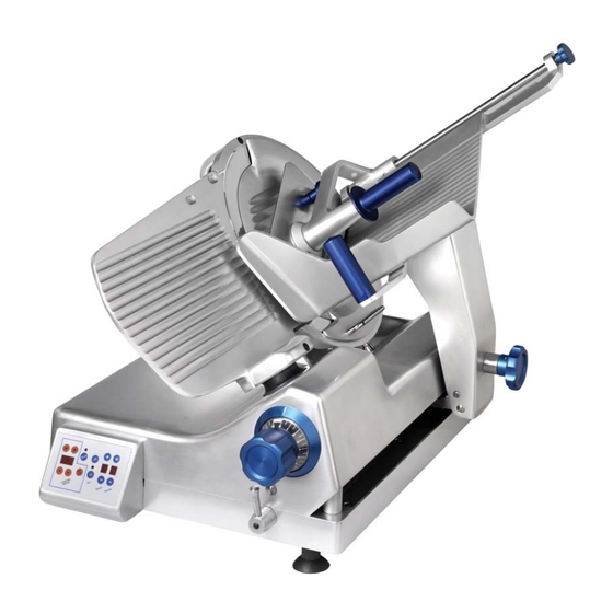
LIST OF ILLUSTRATIONS DESCRIPTION PAGE Figure 1 Overall View of Meat Slicer ......3 Figure 2 On/Off Switch . - Page 5 OVERALL VIEW OF MEAT SLICER FIGURE 1 1 Last Slice Device Shaft and Knob 8 Control Panel 2 Carriage 9 On/Off Switch (on left side -not shown) 3 Carriage Handle 10 Fence 4 Carriage Arm 11 Fence Cover Knob (not shown) 5 Carriage Arm Knob 12 Last Slice Device 6 Graduated Knob...
-
Page 6: Introduction
INSTALLATION INSTRUCTIONS INSPECTION All Univex slicers are inspected and tested at the factory; however, they should be inspected carefully by the person making the installation for loose, damaged or broken parts. Detached parts and fixtures should be checked against the packing list to determine all are present. Any damages, imperfections or shortages should be reported to the dealer or to Univex and the shipping carrier. -
Page 7: Controls Overview
(Figure 1 [3]). Do not hold or push the carriage from any other place. CONTROLS OVERVIEW This Univex slicer is designed to meet the cook’s demand for an efficient, sturdy slicer. This Univex slicer will give unfailing performance over a period of years, when operated and maintained according to the instructions contained in this manual. -
Page 8: Control Panel
CONTROL PANEL Counting Device: When using the slicer in the automatic mode, you can choose to use the slice counting device. To turn this feature on, press the on/off button (Figure 4 [2]). To set the desired number of slices to be cut, press the “+”... -
Page 9: Manual Mode Operating Instructions
MANUAL MODE OPERATING INSTRUCTIONS 1. With the slicer OFF, pull the carriage toward you until it stops at the full returned position and place the food product on the carriage. Slice only boneless, unfrozen product with this slicer. Use the last slice device (Figure 1 [12]) to hold the product in place during slicing. If the last slice device is not needed, it can be stored out of the way by swinging it back behind the carriage and locking it on the retaining pin. -
Page 10: Automatic Mode Operating Instructions
AUTOMATIC MODE OPERATING INSTRUCTIONS Warning: Before beginning to use the slicer in the automatic mode, make sure the operating mode switch (Figure 3 [2]) is in the neutral (center) position. Caution: Never put your hands or any body parts near the carriage when the slicer is operating. Keep your hands and arms away from all moving parts. - Page 11 AUTOMATIC MODE OPERATING INSTRUCTIONS CONTINUED Warning: Never attempt to adjust, load or unload the carriage while the slicer is in automatic operation! Warning: If the product needs to be adjusted during automatic slicing, always press the “set off” button (Figure 4 [4]). Turn the operating mode switch (Figure 3 [2]) to the neutral (center) position.
-
Page 12: Sharpening Instructions
SHARPENING INSTRUCTIONS This slicer is equipped with a knife having a concave or hollowed surface for superior slicing quality. Of course, any knife, however superior, must be sharpened regularly and properly in order to produce not only the highest quality slices, but also to allow it to maintain its productivity. The knife sharpener (Figure 13) on this machine is a fence mounted design. - Page 13 6. Turn the slicer ON. Rotate the sharpener wheel (Figure 7 [5]) downward to position “1” (Figure 7 [4]) and hold. This will start the grinding stone rotating. Run the slicer until the beveled cutting surface on the back side of the blade cleans up. This can take from 15 to 30 seconds depending on how dull the blade was allowed to become.
-
Page 14: Operator's Care Of The Slicer
OPERATORS CARE OF SLICER CLEANING 1. Warning: Never touch the knife edge. Always keep your hands, fingers and arms clear of the knife. 2. Warning: Turn the slicer OFF and disconnect the power supply cord. 3. Turn the slice adjustment knob (Figure 3 [1]) to the fully closed position (beyond “0”) so the knife edge is not exposed. -
Page 15: Lubricating Instructions
LUBRICATION AND FUNCTION CHECK Warning: Turn the slicer OFF and disconnect the power supply cord and close the fence all the way before lubricating. General lubrication should be performed in accordance with the lubrication instructions below. During this lubrication sequence, be sure to check for free operation and movement of related parts as well as for excessive wear and looseness of various parts. -
Page 16: Troubleshooting Guide
TROUBLESHOOTING GUIDE TROUBLE POSSIBLE CAUSE REMEDY 1. Slicer will not 1.1 Electrical service down. 1.1 Check electrical service. operate. Replace fuse or reset circuit breaker as necessary. 1.2 Knife guard knob not tight. 1.2 Tighten knob. 1.3 Circuit breaker tripped. 1.3 Reset circuit breaker. -
Page 17: Knife Removal
REPAIR INSTRUCTIONS (Including disassembly, replacement and reassembly) Warning: Always disconnect the electrical power supply cord before attempting repair. KNIFE (Removal) 1. Warning: Disconnect the electrical power supply cord. 2. Close the fence all the way, loosen the carriage arm knob and tilt the carriage to the cleaning position. -
Page 18: Slicer Base Removal
SLICER BASE REMOVAL 1. Warning: Disconnect the electrical power supply cord. 2. Place the operating mode switch in the manual position. 3. Remove the six pan head screws (Figure 18 [5]) and remove the bottom cover (Figure 18 [16]). 4. Remove the four rubber feet and remove the four socket head cap screws (Figure 18 [7]) and carefully remove the slicer base while guiding the belt out of the jaw assembly. -
Page 19: Carriage Drive Bearing Replacement
CARRIAGE DRIVE BEARING REPLACEMENT 1. Remove the slicer base assembly and the carriage drive motor belt per the above procedures. 2. Remove the belt guard (Figure 20 [21]). 3. Remove the eight socket head cap screws (Figure 20 [7]) and remove the two bearing blocks (Figure 20 [8 and 22]) and remove the two keys (Figure 20 [3]). -
Page 20: Knife Drive Belt Replacement
KNIFE DRIVE ASSEMBLY 1. Remove the knife per the knife removal instructions on page 15. 2. Remove the slicer base assembly per the slicer base removal instructions on page 16. 3. Loosen the belt tension by loosening the thumb screw (Figure 14 [7]) and bolt (Figure 14 [3]). 4. -
Page 21: Replacement Parts
KNIFE ASSEMBLY FIGURE 10 ITEM No. PART No. DESCRIPTION QTY. F4020084 Body, Slicer GL12 (manual) Body, Slicer (automatic) F303040 Foot, Rubber F406BA03 Spacer, Foot F7001758 Screw, Socket Head Set M8-1.25 x 35 F4101082 Screw, Deflector F700264F Washer, Bellville F405BC07 Deflector F7004006 Nut, M6 F7003806... - Page 22 KNIFE ASSEMBLY FIGURE 10 Page 20...
- Page 23 CARRIAGE SLIDE ASSEMBLY FIGURE 11 ITEM No. PART No. DESCRIPTION QTY. F4100872 Pivot, Front blocking bar F3030504 Washer, Rubber F3030502 Washer, Rubber F4070209 Bar, Carriage Slide F7003339 screw, Socket Head Cap M6-1.0 x 25 F4100800 Nut, Jam M12-1.75 F7003338 Screw, Socket Head Cap M6-1.0 x 16 F4070309 Bar, Carriage Slide F405FC08...
- Page 24 CARRIAGE SLIDE ASSEMBLY FIGURE 11 Page 22...
- Page 25 CARRIAGE ASSEMBLY FIGURE 12 ITEM No. PART No. DESCRIPTION QTY. F4020126 Carriage F4100780 Pad, Nylon F4020282 Plate, Last Slice Device F4090302 Knob (plastic) F4090361 Knob (plastic, black) F3040125 Plug F3030814 Bushing F4100776 Nut, Acorn M5-0.8 F70035 Screw, Socket Head Set M5-0.8 x 12 F4100776 Pin, Rubber F4100780...
- Page 26 CARRIAGE ASSEMBLY FIGURE 12 Page 24...
- Page 27 F4100791 Shaft, Slice Control F3030809 Bushing F405CB32 Gibb Bracket, Switch Front (1000s only) Switch (1000s only) Screw, Socket Head Cap M6-1.0 x 18 Bracket, Switch Rear (1000s only) Screw, Socket Head Cap M6-1.0 x 20 F700013A Screw, Socket Head Cap M6-1.0 x 30 F7001748 Screw, Slotted Set Brass M6-1.0 x 20...
- Page 28 SLICE THICKNESS CONTROL FIGURE 13 Page 26...
- Page 29 KNIFE DRIVE MOTOR FIGURE 14 ITEM No. PART No. DESCRIPTION QTY. F3030100 Belt, Poly-V F7000462 Nut, M6-1.0 Screw, Hex Head Cap M6-1.0 x 30 F405CB20 Bracket, Drive Belt Tensioner F7003337 Screw, Socket Head Cap M6-1.0 x 16 Nut, M8-1.25 F7000130 Screw, Thumb M8-1.25 x 45 F3010108 Motor, 115V, 60HZ, 1PH...
- Page 30 KNIFE DRIVE MOTOR FIGURE 14 Page 28...
- Page 31 KNIFE DRIVE ASSEMBLY FIGURE 15 ITEM No. PART No. DESCRIPTION QTY. F4101068 Bushing, Tapered F3030203 Seal F7000535 Retaining Ring F3030306 Bearing F4100153 Spacer, Bearing F4010349 Pulley, Driven F4101114 Shaft, knife F7001745 Screw, Socket Head Set M6-1.0 x 8 F700207K Washer, Shim as needed Page 29...
- Page 32 LIFT ASSEMBLY FIGURE 16 ITEM No. PART No. DESCRIPTION QTY. 9613111 Block, Pivot 1200488 Screw, Socket Head Cap 5/16-18 x 1 Stainless Steel 4400429 Pin, Roll 1/4 x 3/4 Stainless Steel 9613104 Wheel, Nylon 1200002 Screw, Hex Head Cap 1/4-20 x 1-1/4 Stainless Steel 9613110 Lever, Lift 1200319...
- Page 33 SHARPENER ASSEMBLY FIGURE 17 ITEM No. PART No. DESCRIPTION QTY. F2070501 Complete Sharpener Assembly F4101298 Cap, Selector Knob F7003339 Screw, Socket Head Cap M6-1.0 x 25 F4101301 Bushing, Selector Knob F3031200 Spring, Flat F7900021 Screw, Hone Shaft F4101297 Knob, Selector F4101302 Bearing, M12 x 13 F4020143...
- Page 34 SHARPENER ASSEMBLY FIGURE 17 25 26 Page 32...
- Page 35 SLICER BASE ASSEMBLY FIGURE 18 ITEM No. PART No. DESCRIPTION QTY. F4020706 Base F4020705 Housing, Keypad F3040157 Keypad F7003032 Screw, Socket Head Cap M5-0.8 x 12 F4101004 Handle, Mode Switch Plug F7003340 Screw, Socket Head Cap F4020612 Hub, Mode Switch F7003536 Screw, Socket Head Set E-Ring...
- Page 36 SLICER BASE ASSEMBLY FIGURE 18 Page 34...
- Page 37 JAW ASSEMBLY FIGURE 19 ITEM No. PART No. DESCRIPTION QTY. F4101254 Body, Jaw F4101255 F4101256 Arm, Switch Trip F7002426 Screw, Slotted Flat Head M4-0.7 x 10 Screw, Socket Head Set M5-0.8 x 6 F4101258 Pin, Switch Trip Arm F4101259 Link F3040162 Magnet F7003610...
- Page 38 JAW ASSEMBLY FIGURE 19 Page 36...
- Page 39 CARRIAGE DRIVE ASSEMBLY FIGURE 20 ITEM No. PART No. DESCRIPTION QTY. F3010137 Motor F405FC70 Angle, Motor Mounting Key, 8mm x 8mm x 20mm F3030131 Belt, Drive F4101260 Bushing, Taper Lock RCK61 F4101245 Pulley, Driven F7003348 Screw, Socket Head Cap M8-1.25 x 20 Block, Drive Bearing F7003613 Ring, Retaining...
- Page 40 CARRIAGE DRIVE ASSEMBLY FIGURE 20 Page 38...
- Page 41 WIRING DIAGRAM 115V, 60HZ, 1PH FIGURE 21 Page 39...
- Page 42 SERVO DRIVE AMPLIFIER DIAGRAM FIGURE 22 Page 40...
- Page 43 Warranty The Univex 1000S Slicer carries a one-year, on- site parts and labor warranty against any defects in materials or workmanship. The one-year period begins on the date of purchase by the end user and remains in full effect provided the unit is used properly and in accordance with our instructions.
Need help?
Do you have a question about the 1000S and is the answer not in the manual?
Questions and answers