Tennant 6400 Operator's Manual
Hide thumbs
Also See for 6400:
- Operator's manual (80 pages) ,
- Operator's manual (72 pages) ,
- Operator's manual (80 pages)

Subscribe to Our Youtube Channel
Related Manuals for Tennant 6400


Summary of Contents for Tennant 6400
- Page 1 6400 (Liquid Cooled) Sweeper Operator Manual North America / International MM429 Rev. 12 (04-2009) *MM429* www.tennantco.com Home Find... Go To..
- Page 2 Engine exhaust from this product contains chemicals known to the State of California to cause cancer, birth defects, or other reproductive harm. Thermo- -Sentry, Instant Access, and Perma- -Filter are US registered and unregistered trademarks of Tennant Company. Specifications and parts are subject to change without notice.
-
Page 3: Table Of Contents
....BRUSH DOOR SEALS ... 6400 MM429 (9- -04) Home Find... Go To.. - Page 4 INDEX ........6400 MM429 (9- -04) Home...
-
Page 5: Safety Precautions
- - Use cardboard to locate leaking hydraulic fluid under pressure. 2. Before starting machine: - - Use Tennant supplied or approved - - Check for fuel leaks. replacement parts. - - Keep sparks and open flame away from refueling area. - Page 6 380 mm (15 in) or less from the ground. - - Set parking brake after machine is loaded. - - Block machine tires. - - Tie machine down to truck or trailer. 6400 MM429 (9- -02) Home Find... Go To..
- Page 7 THE SIDES OF THE RADIATOR SHROUD. 350159 HOPPER SUPPORT LABEL - - LOCATED ON HOPPER LIFT ARMS LABEL - - LOCATED ON BOTH LIFT ARMS AND THE HOPPER BOTH LIFT ARMS. SUPPORT BAR. 6400 MM429 (12- -96) Home Find... Go To..
-
Page 8: Operation
Tennant representative. - Order parts and supplies directly from your authorized Tennant representative. Use the parts manual provided when ordering parts. - After the first 50 hours of operation, follow the recommended procedures stated in the MAINTENANCE CHART. -
Page 9: Machine Components
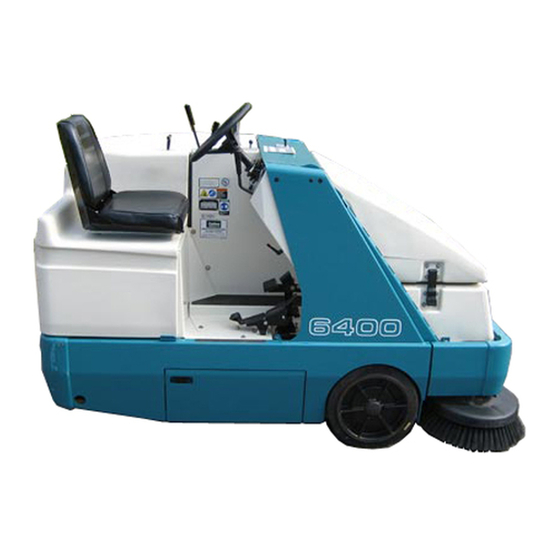
OPERATION MACHINE COMPONENTS 350159 A. Operator seat B. Steering wheel C. Instrument panel D. Hopper cover E. Side brush F. Hopper access door G. Brush door H. Seat support Fuel tank 6400 MM429 (8- -07) Home Find... Go To.. -
Page 10: Symbol Definitions
Hopper door close Main brush down and on Start Main brush up and off Horn Battery charging system Operating lights Engine oil pressure Hazard light Engine water temperature Side brush down and on 6400 MM429 (8- -07) Home Find... Go To.. -
Page 11: Home Find... Go To
OPERATION Side brush up and off Circuit breaker #3 Variable pressure Circuit breaker #4 Side brush pressure Circuit breaker #5 Circuit breaker #1 Unleaded fuel only Circuit breaker #2 6400 MM429 (4- -09) Home Find... Go To.. -
Page 12: Controls And Instruments
U. Steering wheel V. Hourmeter W. Steering wheel tilt handle X. Ignition switch Y. Horn button Z. Side brush lever AA.Operating light switch (Operating/hazard light switch option) BB.Side brush down pressure knob CC.Circuit breakers 6400 MM429 (8- -07) Home Find... Go To.. -
Page 13: Operation Of Controls
Reverse: Press the bottom of the directional pedal with the heel of your foot. 07791 Neutral: Take your foot off the directional pedal and it will return to the Neutral position. 07792 6400 MM429 (9- -96) Home Find... Go To.. -
Page 14: Brake Pedal
The seat support lever releases and locks the seat support. Release: Pull the lever back and lift the seat support. Lock: Close the seat support and release the lever to lock the support in place. 6400 MM429 (9- -96) Home Find... Go To.. -
Page 15: Throttle Lever
NOTE: If the machine is equipped with the hopper door closed light option, the light will come on when the hopper door is closed. 6400 MM429 (12- -96) Home Find... Go To.. -
Page 16: Main Brush Lever
Vacuum fan off position. It will also make the hopper temperature light come on. If this happens, stop the machine, eliminate the source of the heat, and return the lever to the Vacuum fan on position. 6400 MM429 (6- -99) Home Find... Go To.. -
Page 17: Charging System Light
The engine water temperature light comes on when the temperature of the engine coolant is more than 107_ C (225_ F). If the light comes on, stop operating the machine. Locate the problem and have it corrected. 6400 MM429 (9- -96) Home Find... Go To.. -
Page 18: Hopper Temperature Light - - Thermo Sentry
The LPG fuel level low light comes on when the LPG fuel tank is almost empty. The LPG fuel tank has 10 to 15 minutes of fuel remaining when the level light comes on. 6400 MM429 (8- -07) Home Find... Go To.. -
Page 19: Clogged Filter Light (Option)
The hopper door closed light comes on when the hopper door is closed. Make sure the hopper door is open all the way and the hopper door closed light is off, before sweeping. 6400 MM429 (6- -00) Home Find... Go To.. -
Page 20: Hydraulic Filter Bypass Light
ENGINE CHOKE KNOB The engine choke knob controls the engine choke on gasoline powered machines. On: For cold starting, pull the engine choke knob out. Off: Push the engine choke knob in. 6400 MM429 (9- -04) Home Find... Go To.. -
Page 21: Steering Wheel
FOR SAFETY: When starting machine, keep foot on brake and directional pedal in neutral. Start: Turn the key all the way clockwise. Release the key as soon as the engine starts. Stop: Turn the key counterclockwise. 6400 MM429 (9- -96) Home Find... Go To.. -
Page 22: Horn Button
Operating lights on: Press the top of the operating/hazard lights switch. Operating/Hazard lights on: Press the bottom of the operating/hazard lights switch. Off: Place operating/hazard lights switch in the middle position. 6400 MM429 (9- -96) Home Find... Go To.. -
Page 23: Side Brush Down Pressure Knob
Circuit Breaker Rating Circuit Protected CB-1 15 A Thermo Sentry CB-2 15 A Hourmeter, engine, fuel level CB-3 15 A Hopper, brushes CB-4 15 A Operating lights CB-5 15 A Horn 6400 MM429 (8- -07) Home Find... Go To.. -
Page 24: Operator Seat
07796 The seat front-to-rear position lever adjusts the seat position. Adjust: Pull the lever out, slide the seat backward or forward to the desired position and release the lever. 07797 6400 MM429 (9- -96) Home Find... Go To.. -
Page 25: Hopper Support Bar
DO NOT rely on the machine hydraulic system to keep the hopper raised. WARNING: Raised hopper may fall. Engage hopper support bar. 6400 MM429 (9- -96) Home Find... Go To.. -
Page 26: How The Machine Works
- Check the sweeping brush patterns for adjustment. - Check the brakes and steering for proper operation. - Check the fuel level - Check the service records to determine maintenance requirements. 6400 MM429 (9- -04) Home Find... Go To.. -
Page 27: Changing An Lpg Fuel Tank
NOTE: Make sure the LPG fuel tank matches the fuel system (liquid tank with liquid system). 7. Fasten the tank hold-down clamp to lock the tank in position. 350412 6400 MM429 (6- -01) Home Find... Go To.. -
Page 28: Home Find... Go To
350412 9. Open the tank service valve slowly and check for leaks. Close the service valve immediately if an LPG leak is found, and tell the appropriate personnel. 350412 6400 MM429 (9- -96) Home Find... Go To.. -
Page 29: Starting The Machine
3. Move the throttle lever back into the Idle engine speed position. 4. On gasoline powered machines, pull out the choke knob when the engine is cold. Push in the choke knob after the engine is running smoothly. 6400 MM429 (6- -99) Home Find... Go To.. -
Page 30: Home Find... Go To
Keep engine properly tuned. 7. Move the throttle lever forward into the Fast engine speed position. 8. Release the machine parking brake. 9. Drive the machine to the area to be cleaned. 6400 MM429 (9- -96) Home Find... Go To.. -
Page 31: Sweeping And Brush Information
Natural Fiber 8- double row main brush -- The natural choice for cleaning fine debris on carpet and sweeping very heavy dust and other fine particles on hard surfaces. 6400 MM429 (6- -01) Home Find... Go To.. -
Page 32: Sweeping
Hopper door open position to open the hopper door. NOTE: If the machine is equipped with the hopper door closed light option, the light will be off when the hopper door is open. 6400 MM429 (9- -96) Home Find... Go To.. -
Page 33: Home Find... Go To
Vacuum fan on position. 4. Lower and start the main brush with the main brush lever. 5. Lower and start the side brush with the side brush lever. 6. Sweep as needed. 6400 MM429 (9- -96) Home Find... Go To.. -
Page 34: Stop Sweeping
2. Raise and stop the main brush with the main brush lever. 3. Shake the dust filter by holding the vacuum and filter shaker lever in the Filter shaker position for 30 seconds. 6400 MM429 (9- -96) Home Find... Go To.. -
Page 35: Emptying The Hopper
5. Drive the machine up to the debris container. Position the hopper over the debris container. 6. Move the vacuum and filter shaker lever into the Vacuum fan off position. 6400 MM429 (12- -96) Home Find... Go To.. - Page 36 Hopper door open position to open the hopper door. NOTE: If the machine is equipped with the hopper door closed light option, the light will be off when the hopper door is open. 6400 MM429 (9- -96) Home Find... Go To..
-
Page 37: Stop The Machine
1. Stop sweeping. 2. Take your foot off the directional pedal. Step on the brake pedal. 3. Move the throttle lever back into the Idle engine speed position. 4. Set the machine parking brake. 6400 MM429 (9- -96) Home Find... Go To.. - Page 38 FOR SAFETY: Before leaving or servicing machine, stop on level surface, set parking brake, turn off machine, and remove key. 6. LPG powered machines: Close the LPG tank’s liquid service valve. 350412 6400 MM429 (9- -96) Home Find... Go To..
-
Page 39: Post-Operation Checklist
Clean as required. - Check the brakes and steering for proper operation. - Check the fuel level - Empty the debris hopper. - Check the service records to determine maintenance requirements. 6400 MM429 (9- -04) Home Find... Go To.. -
Page 40: Engaging Hopper Support Bar
FOR SAFETY: When using machine, make sure adequate clearance is available before raising hopper. NOTE: Be aware that the minimum ceiling height needed to high dump the hopper is 2340 mm (92 in). 6400 MM429 (9- -96) Home Find... Go To.. - Page 41 WARNING: Lift arm pinch point. Stay clear of hopper lift arms. 7. Move the throttle lever back into the Idle engine speed position. 8. Shut the engine off. 6400 MM429 (9- -96) Home Find... Go To..
-
Page 42: Disengaging Hopper Support Bar
3. Pull and hold the hopper lever back into the Hopper up position to raise the hopper slightly. 4. Put the support bar in its storage position. WARNING: Lift arm pinch point. Stay clear of hopper lift arms. 6400 MM429 (9- -96) Home Find... Go To.. -
Page 43: Operation On Inclines
The maximum rated incline is 8_ or 14.1% with a full hopper and 10_ or 17.6% with an empty hopper. FOR SAFETY: When using machine, go slowly on inclines and slippery surfaces. 6400 MM429 (9- -96) Home Find... Go To.. -
Page 44: Options
4. Connect the vacuum hose to the vacuum wand. 5. Remove the plug from the side of the hopper. 6. Connect the other end of the vacuum hose to the hopper hose connector. 7. Start the engine. 6400 MM429 (12- -96) Home Find... Go To.. - Page 45 14. Remove the vacuum hose from the hopper connection. 15. Replace the plug in the side of the hopper. 16. Disconnect the vacuum hose from the vacuum wand. 17. Put the vacuum wand and hose in the mounting clips. 6400 MM429 (12- -96) Home Find... Go To..
-
Page 46: Machine Troubleshooting
Empty hopper Hopper lip skirts worn or damaged Replace lip skirts Hopper door partially or Open hopper door completely closed Wrong sweeping brush Contact TENNANT representative for recommendations Recirculation flap damaged Replace flap 6400 MM429 (12- -96) Home Find... Go To.. - Page 47 OPERATION 6400 MM429 (9- -04) Home Find... Go To..
-
Page 48: Maintenance
Check for damage, wear and ad- justment Main brush Check for damage or wear Check brush pattern Side brush Check for damage or wear Check brush pattern Hopper dust filter Shake 50 Hours Main brush Rotate end-for-end 6400 MM429 (9- -04) Home Find... Go To.. - Page 49 HYDO Tennant or approved hydraulic fluid . . . Special lubricant, Lubriplate EMB grease (TENNANT part no. 01433--1) . . . Water and permanent-type ethylene glycol anti-freeze, --34_ C (--30_ F) NOTE: More frequent intervals may be required in extremely dusty conditions.
-
Page 50: Lubrication
The rear wheel support bearings must be lubricated every 200 hours of operation. Use Lubriplate EMB grease (Tennant part no. 01433--1). STEERING CYLINDER The steering cylinder has one grease fitting on the rear wheel support end of the cylinder. -
Page 51: Front Wheel Bearings
HOPPER LIFT ARM PIVOTS The hopper lift arms have two grease fittings, one on each lift arm. Lubricate with Lubriplate EMB grease (Tennant part number 01433--1) after every 200 hours of machine operation. 6400 MM429 (9- -96) Home Find... -
Page 52: Hydraulics
The quality and condition of the hydraulic fluid play a very important role in how well the machine operates. Tennant’s hydraulic fluid is specially selected to meet the needs of Tennant machines. 6400 MM429 (12- -96) Home Find... Go To.. -
Page 53: Hydraulic Hoses
MAINTENANCE Tennant’s hydraulic fluids provide a longer life for the hydraulic components. There are two fluids available for different temperature ranges: Tennant hydraulic fluid Part number Ambient temperature 65869 above 7_ C (45_ F) 65870 below 7_ C (45_ F) -
Page 54: Engine
The red line will return to a correct reading after the engine runs for a while. Reset the air filter indicator by pushing the reset button on the end of the indicator after replacing the air filter element. 6400 MM429 (6- -99) Home Find... Go To.. -
Page 55: Air Filter
To clean the air filter housing, remove the filter element. Carefully clean the end cap and the interior of the housing with a damp cloth. Clean the housing sealing surfaces. 6400 MM429 (6- -99) Home Find... Go To.. -
Page 56: Fuel Filter
The proper spark plug gap is 1 mm (0.043 in). VALVE CLEARANCE Check and adjust the intake and exhaust valve clearance to 0.145 to 0.185 mm (0.0057 to 0.0072 in) while the engine is cold after every 800 hours of operation. 6400 MM429 (6- -00) Home Find... Go To.. -
Page 57: Electrical
800 hours after that, clean and tighten the battery connections. Check the battery electrolyte level after every 100 hours of operation. FOR SAFETY: When servicing machine, avoid contact with battery acid. 6400 MM429 (6- -00) Home Find... Go To.. -
Page 58: Belts And Chains
A static drag chain prevents the buildup of static electricity in the machine. The chain is attached to the machine by a rear main brush skirt retaining bolt. Make sure the chain is touching the floor at all times. 6400 MM429 (12- -96) Home Find... Go To.. -
Page 59: Debris Hopper
The standard dust filter can also be rinsed, but the filter will degrade with each rinsing and should be replaced after rinsing five times. NOTE: Be sure the dust filter is completely dry before reinstalling it in the machine. 6400 MM429 (9- -02) Home Find... Go To.. -
Page 60: Removing Hopper Dust Filter
Put the cleaned or new dust filter in the hopper insert with the arrows pointing up. 6. Lower the hopper cover support and close the hopper cover. Latch the hopper cover. 6400 MM429 (9- -02) Home Find... Go To.. -
Page 61: Brushes
7. Slide the main brush onto the drive plug. Rotate the brush until it engages the drive plug, and push it all the way onto the plug. 8. Slide the main brush idler arm plug onto the main brush. 6400 MM429 (4- -09) Home Find... Go To.. -
Page 62: Checking And Adjusting Main Brush Pattern
5. Drive the machine off of the test area. 6. Observe the width of the brush pattern. The proper brush pattern width is 50 to 75 mm (2 to 3 in). 00582 6400 MM429 (9- -96) Home Find... Go To.. - Page 63 B. Move the brush shaft bearing bracket up or down in the slots. C. Check the main brush pattern and readjust as necessary. Then adjust the width of the main brush pattern. 6400 MM429 (9- -96) Home Find... Go To..
-
Page 64: Side Brush
6. Secure the pin by clipping the pin keeper over the end of the pin. 7. Adjust the side brush pattern with the side brush down pressure knob. 6400 MM429 (4- -09) Home Find... Go To.. -
Page 65: Side Brush Guard
Torque the front and rear compression springs to reduce excessive movement. The side brush tilt is adjusted with the side brush cable. Turn the clevis on the cable to get the desired side brush pattern. 6400 MM429 (9- -96) Home Find... Go To.. -
Page 66: Skirts And Seals
NOTE: The brush door skirts have slotted holes to allow for a ground clearance adjustment. Adjust the skirt height with the door closed. NOTE: Rear tire pressure will affect skirt clearances. 6400 MM429 (9- -96) Home Find... Go To.. -
Page 67: Rear Skirts
The hopper seals are located on the top and side portions of the machine frame that contact the hopper. Check the seals for wear or damage after every 100 hours of operation. 6400 MM429 (9- -97) Home Find... Go To.. -
Page 68: Hopper Access Door Seal
Check the seals for wear or damage after every 100 hours of operation. VACUUM FAN SEAL The vacuum fan seal is mounted on the vacuum shut-off plate. Check the seal for wear or damage after every 100 hours of operation. 6400 MM429 (9- -96) Home Find... Go To.. -
Page 69: Brakes And Tires
Torque the rear wheel nuts twice in the pattern shown to 122 to 155 Nm (90 to 110 ft lb) after the first 50 hours of operation, and every 800 hours of operation. 6400 MM429 (6- -01) Home Find... Go To.. -
Page 70: Pushing, Towing, And Transporting The Machine
Turn the bypass valve 90_ from the normal position before pushing or towing the machine. The illustration shows the bypass valve in the pushing or towing position. 6400 MM429 (6- -00) Home Find... Go To.. -
Page 71: Transporting The Machine
Do not drive the machine onto the truck or trailer unless the loading surface is horizontal AND is 380 mm (15 in) or less from the ground. 6400 MM429 (6- -00) Home Find... Go To.. - Page 72 Do not drive the machine off the truck or trailer unless the loading surface is horizontal AND 380 mm (15 in) or less from the ground. 6400 MM429 (6- -01) Home Find... Go To..
-
Page 73: Machine Jacking
Block machine up with jack stands. STORING MACHINE Before storing the machine for an extended time, the machine needs to be serviced to lessen the chance of rust, sludge, and other undesirable deposits from forming. 6400 MM429 (6- -01) Home Find... Go To.. -
Page 74: Specifications
Minimum turning radius, right 1490 mm (58.7 in) Minimum turning radius, left 1135 mm (44.7 in) Maximum rated incline with empty hopper 10_ / 17.6% Maximum rated incline with full hopper 8_ / 14.1% 6400 MM429 (6- -00) Home Find... Go To.. -
Page 75: Power Type
HYDRAULIC SYSTEM System Capacity Fluid Type Hydraulic reservoir 19.3 L (5.1 gal) TENNANT part no. 65869 -- above 7_ C (45_ F) TENNANT part no. 65870 -- below 7_ C (45_ F) Hydraulic total 20.8 L (5.5 gal) BRAKING SYSTEM Type... -
Page 76: Machine Dimensions
(48.4 in) 2260 mm (89 in) TOP VIEW 2085 mm (82 in) 1435 mm (56.5 in) 1135 mm 1135 mm (44.7 in) (44.7 in) SIDE VIEW FRONT VIEW 350158--- 350165 MACHINE DIMENSIONS 6400 MM429 (6- -00) Home Find... Go To.. -
Page 77: Index
Buttons, Horn, 20 Parking brake pedal, 12 Seat support release lever, 12 Bypass valve, 68 Side brush down pressure knob, 21 Side brush lever, 20 Steering wheel, 19 Steering wheel tilt handle, 19 6400 MM429 (9- -04) Home Find... Go To.. - Page 78 Lubrication, 48 Temperature, Light, 16 Oil capacity, 48 Thermo Sentry, 14, 16 Oil level, 24, 37 Vacuum fan seal, 66 Oil pressure, Light, 15 Spark plugs, 54 Specifications, 73 Valve clearance, 54 6400 MM429 (9- -04) Home Find... Go To..
- Page 79 Main brush down pressure knob, 14 Engine choke, 18 Main brush lever, 14 Main brush down pressure, 14 Side brush down pressure, 21 Maintenance, 46 Intervals, 46–48 Recommended, 6 Maintenance chart, 46–48 Motors, Propelling, 51 6400 MM429 (9- -04) Home Find... Go To..
- Page 80 Skirts and seals, 24, 37 Flushing system, 52 Spark plugs, 54 Hoses, 52 Rear skirts, 65 Rear wheel, 67 Steering cylinder, 48 Support, 48 Rear wheel support, 48 Bearings, 48 Grease fitting, 48 6400 MM429 (9- -04) Home Find... Go To..
- Page 81 Thermo Sentry, 14, 16 Throttle lever, 13 Tie down location, 70 Tires, 67 Rear wheel, 67 Specifications, 73 Towing machine, 68 Transporting machine, 68 Transporting the machine, 69 Travel speed, 72 Troubleshooting, 44 6400 MM429 (9- -04) Home Find... Go To..
- Page 82 INDEX 6400 MM429 (9- -04) Home Find... Go To..
Need help?
Do you have a question about the 6400 and is the answer not in the manual?
Questions and answers