Page 1
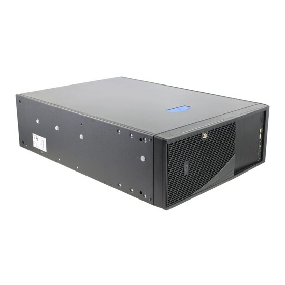
Intel® Server System P4000CP Family Quick Installation User's Guide Thank you for buying an Intel® Server System. The following information will help you assemble your Intel ® Server System and install components. If you are not familiar with ESD [Electrostatic Discharge] procedures used during system integration, see the complete ESD procedures described in your Service Guide.
System Overview Intel® Server System P4308CP4MHEN System Features and Components 550-W Fixed Power Supply I/O Ports Alternate RMM4 Knockout PCI Add-in Board Slot Covers AC Input Power Connector Serial Port Knockout A Kensington* Cable Lock Mounting Hole Padlock Loop Alternate RMM4 Knockout Front Control Panel 5.25"...
Page 6
System Overview Intel® Server System P4208CP4MHGC System Features and Components 750-W Hot Swap Power Supply (Two) AC Input Power Connector (Two) I/O Ports Alternate RMM4 Knockout PCI Add-in Board Slot Covers Alternate Serial Port Knockout A Kensington* Cable Lock Mounting Hole...
General Installation Process The installation instructions in this section are for general components of Intel® Server System P4000MCP family, but the illustrations are based on the Intel® Server System P4308CP4MHEN. Minimum Hardware Requirements Preparing the System To avoid integration difficulties and possible damage to your system, make sure you have components from each category below.
General Installation Process Install the Processor(s) ... continued CAUTION: When unpacking a processor, hold by the C. Install the Processor B. Open the Load Plate edges only to avoid touching the gold contact pins. Take the processor out of the Press the locking lever slightly to raise the box and remove the Orient the processor with the socket so...
Memory Type: Minimum of one 1 GB, DDR3 800/1066/1333 MHz ECC UDIMM/RDIMM/LRDIMM. DDR3 Other Memory sizing and configuration is supported only for qualified DIMMs approved by Intel. For a list of Memory supported memory, see the tested memory list at http://serverconfigurator.intel.com/default.aspx...
General Installation Process Install Hard Drive 2.5" Hot-Swap Hard Drive Carrier (For system with 2.5" hot-swap hard drive bay only) Remove the four screws securing the Install the hard disk drive using the plastic retention device to the 2.5" four screws as shown. Make Sure the HDD carrier.
General Installation Process Install PCI-e Card Assembly Remove the PCI-e slot shield by pushing the Rotate the PCI-e shield out from inside the chassis. retainer all the way to open. Install the optional PCI-e card fixture with screws. The card fixture helps to hold heavy PCI-e cards (i.e GPGPU S e r v e card).
Caution: Carefully remove the knock out with screwdriver, directly removing it with finger has potential risk. ® Connect the cable to the cable connector on the Intel Dedicated Server Management NIC module. Mount the NIC module to the rear panel of the chassis and secure the bracket with two screws.
General Installation Process Install Intel® RAID Smart Battery (optional) Align the tabs on the plastic battery holder with the mounting holes in the chassis and slide the plastic battery holder toward the front of the chassis until the tabs engage with the mounting holes.
BIOS version. Compare this to the versions at: your keyboard, mouse, http://www.intel.com/support video, and other I/O cables. If new versions are available, update the BIOS on your server. See the User Guide on the Intel Server Deployment and ® Connect the AC Management DVD for update instructions.
Reference HDD Cage Cable Connection Note: Refer to the documents which come with your server board and/or RAID controller card for instructions on connecting backplane cables to your server board or RAID controller card. 4 x 3.5" HDD Cage 8 x 3.5" HDD Cage Connect the I C cable to I C_IN connector on backplane.
Reference Front Panel Controls and Indicators D E F G H Reservation(Optional VGA/Serial Port) NMI Button System Status LED USB Connectors NIC LED System Power Button with Power LED ID Button with ID LED Integrated System Reset Button HDD Activity LED Cable Routing Diagram Figure 1 Figure 2...
Need help?
Do you have a question about the P4308CP4MHEN and is the answer not in the manual?
Questions and answers