Table of Contents
Advertisement
Quick Links
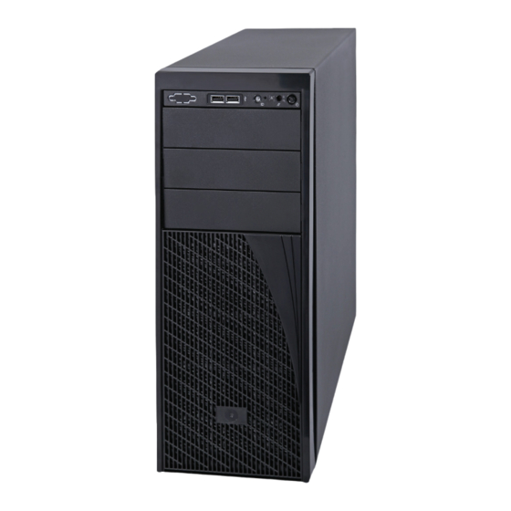
Intel® Server System P4000RP Family
Quick Installation User's Guide
Thank you for buying an Intel® Server System. The following information will help you
assemble your Intel ® Server System and install components.
If you are not familiar with ESD [Electrostatic Discharge] procedures used during
system integration, see the complete ESD procedures described in your Service Guide.
This guide and other supporting documents are located on the web at:
http://www.intel.com/p/en_US/support.
G85600-002
Advertisement
Table of Contents

Related Manuals for Intel P4000RP


Summary of Contents for Intel P4000RP
- Page 1 Intel® Server System P4000RP Family Quick Installation User's Guide Thank you for buying an Intel® Server System. The following information will help you assemble your Intel ® Server System and install components. If you are not familiar with ESD [Electrostatic Discharge] procedures used during system integration, see the complete ESD procedures described in your Service Guide.
- Page 2 (This page is intentionally left blank.)
-
Page 3: Table Of Contents
Install Tool-less CD-ROM or DVD-ROM Drive ............6 Install Hard Drive ......................... 6 Install PCI-e Card Assembly ................... 7 Install Intel® Remote Management Module 4 NIC (optional) ....... 7 Install RMM4 EMI Cover (optional) ................8 Install Alternate Serial Port (optional) ..............8 Install Intel®... - Page 4 Intel is a registered trademark of Intel Corporation or its subsidiaries in the United States and other countries. *Other names and brands may be claimed as ® the property of others. Copyright © 2013, Intel Corporation. All rights reserved.
-
Page 5: System Overview
System Overview Intel® Server System P4308RPLSHDR System Features and Components 460W Hot Swap Power Supply (Two) AC Input Power Connector (Two) I/O Ports RMM4 Knockout PCI Add-in Board Slot Covers Alternate Serial Port Knockout A Kensington* Cable Lock Mounting Hole... - Page 6 System Overview Hot Swap Hard Drive Bay Options and HDD Numbering 8 x 3.5" Hot-Swap Drive Cage...
-
Page 7: General Installation Process
General Installation Process The installation instructions in this section are for general components of Intel® Server System P4000RP family. Minimum Hardware Requirements Preparing the System To avoid integration difficulties and possible damage to your system, Observe normal ESD (Electrostatic Discharge) procedures. -
Page 8: Install Active Heat Sink
General Installation Process Install the Processor ... continued E. Close the Load Plate D. Install the Processor Carefully lower the load plate Carefully lower the load plate CAUTION: The underside of the processor has components over the processor. over the processor. that may damage the socket wires if installed improperly. -
Page 9: Install Dimm Memory Modules
Note: For additional memory configurations, see the Service Guide on the Intel Server Deployment & Management DVD that accompanied ® your Intel Server System, or go to: ® http://www.intel.com/p/en_US/support/ (post-production) Memory sizing and configuration is supported only for qualified DIMMs approved by Intel . -
Page 10: Install Tool-Less Cd-Rom Or Dvd-Rom Drive
General Installation Process Install Tool-less CD-ROM or DVD-ROM Drive Finger Holes Insert the drive/slide assembly Press the release latch and use Get the slides from the Attach slides to the DVD or CD-ROM drive into the device bay until the the finger holes to Pull out the chassis side. -
Page 11: Install Pci-E Card Assembly
CAUTION: Carefully remove the knock out with screwdriver, directly removing it with finger has potential risk. ® Connect the cable to the cable connector on the Intel Dedicated Server Management NIC module. Mount the NIC module to the rear panel of the chassis and secure the bracket with two screws. -
Page 12: Install Rmm4 Emi Cover (Optional)
CAUTION: Care should be used when attaching or removing this cable. Mishandling the cable could cause damage. Install Intel® RAID Smart Battery (optional) Align the tabs on the plastic battery holder with the mounting holes in the chassis and slide the plastic battery holder toward the front of the chassis until the tabs engage with the mounting holes. -
Page 13: Install Intel® Raid Smart Battery (Optional)
Install Side Cover Finishing Up Slide the chassis cover on the chassis. Secure the chassis cover with the screws . ® See your Intel Server Board Quick Start Power User's Guide to connect CAUTION: This chassis must be operated with the your keyboard, mouse, SIDE COVERS installed to ensure proper cooling. -
Page 14: Install Software
A. Confirm BIOS Version: Look on the Server/System Management screen in the BIOS Setup Utility to determine the installed BIOS version. Compare this to the versions at: http://www.intel.com/support If new versions are available, update the BIOS on your server. See the User Guide on the Intel Server Deployment and Management DVD for update instructions. -
Page 15: Reference
Reference HDD Cage Cable Connection NOTE: Refer to the documents which come with your server board and/or RAID controller card for instructions on connecting backplane cables to your server board or RAID controller card. 8 x 3.5" HDD Cage Connect the I C cable to I C connector on backplane. -
Page 16: Front Panel Controls And Indicators
Main Power CPU Power SYS_FAN_4 Server Board SYS_FAN_1 SAS SPGIO HSBP_I SATA Front Panel Intel Server System P4304FP2SFCN ® Description CPU Power Cable Server Board Main Power Cable Backplane Power Cable ODD Power Cable Front Panel Cable and USB Cable... - Page 18 G85600-002...
Need help?
Do you have a question about the P4000RP and is the answer not in the manual?
Questions and answers