LG LW9228 Series Owner's Manual
Network dome camera
Hide thumbs
Also See for LW9228 Series:
- Owner's manual (66 pages) ,
- Owner's manual (60 pages) ,
- Owner's manual (67 pages)
Table of Contents

Subscribe to Our Youtube Channel
Related Manuals for LG LW9228 Series


Summary of Contents for LG LW9228 Series
- Page 1 OWNER’S MANUAL Network Dome Camera Please read this manual carefully before operating your set and retain it for future reference. MODELS LW9228 Series LW9228I Series LW9226 Series LW9226I Series P/NO : MFL67122201 1104 (V1.5)
-
Page 2: Safety Information
Safety Information Safety Information REGULATORY INFORMATION: FCC Part 15 CAUTION This equipment has been tested and found to comply with the limits for a Class A digital device, pursuant to Part 15 of the FCC Rules. These limits are designed to provide RISK OF ELECTRIC SHOCK reasonable protection against harmful interference when DO NOT OPEN... - Page 3 Safety Information Warning: Do not install this equipment in a confined space LG Electronics hereby declares that this/ such as a bookcase or similar unit. these product(s) is/are in compliance Warning: Wiring methods shall be in accordance with the with the essential requirements and other National Electric Code, ANSI/NFPA 70.
-
Page 4: Important Safety Instructions
Safety Information IMPORTANT SAFETY 14. Refer all servicing to qualified service personnel. Servicing is required when the apparatus has been INSTRUCTIONS damaged in any way, such as power-supply cord or plug is damaged, liquid has been spilled or objects have fallen into the apparatus, the apparatus has been exposed to rain or moisture, does not operate normally, or has been dropped. -
Page 5: About Static Electricity Removal
Safety Information About Static Electricity Removal • Before operating, please check proper temperature, humidity and power source ratings. Before installing the camera, touch a metal case or other Use the camera under conditions where temperature metallic parts with your hand to remove static electricity is from -10 °C to 50 °C and humidity is below 80 %. -
Page 6: Table Of Contents
Safety Precautions Operation and settings Preparation Before using the system Introduction Recommended PC Requirements Features Accessing the LG IP device Accessories LG Smart Web Viewer Overview Part Names and Functions Configuring the LG IP camera Accessing the Configuration menu System settings Installation Audio &... - Page 7 Contents General operation Camera menu settings Appendix Focus setting Exposure settings Specifications White Balance setting Day/Night setting 3D-DNR setting Color setting Sharpness setting PAN/TILT Settings Privacy Mask setting Special setting OSD Settings User title setting ZOOM MAG setting FUNCTION setting DOME ID setting LANGUAGE Setting RESET Setting...
-
Page 8: Preparation
A routine of manual operations can be stored and reproduced repeatedly. The Pan, Tilt and Zoom controls are available for pattern recording. The LG Network Camera is designed to use on an Ethernet network and must be assigned an IP address to make it NOTE accessible. -
Page 9: Accessories
• Day & Night Function For LW9226/LW9228 series This camera can be selected Color or Black & White. You can set Color in the daytime and Black & White at night due to the low illumination. -
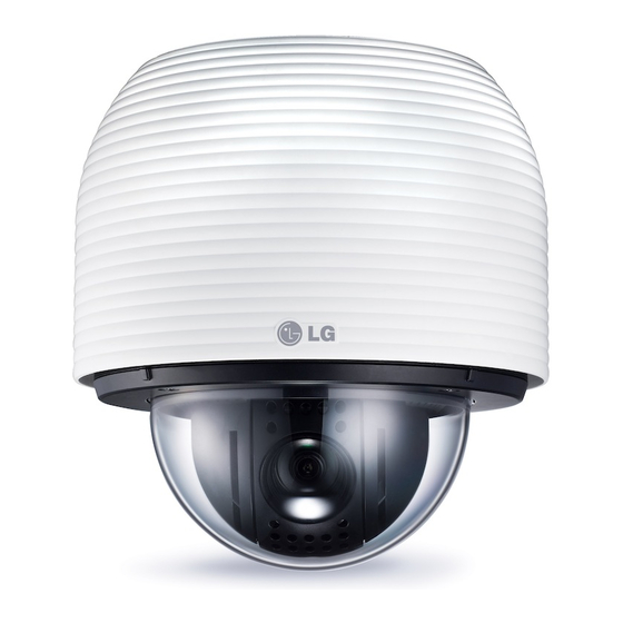
Page 10: Part Names And Functions
Preparation Part Names and Functions BNC connector cover cap Video output BNC connector LW9228I/LW9226I series for Indoor Supplies analog video signal (composite) to the connected device. Data Port A (RJ-45) Input data port for alarm (relay) signal. RS-485 data communication is not available. Data Port B (RJ-45) Output data port for alarm (relay) signal. - Page 11 Preparation LW9228/LW9226 series for Outdoor BNC connector cover cap Video output BNC connector Supplies analog video signal (composite) to the connected device. Data Port A (RJ-45) Input data port for alarm (relay) signal. RS-485 data communication is not available. Data Port B (RJ-45) Output data port for alarm (relay) signal.
-
Page 12: Installation
Installation Installation Connections Precautions • The following steps of installation and connection work should be done by qualified service personnel or system installers and should conform to all local codes. • Before you install and connect the camera, check and prepare the required peripheral devices and cables. •... -
Page 13: Connecting Display Device
Installation Connecting Display device CAUTION The video signal connection between the camera and the monitor. Do not connect one alarm sensor to the several camera’s alarm input connector. Display device connection Alarm input connection Alarm device Alarm device Alarm device Alarm device Alarm device Alarm device... -
Page 14: Alarm Output Connections
Installation ALARM output connections PORT A of the LW9228I/9226I series Description Color Connect the alarm device to the alarm output data port. Alarm signal output at an event occurrence. You can set the RS-485 + Red/White Alarm Output to the normal open or normal close mode. 1. -
Page 15: Connecting Network
Installation Connecting Network ALARM OUT [NC2] Blue You can control and monitor the system via network. Brown With the remote control (monitoring), you can change the system configuration or monitor the image via net- work. After the installation, check the network settings PORT B of the LW9228I/9226I series for the remote control and monitoring work. -
Page 16: Connecting Power Source
Installation Connecting power source Connecting Microphone and Speaker Device Connect a AC 24 V power source to the power input terminal as shown below. Optionally connect an active speaker and/or external microphone with a built-in amplifier. NOTE Keep the microphone away from the speaker to avoid howling. -
Page 17: Mounting The Camera
Installation Mounting the camera Surface mount (optional) Follow the instructions below to surface mount the camera. You can mount the camera on the ceiling or wall. CAUTION The building structure must be able to support 8 kg. Removing the Protection Tape 1. - Page 18 Installation 2. Install the surface mounting bracket on the ceiling. 4. Tighten the locking screw. 5. Connect the cables to the cable jacks of the camera body. After installing the camera, you should arrange the cables using the outlet box to protect the cables. 3.
-
Page 19: Ceiling Mount (Optional)
Installation Ceiling mount (optional) 3. Install the ceiling mounting bracket on the ceiling. Face the front of the ceiling mounting bracket toward the Follow the instructions below to mount the camera on the area of interest. ceiling. CAUTION The building structure must be able to support 8 kg. 1. - Page 20 Installation 5. Pass the connection cable through the inner side of 7. Tighten the locking screw. the ceiling. Connect the cables to the cable jacks of the camera body. 8. Connect the cables to the cable jacks of the camera body.
-
Page 21: Wall Mount (Optional)
Installation Wall mount (optional) 3. Connect the safety cable to the wall mount assembly. Install the camera by the following order. 1. Disassemble the PIPE Installation Bracket to remove the [A] part. Red Stripe 2. Install the PIPE Installation Bracket to the Wall Mount assembly. - Page 22 Installation 4. Drill a hole on the wall where you want to install the 7. Attach the camera to the camera assembly bracket by pipe. Pass the connection cable through the wall following step a and b. Align the locking point of mount assembly so that they hang down.
-
Page 23: Pendant Mount (Optional)
2. Install the PIPE Installation Bracket to the Pendant Mount assembly. NOTE You can install the PIPE Installation Bracket direct to the other type LG Wall Mount assembly. This LG Wall Mount assembly make to easy to install your camera. - Page 24 Installation 3. Connect the safety cable to the pendant mount 4. Drill a hole on the wall where you want to install the assembly. pipe. Pass the connection cable through the pendant mount assembly so that they hang down. Red Stripe...
- Page 25 Installation 5. Install the pendant mount assembly. 7. Attach the camera to the camera assembly bracket by following step a and b. Align the locking point of the wall mount assembly and the camera. 6. Connect the connection cable and the safety cable to the camera body.
- Page 26 Installation 9. Assemble the camera cover as shown below. NOTE You can install the PIPE Installation Bracket direct to the other type LG Wall Mount assembly. This LG Wall Mount assembly make to easy to install your camera.
-
Page 27: Operation And Settings
Requirements • Before using the LG IP device make sure the connections are correct and verify whether proper The LG IP device can be used with most standard operating power supply is used. systems and browsers. • Check the connections of the LG IP device for the correct conditions. -
Page 28: Accessing The Lg Ip Device
“admin”.) Click the [OK] button and then the LG Smart Web Viewer is displayed in your You can access the LG IP device by following the below browser. steps. Notes: •... -
Page 29: Lg Smart Web Viewer Overview
Operation and settings LG Smart Web Viewer Click to save the current image in JPEG format on your Overview computer. 1. Click the [Snapshot] button and then the Snapshot window is displayed. 2. Click the [Save] button in the Snapshot window. -
Page 30: Configuring The Lg Ip Camera
Note: If you want to exit the Configuration menu, select one The features and options of the LG IP camera are config- of the video stream in the Live ured through the Configuration menu. view drop-down list. - Page 31 Operation and settings Date & Time Maintenance Time zone System reboot Set the time difference from GMT in the area where the IP Click the [Reboot] button to restart the IP device. It takes device is installed. some minutes for the IP device to start again. Select the time zone in the area where the IP device is Restore and backup installed from the drop down list.
-
Page 32: Audio & Video Settings
Operation and settings Firmware Language list Select a language for the LG Smart Web Viewer › Upgrade configuration menu and information display. 1. Click the [Browse] button. • Save: Click this button to confirm the settings. 2. Find and open the firmware file. - Page 33 Operation and settings Stream › Bit rate: If the [Quality] option set to CBR, this option is displayed. Edit the bit rate value from 256 kbps to 10 240 kbps. • Save: Click this button to confirm the settings. Audio Master/Slave ›...
- Page 34 › Pan speed: Enter the panning speed of the PTZ 4. Click the [Save] button to confirm the settings. device in the edit box. Default value for the LG Pattern Multix Protocol is 60 and ranges from 0 to 127.
-
Page 35: Motion Detect
Operation and settings Preset tour Auto pan A preset tour is composed of a group of preset positions You can play the camera with auto pan function. that the operator can link together in a sequence. » To set the Auto Pan position 1. -
Page 36: Network Settings
Operation and settings » How to set the motion detect window NOTE 1. Click the [Add] button. The motion detect window is displayed. You can add the five windows maxi- The RTSP port number should not be same with mum for motion detection area. the web port number. - Page 37 DDNS Each stream using multicast needs its own a This free service is very useful when combined with the LG pair of multicast IP address and port numbers to DDNS Server. It allows the user to connect the IP device avoid address conflict.
-
Page 38: User Settings
Operation and settings User settings Basic The IP device is shipped with the login rights of administrator only. If others need to access the IP device excluding the configuration a login with viewer rights need to be created. A maximum of 50 users can be created. IP list ›... -
Page 39: Event Settings
Operation and settings Custom user: The user can login and Maximum view the live stream image only when Frame Video Codec Resolution Quality the “Enable anonymous login” option is Rate stream checked to enable it. H.264 HIGHEST Up to 5 NOTE H.264 MEDIUM... - Page 40 Operation and settings Event schedule list Event Server Event Servers are used to receive the recorded video clip » To edit the Event Schedule and/or notification messages. 1. Select the Trigger event and click the [Edit] button. Event schedule window is displayed. 2.
- Page 41 Operation and settings SMTP server list Sensor & Relay By selecting the e-mail option, a still image of the event is captured and an e-mail with the attached image file is sent to the specified mail address. » To add the SMTP server 1.
-
Page 42: Auto Tracking
Operation and settings Auto Tracking • The Auto Tracking is disabled temporary while the camera is moving based on some configurations: PRESET TOUR, GROUP TOUR, PATTERN TOUR, and AUTO PAN. • When NIGHT MODE or the camera height value is configured to 2.5M, ZOOM function will be inactivated Normal Scenario for Auto Tracking to operate Auto Tracking correctly. -
Page 43: Osd Menu Setup
1st level 2nd level 3rd level Contents AUTO/MANUAL/ONE PUSH/ FOCUS MODE ZOOM TRIG FOCUS LW9228 series: 50 CM, 1.8 M, 3 M, 6 M FOCUS DIST LW9226 series: 50 CM, 1 M, 3 M, 5 M RETURN IRIS AUTO/MANUAL OFF/LOW/MIDDLE/HIGH WDR/BLC... - Page 44 Operation and settings 3D-DNR MIDDLE HIGH COLOR -20 to 20 COLOR SHARPNESS 0 to 68 RETURN PAN/TILT SET MASK NUMBER 1 to 8 SET MASK MASK STATE ON/OFF PRIVACY MASK MASK COLOR GRAY, WHITE, BLACK WIDTH 2 to 320 HEIGHT 3 to 240 RETURN PROPORTIONAL PT...
- Page 45 Operation and settings The option depends LANGUAGE on the model. INFORMATION INITIALIZATION RESET FACTORY RESET RETURN RETURN...
-
Page 46: General Operation
Operation and settings General operation Camera menu settings Focus setting 1. Click the [OSD control] button on the LG Smart Web The camera adjusts the focus automatically by sensing the Viewer. center of the picture. 2. Click button. The camera setting menu appears on the live view window. -
Page 47: Exposure Settings
Operation and settings Focus Distance setting WDR/BLC setting Selects the minimum shooting distance for the focus. Use WDR/BLC option to set the options for BLC or WDR Select [FOCUS DIST] option on the [FOCUS] menu, then camera. select a focus distance value. 1. -
Page 48: White Balance Setting
Operation and settings SHUTTER (Shutter Speed) setting When the scene mostly contains high color temperature objects, such as a blue sky or Select the desired shutter speed for camera exposure. You can change the shutter speed to higher speed to capture sunset. -
Page 49: 3D-Dnr Setting
Operation and settings Color setting D/N LEVEL: Use button to select a level. DWELL TIME: Use button to select a You can switch the displayed picture to grayscale or color. dwell time. NOTE If you set the AGC to [OFF] or the SHUTTER is set to one of the SHUTTER options except AUTO on the [EXPOSURE] menu, the AUTO mode of the DAY/NIGHT function is not available and [---] mark is displayed. -
Page 50: Pan/Tilt Settings
Operation and settings PAN/TILT Settings 7. Use button to select the color of the mask zone box on the [MASK COLOR] option. 8. Select the [WIDTH] option and use button to adjust the horizontal size of the mask zone box. 9. -
Page 51: Auto Return
Operation and settings Compass Auto return You can display the north, south, east and west information This function can be used to specify automatic return to a on the screen. particular mode if a certain amount of time elapses without any operation being performed. -
Page 52: Osd Settings
Operation and settings OSD Settings • CLR: If you enter the wrong code, select [CLR] then press . All letters will be erased at once. • POS: Move the USER TITLE position on the screen using the buttons. • END: Select this option to exit the settings. ZOOM MAG setting Displays or removes the zoom OSD on the screen. -
Page 53: Language Setting
Operation and settings LANGUAGE Setting Information You can view the current camera information such as PTZ software version, camera software version, camera ID, Protocol and Baud Rate. Select a language for the setup menu and OSD display. 1. Select [INFORMATION] option on the [RESET] menu. 2. -
Page 54: Troubleshooting
• IP Conflicts: If the LG network device is set with a static IP address and if the DHCP option is set then there may be IP’s same as the network device and other network partner. - Page 55 If the video streaming does not start on the Web • The client computer that is interacting with the camera browser, install the LG Web Client ActiveX program on needs to have a sound card that is functional to your computer following the instructions on the Web support speaker and microphone.
-
Page 56: Open Source Software Notice
Glibc, libelf, libesmtp, live.media • libpcre : Copyright © 1997-2009 University of Cambridge LG Electronics offers to provide source code to you on • libxml2 : Copyright © 1998-2003 Daniel Veillard. CD-ROM for a charge covering the cost of performing •... - Page 57 Reference › Copyright 1992-1994 Jutta Degener, Carsten Bormann • Zlib : Copyright © 1995-2002 Jean-loup Gailly and Mark Adler. All rights reserved. Permission is hereby granted, free of charge, to any person obtaining a copy of this software and associated documentation files (the “Software”), to deal in the Software without restriction, including without limitation the rights to use, copy, modify, merge, publish, distribute, sublicense,...
- Page 58 Appendix Appendix Specifications Model LW9226 LW9226I LW9228 LW9228I Camera Image Sensor 4.5 mm EX-view HAD CCD x27 Zoom x37 Zoom Lens (F1.5 (Wide End), F3.8 (Tele End)) (F1.5(Wide End), F4.1(Tele End)) ( f = 3.25 mm to 88 mm ) ( f = 3.5 mm to 129 mm ) Resolution Up to 704 x 480, 704 x 576 (N/P)
- Page 59 Alarm In/Out Network Ethernet 10/100 Ethernet Security Password Protection, HTTPS(SSL, TLS) Protocol TCP/IP(IPv4), HTTP, HTTPS, RTP, RTSP, UDP, DHCP, FTP, SMTP, NTP, ARP, ICMP, DDNS(LG) Remote S/W LSS464 and Web Client Connections Up to 10 Misc. Protection IP66, Vandal Proof...
- Page 60 BZ03...
Need help?
Do you have a question about the LW9228 Series and is the answer not in the manual?
Questions and answers