Sign In
Upload
Download
Table of Contents
Contents
Add to my manuals
Delete from my manuals
Share
URL of this page:
HTML Link:
Bookmark this page
Add
Manual will be automatically added to "My Manuals"
Print this page
×
Bookmark added
×
Added to my manuals
Manuals
Brands
Varimixer Manuals
Mixer
V30
Operation manual
Varimixer V30 Operation Manual
Hide thumbs
1
2
3
Table Of Contents
4
5
6
7
8
9
10
11
12
13
14
15
16
17
18
19
20
21
22
23
24
25
26
27
28
29
30
31
32
page
of
32
Go
/
32
Contents
Table of Contents
Bookmarks
Table of Contents
Limited Warranty
Table of Contents
INSTALLATION Instructions
Construction of the Mixer
T He Maximum Capacity of the Mixer
Ecommended Maximum Speeds
Ecommended Maximum Speeds for Attachment Hub
E Rror Codes
O Peration of the Mixer
Start - up after Stop at High Speed
O Verload
C Orrect Use of TOOLS
Cleaning
AINTENANCE and Lubrication
Rease Types
OSSIBLE Solution
A Djustment of Special V - BELT
A Djustment of Speed
A Djustment of Bowl Fixing
A Djustment of Bowl Centering
A Djustment of Bowl Height
Ixer S Pare P Arts
Achine Column
B Owl a Rms
Lanetary Ead
T Ransmission
S Peed L Ever Assemply
Rive
Earbox
B Owl S Creen
Attachments a Nd O Ptional P Roducts
Advertisement
Quick Links
1
E Rror Codes
2
O Peration of the Mixer
3
Ixer S Pare P Arts
Download this manual
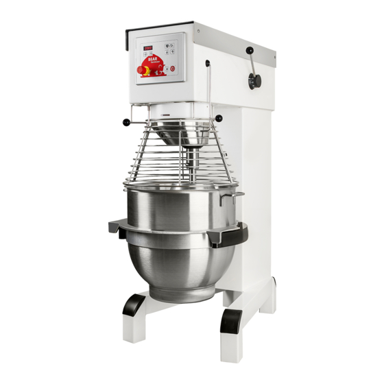
SPARE PART AND OPERATION MANUAL
FOOD MIXER
Models V30, V40, and V60
012016
1
Table of
Contents
Previous
Page
Next
Page
1
2
3
4
5
Advertisement
Table of Contents
Need help?
Do you have a question about the V30 and is the answer not in the manual?
Ask a question
Questions and answers
Related Manuals for Varimixer V30
Mixer Varimixer V20 Operation Manual
(32 pages)
Mixer Varimixer V40 Operation Manual
(32 pages)
Mixer Varimixer V60 Operation Manual
(32 pages)
Mixer Varimixer V5A TEDDY Spare Part And Operation Manual
(9 pages)
Mixer Varimixer ERGO100 Operating Instructions Manual
(24 pages)
Mixer Varimixer V30K Spare Part And Operation Manual
(32 pages)
Mixer Varimixer V30K Spare Part And Operation Manual
(32 pages)
Mixer Varimixer V20K Spare Part And Operation Manual
Food mixer (36 pages)
Mixer Varimixer KODIAK V20K Operating Instructions And Spare Parts
(32 pages)
Mixer Varimixer KODIAK V20KT Operating Instructions And Spare Parts Lists
(32 pages)
Mixer Varimixer V80 Spare Part And Operation Manual
(40 pages)
Mixer Varimixer V80 Operating Instructions Manual
(44 pages)
Mixer Varimixer V150PL Spare Part And Operation Manual
(36 pages)
Mixer Varimixer V150PLM Operating Instructions Manual
(36 pages)
Mixer Varimixer W20A Spare Part And Operation Manual
Varimixer food mixer operation manual (30 pages)
Mixer Varimixer W40(A) Spare Part And Operation Manual
Varimixer mixer spare part and operation manual (55 pages)
This manual is also suitable for:
V40
V60
Table of Contents
Print
Rename the bookmark
Delete bookmark?
Delete from my manuals?
Login
Sign In
OR
Sign in with Facebook
Sign in with Google
Upload manual
Upload from disk
Upload from URL


Need help?
Do you have a question about the V30 and is the answer not in the manual?
Questions and answers