Varimixer KODIAK V20K Operating Instructions And Spare Parts
Hide thumbs
Also See for KODIAK V20K:
- Spare part and operation manual (36 pages) ,
- Operating instructions and spare parts lists (32 pages)

Related Manuals for Varimixer KODIAK V20K


Summary of Contents for Varimixer KODIAK V20K
- Page 1 KO D IAK Operating Instructions And Spareparts V 20 K KO D I A K Varimixer P: (800) 222-1138 2215 East River Road E: mixer@varimixer.com DRN: 20020-1636 Dayton, OH 45439, US www.varimixerusa.com 2020 11 11...
- Page 2 1 year warranty that only covers parts. Warranty begins on date of factory shipment to an end user, or up to 6 months after factory shipment to a dealer or distributor. Payment by VARIMIXER for service under this warranty requires that service be authorized in advance.
- Page 3 Caution -READ BEFORE OPERATING- Caution Varimixer recommends that mixer operators must be at least 18 years of age and be thoroughly trained on the use, cleaning and lubrication of the mixer. This manual should be seen as an integral part of the mixer and should be kept by the machine throughout its working life.
-
Page 4: Table Of Contents
Contents: General: ..................................... 4 Unpacking: ..................................4 Transport: ..................................5 Installation, adjustments and fixing: ......................... 5 Electrical connection: ..............................6 Technical data: ................................. 6 Layout drawings: ................................6 First Use: ................................... 7 Recommended use of the machine: ..........................7 Safety: ....................................7 Working with hot ingredients: ............................ -
Page 5: Transport
Transport: Lifting equipment should always be used to move the machine. The machine must not be pulled or lifted by the bowl lift handle. When the machine is moved, it should be in a vertical position at all times. Installation, adjustments and securing: The ambient temperature around the machine must not exceed 113 Especially for floor model - Adjustments: The height of the legs should be adjusted so that the bowl on the bowl trolley... -
Page 6: Electrical Connection
Electrical connection: NOTE Before the machine is connected to the power grid, check that the voltage and frequency printed on the name The machine must be protected plate are correct for the installation location. by a Residual Current Device: The name plate is positioned uppermost on the back of the machine. with SI type leakage current The machine must be grounded. -
Page 7: First Use
First use: Bowl, tools, safety guard and filling chute should be cleaned before use – see section on “Cleaning”, page 12. Floor model: The bowl arms must be at the correct height above the floor before the machine is taken into use – see “Installation, adjustments and fixing”, page 5. -
Page 8: Working With Hot Ingredients
Working with hot ingredients: When working with hot ingredients which are added via the filling hole in the safety guard, it is necessary to use the filling chute. The filling chute is made of FDA-grade silicone, and is able to withstand hot ingredients up to 392 F. -
Page 9: Components Of The Machine
Components of the machine: Mixer head Mixer tool Lifting handle With supporting spring Control panel For the benefit of service staff, it should be clear to see when the power plug to the machine has been removed from the socket in the wall Control panel with attachment drive Filling chute... -
Page 10: Kodiak User-Friendliness
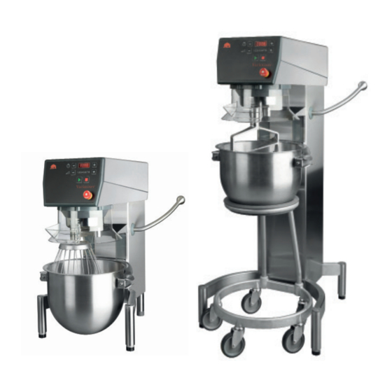
KODIAK user-friendliness: KODIAK has been designed in partnership with kitchen and bakery staff, which has resulted in a number of user benefits: The machine itself: Can be connected to the power grid by the user (100V-240V). Is made of stainless steel. The floor model has height-adjustable feet to ensure that the high bowl trolley works properly. -
Page 11: Operating The Mixer
Operating the machine: Timer (timer field) Increase time Decrease time Increase speed Decrease speed Speed indicator Start Emergency stop Stop Before starting the machine: Display of running time – Timer function: Floor model: Place the bowl in the bowl trolley. Put the desired Select a running time for the machine by pressing next tool into the bowl and wheel it into position between the bowl... -
Page 12: Overloading And Procedure In Case Of Overloading
Overloading: Correct use of tools: Recommended uses of tool: The machine must not be overloaded. Whip Beater Hook Possible overload situations: Cream Cake mix Bread dough Egg whites Buttercream Rye bread • Working with excessively tough and heavy dough Mayonnaise Waffle mix etc. -
Page 13: Systematic Maintenance
Systematic maintenance: Part Action Frequency Note Safety guard Check the safety of the safety guard: Regularly If the tool does not immediately Does the tool stop rotating when the stop rotating on tilting/removal of safety guard is tilted/removed? the safety guard, the machine must not be used. -
Page 14: Error Codes And Possible Solutions
Error codes and possible solutions: For some errors, the control system will show an error code in the display: User pressed without raising the bowl to working height. Solution: Raise bowl to working height. User pressed without fitting the safety guard. Solution: Fit the safety guard. - Page 15 Mixer Spare Parts...
-
Page 16: Mixer Spare Parts
Mixer Spare Parts TABLE OF CONTENTS TRANSMISSION ...........................17 LIFTING SYSTEM .........................18 PLANETARY HEAD ........................20 ATTACHMENT DRIVE ........................22 MACHINE COLUMN ........................24 FREQUENCY INVERTER ......................26 FRONT PANEL ..........................27 CABLES ............................28 ACCESSORIES ..........................30 CIRCUIT DIAGRAM: ........................31... -
Page 17: Transmission
TRANSMISSION ITEM Part number Name Used for RN20-87 CR30-90 Micro-V PJ1016-12 STA3410 Circlip A25 STA3413 Circlip A18 100/115/120/230/400/440/480V CR20-61.3 Mounting plate motor CR30-61.3 Mounting plate motor 200/208V CR20-128 Pulley ø63 J12 CR20-129 Pulley ø112 J12 STA2037 Pasfeder A 8x7x22mm STA3407 Circlip A19 STA2004 Pasfeder AB 6x6x27mm... -
Page 18: Lifting System
LIFTING SYSTEM ITEM Part number Name CR30-83.1M Lifting bolt STA2515 Bearing bushing STA3410 Circlip CR30-63M Crankshaft CR20-62M Lifting arm CR30-62.9 Cover STA3408 Circlip CR20-23M Bowl arm CR20-68.5 Shaft CR30-63.3 Absorber plug CR20-110 Spring CR20-23.5 Gasket STA3403 Circlip STA2019 Feather Key... - Page 19 LIFTING SYSTEM...
-
Page 20: Planetary Head
PLANETARY HEAD ITEM Part number Name STA6460 Dowel pin ø8x24-KS4 STA3515 Retainning ring J55 6006 2RS Ballring 6006 6206 2RS Ballring 6206 STA3518 Retainning ring J62 BK1816 Needel bearing R20-235 Axial washer LR17 Bushing STA3470 Circlip SW17 R20-32 Tooth wheel 1 R20-31 Tooth wheel STA2008... - Page 21 PLANETARY HEAD...
-
Page 22: Attachment Drive
ATTACHMENT DRIVE ITEM Part number Name STA3410 Circlip A25 R100-143 Spacer RN20-37 Distance bushing STA3512 Circlips Type J 47x1,75 STA2031 Feather Key 8x7x30 RN20-9 Worm wheel 6005 2RS Ballring 6005 2RS STA3127 O-ring ø66x2 CR20-8.6M Bearring house machined CR30-50.6R Attachment drive shaft CR30 #12 CR30-211 Attachment drive collar STA5625... - Page 23 ATTACHMENT DRIVE...
-
Page 24: Machine Column
MACHINE COLUMN ITEM Part number Name Used for Machine frame STA5707 Socket head screw M4x16 CR30-304 Cover plate 56CR20P-22 Safety guard 20L 56CR30-109 Micro switch ring CR20-21R Top cover STA5750 Hex cap screw M6x16 STA5842 Hexagon locknut M8 CR30-22.18 Wring STA5028 M6 Captive marine screw 56CR20-110M... - Page 25 MACHINE COLUMN...
-
Page 26: Frequency Inverter
FREQUENCY CONVERTER Part number Name Used for WR20-552.5M Frequency converter 700W 100/115/120/ WR30-552.4M Frequency converter 1500W 200/208V WR20-552.4M Frequency converter 700W 400/440/480V... -
Page 27: Front Panel
FRONT PANEL Part number Name Used for CR10-174.35Z Emergency stop complete CR20-501.4M Front panel mounted 100/115/120V CR20-501.5M Front panel Attachment drive mounted 100/115/120V CR20-501.8M Front panel mounted 200/208V CR20-501.9M Front panel attachment drive mounted 200/208V CR20-501M Front panel mounted 400/440/480V 400/440/480V CR20-501.1M Front panel attachment drive mounted... -
Page 28: Cables
CABLES Part number Name CR10-194.10 Modbus cable STA7256 Crossover adapter CR20-194.5M Earth cable short V20K CR20-194.6M Earth cable long V20K CR30-194.7M Earth cable with ringterminal M6 CR20-194.25M Cable for contactor CR20-194.26M Cable security imput CR20-194.27M Cable for frequency converter to front Used for CR20-542 Main cable... - Page 29 CABLES...
-
Page 30: Accessories
ACCESSORIES ITEM Part number Name Sold As CR20-27.2M Beater 20K VBEAT-20K CR20-28M Whip 20K VWHIP-20K CR20-78M Hook 20K VHOOK-20K CR20-75M Bowl 20K VBOWL-20K CR20-27A2M Flat Beater 20/12 VBEAT12-20K CR20-28AM Whip 20/12 VWHIP12-20K RN20-78AM Hook 20/12 VHOOK12-20K CR20-75AM Bowl 20/12 VBOWL12-20K 42CR20P Scraper complete VSCRP-20K... -
Page 31: Circuit Diagram
CIRCUIT DIAGRAM... - Page 32 Varimixer 2215 East River Road Dayton, OH 45439, US P: (800) 222-1138 E: mixer@varimixer.com www.varimixerusa.com...
Need help?
Do you have a question about the KODIAK V20K and is the answer not in the manual?
Questions and answers