Table of Contents
Advertisement
Quick Links
SPECIFICATION
Wingspan
Length
Weight
Parts listing required (not included)
Engine
Motor side : Power 46
Recommended Motor Battery : 14.8V 4S 4.000mAh LIPO
Radio
Servo
Instruction Manual book
:
1,700mm.
:
1,400 mm.
:
3,3 kg.
:
55 -61
72
10cc gas
:
05 channels.
:
07 servos
66.93 in.
55.12 in.
7.26lbs
2stroke
4 stroke
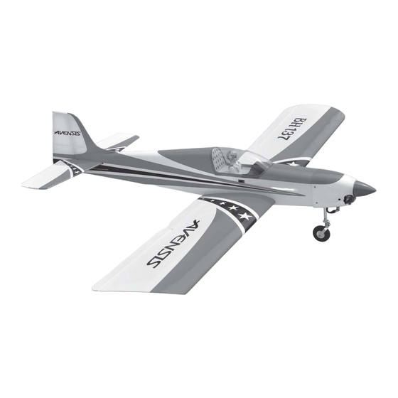
ITEM CODE:BH137
Made in Vietnam.
Advertisement
Table of Contents

Subscribe to Our Youtube Channel
Related Manuals for arf AVENSIS


Summary of Contents for arf AVENSIS
- Page 1 Instruction Manual book ITEM CODE:BH137 SPECIFICATION Wingspan 1,700mm. 66.93 in. Length 1,400 mm. 55.12 in. Weight 3,3 kg. 7.26lbs Parts listing required (not included) Engine 55 -61 2stroke 4 stroke...
- Page 2 Instruction Manual Item code: BH137 This instruction manual is designed to help you build a great flying aeroplane. Please read this manual thoroughly before starting assembly of your AVENSIS. Use the parts listing below to identify all parts. WARNING. Please be aware that this aeroplane is not a toy and if assembled or used incorrectly it is capable of causing injury to people or property.
-
Page 3: Safety Precaution
AVENSIS - Instruction Manual Item code: BH137 Caution: this model is not a toy! If you are a beginner to this type of powered model, please ask an experienced model flyer for help and support. If you attempt to operate the model without knowing what you are doing you could easily injure yourself or somebody else. - Page 4 AVENSIS - Instruction Manual Item code: BH137 REPLACEMENT LARGE PARTS A. Cowling. D . Horizontal stabilizer. B. Wing panel. E. Vertical stabilizer C. Fuselage. F. Aluminium wing dihedral brace. REPLACEMENT SMALL PARTS 1. Aluminium landing gear. 2. Wheels 3.Steering arm.
-
Page 5: Installing The Aileron Servos
AVENSIS - Instruction Manual Item code: BH137 I. AILERON. Assemble then apply drops of thin C/A to center of hinge,on both sides. 1.INSTALLING THE AILERON SERVOS. 1) Install the rubber grommets and brass eyelets onto the aileron servos. - Page 6 AVENSIS - Instruction Manual Item code: BH137 3) Using the thread as a guide and using masking tape, tape the servo lead to the end Secure of the thread: carefully pull the thread out. When you have pulled the servo lead out, re- move the masking tape and the servo lead from the thread.
-
Page 7: Installing The Aileron Linkages
AVENSIS - Instruction Manual Item code: BH137 M2 clevis. Snap keeper. M2 lock nut. bend 3. Plug the aileron servo into the receiver and center the servo. Install the servo arm onto the servo. The servo arm should be perpen-... -
Page 8: Installing The Flap Servos
AVENSIS - Instruction Manual Item code: BH137 Flap Servo tray Flap Electric wire thread Aileron Repeat the procedure for the other wing half. II. FLAP. 1.INSTALLING THE FLAP SERVOS. - Page 9 AVENSIS - Instruction Manual Item code: BH137 2x10mm. Flap control horn. Secure. 3.INSTALLING THE FLAP 3. INSTALLING THE FLAP LINKAGES. LINKAGES. Installing the flap linkages as pictures below. Repeat the procedure for the other wing half. 2.INSTALLING THE FLAP CONTROL HORN.
- Page 10 AVENSIS - Instruction Manual Item code: BH137 Bottom side. bend Repeat the procedure for the other wing half. INSTALLING ENGINE MOUNT. See pictures below: 3x20mm. 4x25mm Front view. Drill a hole 4mm diameter.
-
Page 11: Nose Gear Installation
AVENSIS - Instruction Manual Item code: BH137 NOSE GEAR INSTALLATION. Installing steering arm as follow Steering arm. Attach the pushrod wire to the steering Bottom side. arm. -
Page 12: Installing The Engine
AVENSIS - Instruction Manual Item code: BH137 Secure Mark point Install the nose gear and secure it. Drill a hole 3.5mmdiameter. INSTALLING THE ENGINE. Locate the long piece of wire used for the throttle pushrod. One end of the wire has been pre-bend in to a “Z”... -
Page 13: Installing The Stopper Assembly
AVENSIS - Instruction Manual Item code: BH137 bottom side Pushrod wire. Right side. FUEL TANK. INSTALLING THE STOPPER ASSEMBLY Pushrod wire silicon tube not included. 1. The stopper has been pre-assembled at the factory. Fuel pick- up tube Vent tube... - Page 14 AVENSIS - Instruction Manual Item code: BH137 When the stopper assembly is installed 8. Feed three lines through the fuel tank in the tank, the top of the vent tube should compartment and through the pre-drilled hole rest just below the top surface of the tank.
- Page 15 AVENSIS - Instruction Manual Item code: BH137 COWLING. Trim and cut after. 1. Slide the fiberglass cowl over the en- gine and line up the back edge of the cowl with the marks you made on the fuselage. Top side.
-
Page 16: Installing The Spinner
AVENSIS - Instruction Manual Item code: BH137 INSTALLING THE SPINNER. Install the spinner backplate, propeller and spinner cone. The spinner cone is held in place using two 3mm x 12mm wood screws. Left side. 3x 12mm 3 x 12mm Front view. - Page 17 AVENSIS - Instruction Manual Item code: BH137 secure. INSTALLING THE THROTTLE SERVO. 1. Install one adjustable metal connector through the third hole out from the center of one servo arm, enlarge the hole in the servo arm using a 2mm drill bit to accommodate the servo connector.
- Page 18 AVENSIS - Instruction Manual Item code: BH137 1) Assemble and mounting the wheel pants as shown in the following pictures. 5x35mm. 2) Using the hardware provided, mount the main landing gear to the fuselage. Secure.
-
Page 19: Horizontal Stabilizer Installation
AVENSIS - Instruction Manual Item code: BH137 Elevator servo Secure. HORIZONTAL STABILIZER INSTALLATION. Repeat the process for the other wheel. Horizontal stabilize installation . See picture below. Bottom side Bottom side. Bottom side ELEVATOR INSTALLATION. SERVOS INSTALLATION. 1. Install the rubber grommets and brass collets into the elevator servo. - Page 20 AVENSIS - Instruction Manual Item code: BH137 3. Mark the shape of the vertical on the left Assemble then apply drops of thin C/A to center of hinge,on both sides. and right sides onto the horizontal stabilizer using a felt-tip pen...
-
Page 21: Elevator Control Horn Installa- Tion
AVENSIS - Instruction Manual Item code: BH137 6. After the epoxy has fully cured, re- move Epoxy glue the masking tape or T-pins used to hold the stabilizer in place and carefully inspect the glue joints. Use more epoxy to fill in any... -
Page 22: Elevator Pushrod Installation
AVENSIS - Instruction Manual Item code: BH137 E l e v a t o r pushrod A+B Epoxy PLUS glue Bottom side Cut. Elevator Bend. control horn ELEVATOR PUSHROD INSTALLATION. Elevator pushrod install as same as the way of aileron pushrod. -
Page 23: Rudder Servo Installation
AVENSIS - Instruction Manual Item code: BH137 RUDDER SERVO INSTALLATION. Rudder servo install as same as method of elevator servo. See picture below: Rudder servo. Rudder servo. VERTICAL INSTALLATION. See picture below: Elevator pushrod Secure. Cut the covering Snap keep. - Page 24 AVENSIS - Instruction Manual Item code: BH137 Temporary pin to keep hinge centered. Assemble then apply drops of thin C/A to center of hinge,on both sides. 3. Mark the shape of the vertical on the left and right side on the rudder using a felt-tip pen.
-
Page 25: Rudder Control Horn Installa- Tion
AVENSIS - Instruction Manual Item code: BH137 Top side. C/A glue. Epoxy glue. 5. Put the vertical stabilizer back in place. Using a triangle, check to ensure that the vertical stabilizer is aligned 90 de- gree to the horizontal stabilizer. -
Page 26: Rudder Pushrod Installation
AVENSIS - Instruction Manual Item code: BH137 A+B Epoxy PLUS glue. R u d d e r pushrod Top side. Rudder control horn. RUDDER PUSHROD INSTALLATION. bend. Rudder pushrod install as same as the way of aileron pushrod. M2 lock nut. -
Page 27: Installing The Switch
AVENSIS - Instruction Manual Item code: BH137 Cut. Cut. Rudder pushrod INSTALLING THE SWITCH. 1. Cut out the switch hole using a modeling knife. Use a 2mm drill bit and drill out the two mounting holes through the fuselage side. -
Page 28: Wing Attachment
AVENSIS - Instruction Manual Item code: BH137 WING ATTACHMENT. INSTALLING THE RECEIVER AND BATTERY. 1.Locate the aluminium wing dihedral brace. 1. Plug the servo leads and the switch lead into the receiver. You may want to plug... - Page 29 AVENSIS - Instruction Manual Item code: BH137 See picture wing attach to fuselage. Installing the fuselage hatch as same as pic- ture below. Top side. Left side. 3.Insert two wing panels as pictures be- low. Top side Secure. Secure.
-
Page 30: Control Throws
5) Check the receiver antenna . It should be fully extended and not coiled up inside the fuselage. 6) Properly balance the propeller. We wish you many safe and enjoy- able flights with your AVENSIS.
Need help?
Do you have a question about the AVENSIS and is the answer not in the manual?
Questions and answers