
Related Manuals for arf Tornado


Summary of Contents for arf Tornado
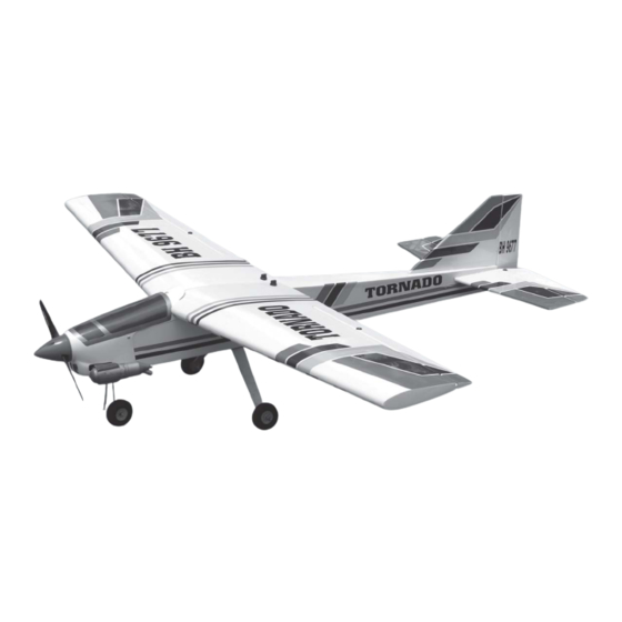
- Page 1 Instruction Manual book SPECIFICATION Wingspan : 1,460 mm 57.5 in. Length 1,270 mm 50 in. Weight 2.6 kg 5.7 Lbs. Radio 04 channels. Servo 05 servos. Engine 40 -46 2 Stroke. 4 Stroke. Made in Vietnam.
- Page 2 TONADO. Instruction Manual This instruction manual is designed to help you build a great flying aeroplane. Please read this manual thoroughly before starting assembly of your TORNADO. Use the parts listing below to identify all parts. WARNING. Please be aware that this aeroplane is not a toy and if assembled or used incorrectly it is capable of causing injury to people or property.
-
Page 3: Safety Precaution
TORNADO. INSTRUCTION MANUAL 2. Using a modeling knife, remove the SAFETY PRECAUTION. covering servo tray. + This is not a toy + Be sure that no other flyers are using your radio frequency. + Do not smoke near fuel + Store fuel in a cool, dry place, away from children and pets. - Page 4 TONADO. Instruction Manual Electric wire. Repeat the procedure for the other wing half. 5. Instal servo tray with aileron servo into the wing as same as picture below. INSTALLING THE AILERON CONTROL HORN. Nilon control clasp. Wing. Servo tray. M3 lock nut. 3x40mm.
- Page 5 TORNADO. INSTRUCTION MANUAL Aileron control horn aileron 3. Install control horn as same as picture below. C/A glue Control horn. Bottom side. Repeat the procedure for the other wing half.
-
Page 6: Installing The Aileron Linkages
TONADO. Instruction Manual INSTALLING THE AILERON LINKAGES. 1. Working with the aileron linkage for now, thread one clevis onto one of the threaded wires. Bottom side. 2. Attach the clevis to the outer hole in the control horn. Install a silicone tube on the clevis. - Page 7 TORNADO. INSTRUCTION MANUAL FUEL TANK. INSTALLING THE STOPPER ASSEMBLY 1. The stopper has been pre-assembled at the factory. 2. Using a modeling knife, cut one length of Remove covering. silicon fuel line (the length of silicon fuel line is calculated by how the weighted clunk should rest about 8mm away from the rear of the tank and move freely inside the tank).
-
Page 8: Installing The Engine Mount
TONADO. Instruction Manual 5. Test fit the stopper assembly into the tank. It may be necessary to remove some of the flashing around the tank opening using a modeling knife. If flashing is present, make sure none of it falls into the tank. Push. -
Page 9: Installing The Nose Gear
TORNADO. INSTRUCTION MANUAL Install the wheel and collar. Secure. INSTALLING THE NOSE GEAR. INSTALLING THE ENGINE. Locate the long piece of wire used for the throttle pushrod. One end of the wire has been pre-bend in to a “Z” bend at the factory. This “Z”... - Page 10 TONADO. Instruction Manual COWLING. 1. Slide the fiberglass cowl over the en- gine and line up the back edge of the cowl with the marks you made on the fuselage. Trim and cut Secure. Left side. Trim and cut Right side. Pushrod wire.
-
Page 11: Installing The Spinner
TORNADO. INSTRUCTION MANUAL INSTALLING THE SPINNER. Install the spinner backplate, propeller and Bottom side. spinner cone. The spinner cone is held in place using two 3mm x 15mm wood screws. 2. While keeping the back edge of the cowl flush with the marks, align the front of the cowl with the crankshaft of the engine. -
Page 12: Installing Landing Gear
TONADO. Instruction Manual 1. The blind nuts are already mounted INSTALLING LANDING GEAR. inside the fuselage. 2. The holes in the landing gear should be to accept the mounting bolts. 3. Using the hardware provided, mount the main landing gear to the fuselage. -
Page 13: Horizontal Stabilizer Installa- Tion
TORNADO. INSTRUCTION MANUAL HORIZONTAL STABILIZER INSTALLA- TION. 1. Using a modeling knife, cut away the covering from the fuselage for the stabilizer and remove it. ELEVATOR INSTALLATION. SERVO INSTALLATION. Remove covering. 1. Install the rubber grommets and brass collets into the elevator servo. Test fit the servo into the servo tray. -
Page 14: Elevator Control Horn Installa- Tion
TONADO. Instruction Manual 5. When you are sure that everything is aligned correctly, mix up a generous amount of 30 minute epoxy. Apply a thin layer to the top and bottom of the stabilizer mounting area and to the stabilizer mounting platform sides in the fuselage. - Page 15 TORNADO. INSTRUCTION MANUAL Nilon M3 lock nut control clasp. 3mm x 40mm. Remove Control horn of elevator. covering. Mark point Drill 1 hole with 6 mm diameter.
-
Page 16: Elevator Pushrod Installation
TONADO. Instruction Manual ELEVATOR PUSHROD INSTALLATION. Secure. Elevator pushrod install as same as the way of aileron pushrod. Elevator pushrod. Cut. Elevator Elevator pushrod. pushrod. Bend and cut. Bottom side. Top side. -
Page 17: Vertical Stabilizer Installation
TORNADO. INSTRUCTION MANUAL VERTICAL STABILIZER INSTALLATION. Hinge. 1) Using a modeling knife, remove the covering from the top of the fuselage and the covering from over the precut hinge slot cut into the lower rear portion of the fuselage This slot accepts the lower vertical. - Page 18 TONADO. Instruction Manual and re-align. Double check all of your meas- urements once more before the epoxy cures. Remove any excess epoxy using a paper towel and rubbing alcohol and hold the stabi- lizer in place with T-pins or masking tape. Al- low the epoxy to fully cure before proceeding.
-
Page 19: Rudder Pushrod Installation
TORNADO. INSTRUCTION MANUAL Rudder mark point control horn. Rudder pushrod. Drill 6mm diameter a hole of the mounting rudder control horn on to the rudder. Elevator Elevator pushrod. pushrod. Rudder pushrod. RUDDER PUSHROD INSTALLATION. Rudder pushrod install as same as the way of aileron pushrod. -
Page 20: Installing The Throttle Pushrod
TONADO. Instruction Manual INSTALLING THE THROTTLE PUSHROD. 1. Install one adjustable metal connector through the third hole out from the center of one servo arm, enlarge the hole in the servo arm using a 2mm drill bit to accommodate the servo connector. -
Page 21: Installing The Switch
TORNADO. INSTRUCTION MANUAL Nose gear pushrod. Rudder pushrod. Elevator pushrod. Throttle pushrod. INSTALLING THE SWITCH. INSTALLING THE RECEIVER AND BATTERY. 1. Plug the servo leads and the switch 1. Cut out the switch hole using a modeling lead into the receiver. You may want to plug knife. -
Page 22: Wing Attachment
TONADO. Instruction Manual 4. Using a 2mm drill bit, drill a hole through the side of the fuselage, near the receiver, for the antenna to exit. Secure. Receiver. WING ATTACHMENT. Wing bolt. Insert. -
Page 23: Control Throws
TORNADO. INSTRUCTION MANUAL BALANCING. CONTROL THROWS. 1) It is critical that your airplane be bal- anced correctly. Improper balance will cause 1. We highly recommend setting up a plane your plane to lose control and crash. using the control throws listed.
Need help?
Do you have a question about the Tornado and is the answer not in the manual?
Questions and answers