Table of Contents
Advertisement
Chapter 1. Getting
Started
Getting Started
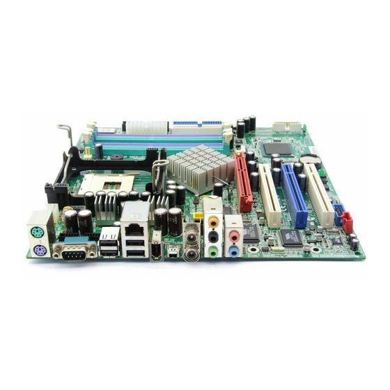
Thank you for purchasing the MS-6747 v1.X M-ATX
mainboard. The MS-6747 is based on Intel
ICH5/ICH5R chipsets for optimal system efficiency. Designed
to fit the advanced Intel
package, MS-6747 delivers a high performance and professional
desktop platform solution.
Pentium 4 processor in the 478-pin
®
Getting Started
865PE & Intel
®
®
1-1
Advertisement
Table of Contents

Related Manuals for MSI MS-6747


Summary of Contents for MSI MS-6747
-
Page 1: Chapter 1. Getting
Getting Started Chapter 1. Getting Started Getting Started Thank you for purchasing the MS-6747 v1.X M-ATX mainboard. The MS-6747 is based on Intel 865PE & Intel ® ® ICH5/ICH5R chipsets for optimal system efficiency. Designed to fit the advanced Intel Pentium 4 processor in the 478-pin ®... -
Page 2: Mainboard Specifications
MS-6747 M-ATX Mainboard Mainboard Specifications Supports Socket 478 for Intel ® Pentium 4 (Socket 478) processor Supports Socket 478 for Intel Northwood/Prescott processor ® Supports up to 3.2 GHz or higher speed P4 processor Chipsets Intel Springdale-865PE chipset ® - Supports AGP 8x/4x at 0.8V (AGP 3.0) or 4x at 1.5V (not supports 3.3V) - Supports 133/166/200MHz memory FSB - Supports 400/533/800MHz Intel NetBurst micro-architecture bus. - Page 3 Getting Started - 1 parallel port supports SPP/EPP/ECP mode - 7 USB 2.0 / 1.1 ports (Rear*4 / Front*3) - 1 Front USB 2.0 / 1.1 port for Card Reader - 1 Line-In / 3 Line-Out / 1 Mic - 1 RJ45 connector - 2 1394 ports (4 Pins*1 / 6 Pins*1) - 1 SPDIF OUT/IN Audio...
-
Page 4: Mainboard Layout
Mini IEEE 1394 Port T:SPDIF-In Intel B:SPDIF-Out 865PE 6 Channel Line-Out T:Mic B:Line-In AGP Slot VT6306 F_P1 PCI Slot 1 VT6105L PCI Slot 2 ICH5 ICH5R PCI Slot 3 Codec BATT MINIPCI1 JBAT1 JSPDIF1 JVIDEO1 JAUDIO1 JBIOS1 MS-6747 v1.X M-ATX Mainboard... -
Page 5: Chapter 2. Hardware
Hardware Setup Chapter 2. Hardware Setup Hardware Setup This chapter tells you how to install the CPU, memory modules, and expansion cards, as well as how to setup the jump- ers on the mainboard. Also, it provides the instructions on con- necting the peripheral devices, such as the mouse, keyboard, etc. -
Page 6: Quick Components Guide
MS-6747 M-ATX Mainboard Quick Components Guide JPW1, p.2-10 CPU, p.2-3 DDR DIMMs, p.2-7 JLPT, p.2-27 CFAN1, p.2-18 ATX1, p.2-10 Back Panel I/O, p.2-12 FDD1, p.2-16 IDE2, p.2-17 J8, p.2-21 J7, p.2-20 IDE1, p.2-17 AGP slot, p.2-30 F_P1, p.2-24 PCI slots, p.2-30 SATA1/SATA2, p.2-22... -
Page 7: Central Processing Unit (Cpu)
Hardware Setup Central Processing Unit: CPU The mainboard supports Intel Pentium 4/Celeron Northwood/Prescott ® ® processor in the 478 pin package. The mainboard uses a CPU socket called PGA478 for easy CPU installation. When you are installing the CPU, make sure the CPU has a heat sink and a cooling fan attached on the top to prevent overheating. -
Page 8: Cpu Installation Procedures For Socket 478
MS-6747 M-ATX Mainboard CPU Installation Procedures for Socket 478 Please turn off the power and Open Lever unplug the power cord before installing the CPU. Sliding 90 degree Plate Pull the lever sideways away from the socket. Make sure to raise the lever up to a 90- degree angle. -
Page 9: Installing The Cpu Fan
Hardware Setup Installing the CPU Fan As processor technology pushes to faster speeds and higher performance, thermal management becomes increasingly important. To dissipate heat, you need to attach the CPU cooling fan and heatsink on top of the CPU. Follow the instructions below to install the Heatsink/Fan: 1. - Page 10 MS-6747 M-ATX Mainboard 5. Connect the fan power cable from the mounted fan to the 3-pin fan power connector on the board. fan power cable MSI Reminds You... Overheating Overheating will seriously damage the CPU and system, al- ways make sure the cooling fan can work properly to protect the CPU from overheating.
-
Page 11: Introduction To Ddr Sdram
Hardware Setup Memory The mainboard provides 4 slots for 184-pin DDR SDRAM DIMM (Double In-Line Memory Module) modules and supports the memory size up to 4GB. You can install DDR400/DDR333/DDR266 modules on the DDR DIMM slots (DDR 1~4). DDR DIMM Slots (DDR 1~4) Introduction to DDR SDRAM DDR (Double Data Rate) SDRAM is similar to conventional SDRAM,... -
Page 12: Ddr Population Rules
MS-6747 M-ATX Mainboard DDR Population Rules Install at least one DIMM module on the slots. Each DIMM slot sup- ports up to a maximum size of 1GB. Users can install either single- or double- sided modules to meet their own needs. Please note that Channel A DIMMs (DIMM1 &... -
Page 13: Installing Ddr Modules
3. The plastic clip at each side of the DIMM slot will automatically close. Volt Notch MSI Reminds You... You can barely see the golden finger if the module is properly inserted in the socket. -
Page 14: Power Supply
MS-6747 M-ATX Mainboard Power Supply The mainboard supports ATX power supply for the power system. Be- fore inserting the power supply connector, always make sure that all compo- nents are installed properly to ensure that no damage will be caused. -
Page 15: Back Panel
Hardware Setup Back Panel The back panel provides the following connectors: 6 Channel L-Out Mouse SPDIF-In IEEE1394 Ports Keyboard COM A SPDIF-Out L-In Mouse Connector The mainboard provides a standard PS/2 mouse mini DIN connector ® for attaching a PS/2 mouse. -
Page 16: Keyboard Connector
MS-6747 M-ATX Mainboard Keyboard Connector The mainboard provides a standard PS/2 keyboard mini DIN connec- ® tor for attaching a PS/2 keyboard. You can plug a PS/2 keyboard directly ® ® into this connector. Pin Definition SIGNAL DESCRIPTION Keyboard DATA... -
Page 17: Usb Connectors
Hardware Setup USB Connectors The mainboard provides a UHCI (Universal Host Controller Interface) Universal Serial Bus root for attaching USB devices such as keyboard, mouse or other USB-compatible devices. You can plug the USB device directly into the connector. USB Port Description SIGNAL DESCRIPTION -Data 0... - Page 18 MS-6747 M-ATX Mainboard SPDIF Connectors The SPDIF connectors privided on the back pannel can be used to con- nect your digital audio equipment. SPDIF SPDIF IEEE1394 Ports The mainboard provides two IEEE 1394 ports. The mini IEEE1394 port is designed for you to connect the IEEE1394 device with external power.
-
Page 19: Audio Port Connectors
Hardware Setup Audio Port Connectors Line Out is a connector for Speakers or Headphones. Line In is used for external CD player, Tape player, or other audio devices. Mic is a connec- tor for microphones. Line-Out (subwoofer speaker) Line-Out (rear speakers) Line-In Line-Out (front speaker) -
Page 20: Floppy Disk Drive Connector: Fdd1
MS-6747 M-ATX Mainboard Connectors The mainboard provides connectors to connect to FDD, IDE HDD, case, modem, LAN, USB Ports, IR module and CPU/System/Power Supply FAN. Floppy Disk Drive Connector: FDD1 The mainboard provides a standard floppy disk drive connector that supports 360K, 720K, 1.2M, 1.44M and 2.88M floppy disk types. -
Page 21: Hard Disk Connectors: Ide1 & Ide2
IDE2 (Secondary IDE Connector) IDE2 can also connect a Master and a Slave drive. MSI Reminds You... If you install two hard disks on cable, you must configure the second drive to Slave mode by setting its jumper. Refer to the hard disk documentation supplied by hard disk vendors for jumper setting instructions. -
Page 22: Fan Power Connectors: Cfan1
MS-6747 M-ATX Mainboard Fan Power Connectors: CFAN1 The CFAN1 (processor fan) supports system cooling fan with +12V. It supports three-pin head connector. When connecting the wire to the connectors, always take note that the red wire is the positive and should be connected to the +12V, the black wire is Ground and should be connected to GND. -
Page 23: Front Panel Audio Connector: Jaudio1
MIC_IN Line_Next_R MIC_IN_S Line_Next_L MSI Reminds You... If you don’t want to connect to the front audio header, pins 1 & 2, 3 & 4 have to be jumpered in order to have signal output directed to the rear audio ports. Otherwise, the Line-Out connector on the back panel will not function. - Page 24 MS-6747 M-ATX Mainboard IEEE 1394 Connector: J7 The mainboard provides one IEEE1394 connector with housing that allows you to connect optional IEEE 1394 ports. Pin Definition SIGNAL SIGNAL IEGND TPA0- TPA0+ Power Power TPB0+ TPB0- IEGND 2-20...
- Page 25 Hardware Setup Joystick/Game Connector: J8 You can connect a joystick or game pad to this connector. J9 Pin Definition Description Description FVCC5 (power) Key pin 2-21...
-
Page 26: Serial Ata Connectors: Sata1 / Sata2
MS-6747 M-ATX Mainboard Serial ATA Connectors: SATA1 / SATA2 The mainboard has dual high-speed Serial ATA interface connectors, SATA1 & SATA2. Each supports 1 generation serial ATA data rates of 150 MB/s. Both connectors are fully compliant with Serial ATA 1.0 specifications. - Page 27 Optional Serial ATA cable connect to the hard disk devices Connect to SATA1 or SATA2 MSI Reminds You... Please do not fold the serial ATA cable in a 90-degree angle, which will cause the loss of data during the transmission. 2-23...
- Page 28 MS-6747 M-ATX Mainboard Video-In Connector: JVIDEO1 The connector is for CD-ROM video connector. JVIDEO1 Front Panel Connector: F_P1 The mainboard provides one front panel connector for electrical con- nection to the front panel switches and LEDs. PS-ON PWR_LED HDD_LED Reset...
-
Page 29: Front Usb Connector: Jusb1
Hardware Setup Front USB Connector: JUSB1 The mainboard provides one USB 2.0 pin header JUSB1 (optional USB 2.0 bracket available) that is compliant with Intel I/O Connectivity Design ® Guide. USB 2.0 technology increases data transfer rate up to a maximum throughput of 480Mbps, which is 40 times faster than USB 1.1, and is ideal for connecting high-speed USB interface peripherals such as USB HDD, dig- ital cameras, MP3 players, printers, modems and the like. -
Page 30: Spdif Connector: Jspdif1
MS-6747 M-ATX Mainboard SPDIF Connector: JSPDIF1 The connector is used to connect an optional bracket for SPDIF (Sony & Philips Digital Interconnect Format) digital audio transmission. JSPDIF1 JSPDIF1 Pin Definition Description Description VCC5 VCC3 SPDIF-O SPDIF-I 2-26... - Page 31 Hardware Setup Print Port: JLPT This mainboard provides a pin header, JLPT, for connecting a printer. JLPT Pin Definition DESCRIPTION STROBE DATA0 DATA1 DATA2 DATA3 DATA4 DATA5 DATA6 DATA7 ACK# BUSY SELECT AUTO FEED# ERR# INIT# SLIN# 2-27...
-
Page 32: Clear Cmos Jumper: Jbat1
MS-6747 M-ATX Mainboard Jumpers The motherboard provides the following jumpers for you to set the computer’s function. This section will explain how to change your motherboard’s function through the use of jumpers. Clear CMOS Jumper: JBAT1 There is a CMOS RAM on board that has a power supply from external battery to keep the data of system configuration. -
Page 33: Bios Flash Jumper: Jbios1
Hardware Setup BIOS Flash Jumper: JBIOS1 The jumper is used to lock or unlock the boot block area on BIOS. When unlocked, the BIOS boot block area can be updated. When locked, the BIOS boot block area cannot be updated. JBIOS1 BIOS Flash BIOS Flash... -
Page 34: Pci (Peripheral Component Interconnect) Slots
MS-6747 M-ATX Mainboard Slots The motherboard provides one AGP slot and three 32-bit PCI bus slots. AGP Slot PCI Slots Mini PCI Slot AGP (Accelerated Graphics Port) Slot The AGP slot allows you to insert the AGP graphics card. AGP is an interface specification designed for the throughput demands of 3D graphics. -
Page 35: Pci Interrupt Request Routing
Hardware Setup PCI Interrupt Request Routing The IRQ, acronym of interrupt request line and pronounced I-R-Q, are hardware lines over which devices can send interrupt signals to the microprocessor. The PCI IRQ pins are typically connected to the PCI bus INT A# ~ INT D# pins as follows: Order 1 Order 2...
Need help?
Do you have a question about the MS-6747 and is the answer not in the manual?
Questions and answers