Table of Contents
Advertisement
Available languages
Available languages
FCC-B Radio Frequency Interference Statement
This equipment has been tested and found to comply with the limits for a class B digital device, pursuant to part 15 of
the FCC rules. These limits are designed to provide reasonable protection against harmful interference when the
equipment is operated in a commercial environment. This equipment generates, uses and can radiate radio frequency
energy and, if not installed and used in accordance with the instruction manual, may cause harmful interference to
radio communications. Operation of this equipment in a residential area is likely to cause harmful interference, in
which case the user will be required to correct the interference at his own expense.
Notice 1
The changes or modifications not expressly approved by the party responsible for compliance could void the user's
authority to operate the equipment.
Notice 2
Shielded interface cables and A.C. power cord, if any, must be used in order to comply with the emission limits.
VOIR LA NOTICE D'NSTALLATION AVANT DE RACCORDER AU RESEAU.
This device complies with Part 15 of the FCC Rules. Operation is subject to the following two conditions:
(1) this device may not cause harmful interference, and
(2) this device must accept any interference received, including interference that may cause undesired operation
Micro-Star International
MS-6787
G52-M6787X9
i
Advertisement
Table of Contents

Subscribe to Our Youtube Channel
Related Manuals for MSI MS-6787


Summary of Contents for MSI MS-6787
- Page 1 This device complies with Part 15 of the FCC Rules. Operation is subject to the following two conditions: (1) this device may not cause harmful interference, and (2) this device must accept any interference received, including interference that may cause undesired operation Micro-Star International MS-6787 G52-M6787X9...
- Page 2 Copyright Notice The material in this document is the intellectual property of MICRO-STAR INTERNATIONAL. We take every care in the preparation of this document, but no guarantee is given as to the correctness of its contents. Our products are under continual improvement and we reserve the right to make changes without notice. Trademarks All trademarks are the properties of their respective owners.
- Page 3 Safety Instructions 1. Always read the safety instructions carefully. 2. Keep this User Manual for future reference. 3. Keep this equipment away from humidity. 4. Lay this equipment on a reliable flat surface before setting it up. 5. The openings on the enclosure are for air convection hence protects the equipment from overheating. Do not cover the openings.
- Page 4 Table of Content English...1 Deutsch...17 Français...33 简体中文 ...49 繁體中文 ...63 日本語...77 Nederlands ...93...
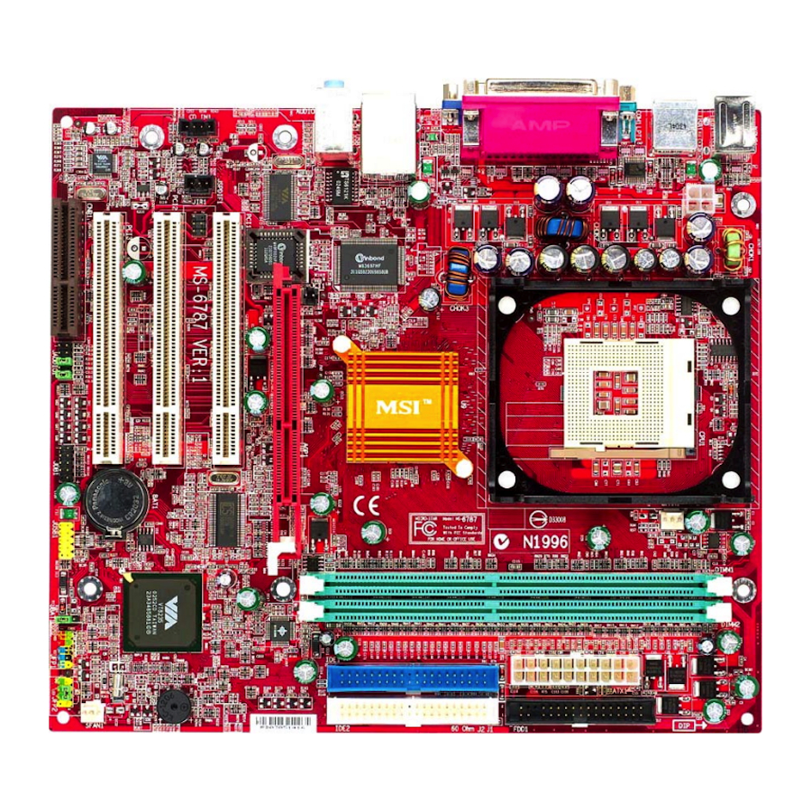
- Page 5 Introduction Thank you for choosing the P4MAM-V Series (MS-6787 v2.X) micro ATX mainboard. The P4MAM-V Series is based on VIA ® VT8751A & VT8235 chipsets for optimal system efficiency. Designed to fit the advanced Intel ® Pentium ® 4 processors in 478 pin package, the P4MAM-V Series delivers a high performance and professional desktop platform solution.
-
Page 6: Specifications
Supports Intel ® Pentium 4/Celeron (Socket 478) processor. Supports Intel ® P4 Northwood up to 3.06GHz and P4 Prescott Celeron up to 2.8GHz. (For the latest information about CPU, please visit http://www.msi.com.tw/program/products/mainboard/mbd/pro_mbd_cpu_support.php ) Chipset VIA ® VT8751A chipset (664 BGA) - 64bit P4 processors FSB I/F (533MHz). - Page 7 On-Board IDE An IDE controller on the VIA ® VT8235 Chipset provides IDE HDD/CD-ROM with PIO, Bus Master and Ultra DMA 33/66/100/133 operation modes. Can connect up to four IDE devices. On-Board Peripherals On-Board Peripherals includes: - 1 floppy port supports 2 FDDs with 360K, 720K, 1.2M, 1.44M and 2.88Mbytes - 1 serial port (COM A) - 1 parallel port supports SPP/EPP/ECP mode - 6 USB 2.0 ports (Rear * 4/ Front * 2)
-
Page 8: Rear Panel
If you do not find the heat sink and cooling fan, contact your dealer to purchase and install them before turning on the computer. (For the latest information about CPU, please visit http://www.msi.com.tw/program/products/mainboard/mbd/pro_mbd_cpu_support.php ) Example of CPU Core Speed Derivation Procedure... -
Page 9: Memory Speed/Cpu Fsb Support Matrix
To dissipate heat, you need to attach the CPU cooling fan and heatsink on top of the CPU. Follow the instructions below to install the Heatsink/Fan: Locate the CPU and its retention mechanism on the motherboard. Position the heatsink onto the retention mechanism. - Page 10 Connect the fan power cable from the mounted fan to the 3-pin fan power connector on the board. MSI Reminds You... Overheating… Overheating will seriously damage the CPU and system, always make sure the cooling fan can work properly to protect the CPU from overheating.
-
Page 11: Power Supply
Volt Power Supply The mainboard supports ATX power supply for the power system. Before inserting the power supply connector, always make sure that all components are installed properly to ensure that no damage will be caused. A 300W or above power supply is suggested. ATX 20-Pin Power Connector: ATX1 This connector allows you to connect to an ATX power supply. -
Page 12: Chassis Intrusion Switch Connector: Jci1 (Optional)
Chassis Intrusion Switch Connector: JCI1 (Optional) This connector is connected to 2-pin connector chassis switch. If the Chassis is open, the switch will be short. The system will record this status. To clear the warning, you must enter the BIOS setting and clear the status. -
Page 13: Ide Connectors: Ide1 & Ide2
MSI Reminds You... 1. Always consult the vendors for proper CPU cooling fan. 2. CFAN1 supports the fan control. You can install the PC Alert utility that will automatically control the CPU fan speed according to the actual CPU temperature. -
Page 14: Front Panel Audio Connector: Jaudio1
AU D_M IC A UD_M IC _ BIAS MSI Reminds You... If you do not want to connect to the front audio header, pins 5 & 6, 9 & 10 have to be jumpered in order to have signal output directed to the rear audio ports. Otherwise, the Line-Out connector on the back panel will not function. -
Page 15: Clear Cmos Jumper: Jbat1
Follow the instructions below to clear the data: K ee p Dat a MSI Reminds You... You can clear CMOS by shorting 2-3 pin while the system is off. Then return to 1-2 pin position. Avoid clearing the CMOS while the system is on; it will damage the mainboard. -
Page 16: Agp (Accelerated Graphics Port) Slot
The CNR slot allows you to insert the CNR expansion cards. CNR is a specially designed network, audio, or modem riser card for ATX family motherboards. Its main processing is done through software and controlled by the motherboard chipset. PCI Interrupt Request Routing The IRQ, abbreviation of interrupt request line and pronounced I-R-Q, are hardware lines over which devices can send interrupt signals to the microprocessor. -
Page 17: Bios Setup
BIOS Setup Power on the computer and the system will start POST (Power On Self Test) process. When the message below appears on the screen, press <DEL> key to enter Setup. DEL: Setup F11: Boot Menu F12: Network boot TAB: Logo If the message disappears before you respond and you still wish to enter Setup, restart the system by turning it OFF and On or pressing the RESET button. -
Page 18: Frequency/Voltage Control
PCI slots to minimize the electromagnetic interference (EMI). Spread Spectrum When the motherboard’s clock generator pulses, the extreme values (spikes) of the pulses creates EMI (Electromagnetic Interference). The Spread Spectrum function reduces the EMI generated by modulating the pulses so that the spikes of the pulses are reduced to flatter curves. If you do not have any EMI problem, leave the setting at Disabled for optimal system stability and performance. - Page 19 CPU Clock Use this item to select the appropriate clock frequency of the CPU host bus. For the complete BIOS introduction and setup, please visit MSI website at http://www.msi.com.tw.
- Page 21 Einleitung Vielen Dank für die Wahl des P4MAM-V Serie (MS-6787 v2.X) Micro ATX Mainboard. Die P4MAM-V Serie basiert auf demVIA ® VT8751A & VT8235 Chipsatz für optimale System-Effizienz. Entwicklet, für den fortschrittlichenIntel ® Pentium ® 4 Prozessor im 478 Pin Gehäuse, liefert die P4MAM-V Serie hohe Perfomanced für eine proffessionelle Desktop-PC Lösung.
-
Page 22: Spezifikationen
Unterstützt Intel ® Pentium 4/Celeron (Socket 478) Prozessor. Unterstützt Intel ® P4 Northwood bis zu 3.06GHz und P4 Prescott Celeron bis zu 2.8GHz. (Für die neuesten CPU-Kompatiblitäts-Informationen besuchen Sie bitte die folgende Webseite: http://www.msi.com.tw/program/products/mainboard/mbd/pro_mbd_cpu_support.php ) Chipsatz VIA ® VT8751A Chipsart (664 BGA) - 64 Bit P4 Processor FSB ISchnittstelle (533MHz). - Page 23 Ultra DMA 33/66/100/133 Funktionsmodis zur Verfügung. Es können bis zu 4 IDE-Laufwerke angeschlossenn werden. On-Board Peripherie On-Board Peripherie beinhaltet: - 1 Floppy Anschluss für bis zu 2 Floppylaufwerke mit 360K, 720K, 1.2M, 1.44M und 2.88 Mbytes. - 1 serieller Anschluss (COMA) - 1 paralleler Anschluss mit SPP/EPP/ECP Unterstützung - 6 USB 2.0/1.1 Anschlüsse (Rückseite * 4 / Frontseite * 2) - 1 Line-In/Line-Ausgang / Mikrophon-Eingang...
-
Page 24: Anschlüsse Auf Der Rückseite
Sie Ihren Händler, um ein passendes Modell erwerben. Bitte schalten Sie den PC nicht ein, wenn Sie keinen geeigneten Kühler installiert haben. (Für die neuesten CPU-Kompatiblitäts- Informationen besuchen Sie bitte die folgende Webseite: http://www.msi.com.tw/program/products/mainboard/mbd/pro_mbd_cpu_support.php ) Beispiel für die Ermittlung des CPU-Kerntaktes Wenn CPU ext. -
Page 25: Installation Des Cpu-Kühlers
Speichertakt / ext. CPU Takt Tabelle Speicher DDR 200 400 MHz 533 MHz CPU Installationsprozedur für Sockel 478 Bitte schalten Sie den PC aus und ziehen das Netzkabel ab, bevor Sie die CPU einsetzen. Klappen Sie den Hebel am CPU-Sockel auf. Stellen Sie sicher, dass er im 90 Grad Winkel aufgeklappt ist. - Page 26 Hinweise des Kühlerherstellers. Schliessen Sie das Versorgungskabel des Lüfters an dem 3-poligen Anschluss des Mainboards an. Er ist mit CPUFAN1 beschriftet. MSI erinnert Sie... Überhitzung… Überhitzung beschädigt Ihre CPU und ds gesamte System ernsthaft, stellen Sie daher sicher, dass die Lüfter immer funktionieren, um die CPU und das System vor Schäden zu bewahren.
- Page 27 Volt Netzteil Das Mainboard benötigt ein ATX-Netzteil für die Stromversorgung. Bevor Sie den Netzteilstecker einsetzen, stellen Sie sicher, dass alle Komponenten korrekt eingesetzt sind. Ein Netzteil mit 300W oder mehr Leistung wird empfohlen. ATX Netzteilanschluss mit 20Kontakten: ATX1 An diesem Anschluss schließen Sie das Netzteil an. Der Netzteilstecker lässt sich nur in einer Richtung einstecken.
- Page 28 720K, 1.2M, 1.44M und 2.88M Kapazität angeschlossen werden können. Anschluss für Chassis Intrusion Schalter: JCI1 (Optional) An diesem 2-Pin Anschluss können Sie einen Gehäuseschalter anschließen. Wenn das Gehäuse geöffnet wird, schließt der Schalter. Das System wird sich diesen Status merken. Sie könnne die damit zusammen hängende Warnung des BIOS im BIOS-Setup wieder zurücksetzen..
- Page 29 MSI erinnert Sie... 1. Verwenden Sie stets einen geeigneten CPU-Lüfter und beachten Sie die Einbauhinweise in diesem Handbuch und in der Lüfterdokumentation. 2. CPUFAN1 unterstützt die Geschwindigkeitsregelung des Prozessorlüfters. Sobald Sie von der Treiber-CD das Windows-Programm PC-Alert installiert haben, wird diese Regelung aktiviert.
- Page 30 AU D_M IC A UD_M IC _ BIAS MSI erinnert Sie... Wenn Sie diesen Audioanschluss nicht verwenden möchten, so müssen die Kontakte 5 & 6, 9 & 10 jeweils mit einem Jumper geschlossen sein, damit der hintere Audio-Ausgang des Mainboards funktioniert..
- Page 31 Sie im ausgeschalteten Zustand den Jumper JBAT1 von Position 1-2 auf 2-3 um. K ee p Dat a MSI erinnert Sie... Schalten Sie den PC vor dem Umsetzen des Jumpers aus. Setzen Sie den Jumper nach ein paar Sekunden wieder in 1-2 zurück und schalten erst dann den PC wieder ein.
- Page 32 PCI (Peripheral Component Interconnect) Steckplätze Ein PCI Steckplatz erlaubt es Ihnen, für Sie erforderliche PCI-Erweiterungskarten in das System einzusetzen. Wenn Sie Erweiterungskarten einsetzen oder entfernen, stellen Sie sicher, dass Sie vorher den PC ausschalten und den Netzstecker abziehen. Lesen Sie auch die Dokumentation der Erweiterungskarte bezüglich Hinweisen des Herstellers zum Einbau und möglichen Hardware- und Softwareeinstellungen.
-
Page 33: Bios Setup
BIOS Setup Wenn Sie den PC einschalten, startet er zuerst die POST-Systemdiagnose (Power On Self Test). Wenn die folgende Meldung angezeigt wird, dann drücken Sie die Taste <Entf> um in das BIOS-Setup zu gelangen. DEL: Setup F11: Boot Menu F12: Network boot TAB: Logo Wenn die Meldung verschwindet, bevor Sie die Taste gedrückt haben, wird es das installierte Betriebssystem starten. -
Page 34: Frequency/Voltage Control
PNP/PCI Configurations Dieser Eintrag wird angezeicht, wenn Ihr System PnP/PCI unterstützt. PC Health Status Dieses Untermenü zeigt Ihnen die Hardwareüberwachung Ihres Systems an. Frequency/Voltage Control Hier können Sie Frequenzen und Betriebsspannungen einstellen. Load Fail-Safe Defaults Benutzen Sie dieses Menü, um die BIOS-Werte zu laden, mit denen die beste System-Performance erreicht wird. - Page 35 Probleme haben, lassen Sie diese Funktion aus, um die Systemkompatibilität zu erhöhen. CPU Clock Hiermit können SIe den CPU-FSB-Takt verändern. Sie, dass eine Änderung hier die Systemstabilität negativ beeinflussen kann, daher wird nicht empfohlen, hier Änderungen zu tätigen. Die komplette Anleitung zum BIOS-Setup finden Sie auf http://www.msi.com.tw.
- Page 37 Introduction Félicitation vous venez d’acheter la carte mère Micro ATX P4MAM-V (MS-6787 v2.X). La P4MAM-V est basée sur les chipsets VIA ® VT8751A & VT8235 vous procurant des performances optimales. La carte mère est destinée aux processeurs Intel ® Pentium ® 4 socket 478, et elle conviendra parfaitement à...
-
Page 38: Spécifications
Supporte les processeurs Intel ® Pentium 4/Celeron (Socket 478). Supporte les Intel ® P4 Northwood jusqu’à 3.06GHz et P4 Prescott Celeron jusqu’à 2.8GHz. (Pour connaître les dernières informations concernant le CPU, veuillez visiter http://www.msi.com.tw/program/products/mainboard/mbd/pro_mbd_cpu_support.php ) Chipset Chipset VIA ® VT8751A (664 BGA) - Processeur P4 - 64bit - FSB I/F (533MHz). - Page 39 IDE Intégré Un contrôleur IDE sur le chipset VIA ® VT8235 procure les modes opératoires IDE HDD/CD-ROM avec PIO, Bus Master et Ultra DMA 33/66/100/. Possibilité de connecter jusqu’à 4 périphériques IDE. Périphériques Intégrés Les périphériques intégrés sont : - 1 port floppy supportant 2 FDD (360K, 720K, 1.2M, 1.44M et 2.88Mbytes) - 1 port série (COM A) - 1 port parallèle supportant les modes SPP/EPP/ECP - 6 ports USB 2.0 (Arrière* 4/ Façade* 2)
-
Page 40: Panneau Arrière
+ ventilateur permettant la dissipation de la chaleur. Pour connaître le modèle de ventilateur nécessaire à la bonne utilisation de votre système n’hésitez pas à contacter votre revendeur. (Pour connaître les dernières informations concernant le CPU, veuillez visiter http://www.msi.com.tw/program/products/mainboard/mbd/pro_mbd_cpu_support.php ) Exemple de Procédure de Dérivation du CPU Core Speed Horloge CPU... - Page 41 Tableau de Support Vitesse Mémoire/CPU FSB Mémoire DDR 200 400 MHz 533 MHz Procédure d’Installation du CPU Socket 478 Veuillez éteindre ou débrancher le PC avant d’installer le CPU. Tirer le levier qui se trouve sur le côté du socket. Assurez-vous que celui-ci est bien relevé (position 90°).
- Page 42 Connecter le câble d’alimentation sur le connecteur de la carte mère prévu à cet effet (3 broches). MSI Vous Rappelle... Surchauffe… La surchauffe peut endommager sérieusement votre CPU ainsi que le système. Il faut toujours s’assurer que le ventilateur fonctionne correctement afin de protéger votre CPU de la surchauffe.
- Page 43 Volt Alimentation La carte mère supporte les alimentations ATX. Avant de brancher le connecteur d’alimentation. Il faut toujours vous assurer que tous les composants sont bien installés afin de ne pas les endommager. Une alimentation 300W ou supérieur est préconisée. Connecteur d’Alimentation ATX 20-broches : ATX1 Ce connecteur vous permet de connecter l’alimentation ATX.
- Page 44 Connecteur Chassis Intrusion Switch : JCI1 (Optionnel) Ce connecteur est relié au connecteur 2 broches “chassis switch”. Si le chassis est ouvert, alors le système va mettre en mémoire cette opération. Pour effacer cette alerte vous devez entrer dans le Bios et effacer cette donnée.
- Page 45 MSI Vous Rappelle... 1. Toujours consulter le vendeur pour connaître le ventilateur à utiliser pour le CPU. 2. CPUFAN1 supporte le contrôle du ventilateur. Vous pouvez installer l’utilitaire PC Alert qui contrôle automatiquement la vitesse de rotation du ventilateur du CPU en fonction de la température du CPU.
- Page 46 AU D _M IC A UD_ M IC _ BIAS MSI Vous Rappelle... Si vous ne voulez pas connecter l’audio en façade à l’aide des broches 5 & 6, 9 & 10 doivent être recouvertes par un cavalier pour envoyer le signal vers les ports audio à l’arrière. Autrement, le connecteur Line-Out à...
- Page 47 JBAT1 (Clear CMOS Jumper). Suivez les instructions ci-dessous pour effacer les données : K ee p Da t a MSI Vous Rappelle... Vous effacez les données en positionnant le cavalier sur les broches 2-3 quand le PC n’est pas allumé.
-
Page 48: Pci Interrupt Request Routing
Slot AGP (Accelerated Graphics Port) Le slot AGP vous permet de connecter une carte graphique. Cette interface est particulièrement bien adaptée aux application 3D. Contrôleur 66MHz, 32-bit avec accès direct à la mémoire principale. La carte mère supporte les cartes AGP 4x. Slots PCI (Peripheral Component Interconnect) Les slots PCI vous permettent la connexion de cartes d’extension selon vos besoins. -
Page 49: Setup Du Bios
Setup du BIOS Lorsque le PC démarre le processus de POST (Power On Self Test) se met en route. Quand le message ci-dessous apparaît, appuyer sur <DEL> pour accéder au Setup. DEL: Setup F11: Menu de Boot F12: Boot réseau TAB: Logo Si le message disparaît avant que n’ayez appuyé... - Page 50 fréquence/voltage. Load High Performance Defaults Utilisez ce menu pour charger les valeurs du BIOS qui donnent les meilleures performances, mais la stabilité du système pourrait être affectée. Load Optimized Defaults Utiliser ce menu pour charger les valeurd définies en usine pour une stabilité du système.. Set Supervisor Password Utiliser ce menu pour entrer un mot de passe superviseur.
- Page 51 EMI. N’oubliez pas de désactiver cette fonction si vous voulez faire de l’overclocking, afin d’éviter tout problème. CPU Clock Utiliser ce paramètre pour sélectionner la bonne fréquence d’horloge du CPU host bus. Pour plus d’informations sur le BIOS, veuillez visiter notre site web à l’adresse suivante http://www.msi.com.tw.
- Page 53 简介 感谢您购买 P4MAM-V 系列(MS-6787 v2.X) micro ATX 主板。P4MAM-V 系列是基于 VIA ® VT8751A & VT8235 芯片组以提高系统性能。P4MAM-V 系列主板是为 478 针脚封装的 Intel ® Pentium ® 4 处理器 身定做的高性能主板,提供了高性能、专业化的桌面平台解决方案。 布局 Top: Mouse B ottom: Keyboard JPW1 Por ts Top: Parallel Port Bott om: COM A...
- Page 54 规格 支持 Intel ® Pentium 4/Celeron (Socket 478) 处理器 支持 Intel ® P4 Northwood 处理器最高达 3.06GHz 和 P4 Prescott Celeron 处理器最高达 2.8GHz. (要了解关于 CPU 的最新信息,请访问 http://www.msi.com.tw/program/products/mainboard/mbd/pro_mbd_cpu_support.php ) 芯片组 VIA ® VT8751A 芯片组(664 BGA) - 64bit P4 处理器 FSB I/F(533MHz) - 64bit DDR SDRAM 内存 I/F(200/266MHz)...
- Page 55 板载 IDE 1 个 IDE 控制器集成于 VIA ® VT8235 芯片组中,提供具有 PIO, Bus Master 和 Ultra DMA 33/66/100/133 的 IDE HDD/CD-ROM 工作模式。最多可连接 4 个 IDE 设备。 板载周边 板载周边包括: - 1 个软驱接口,支持 2 台 360K, 720K, 1.2M, 1.44M 和 2.88 Mbytes 的软驱 - 1 个串行端口(COM A)...
-
Page 56: 中央处理器:Cpu
设备的指导,如鼠标,键盘等。安装时,请谨慎拿各零部件并且按照安装说明的步骤进行。 中央处理器:CPU 本主板支持 478 针脚封装的 Intel Pentium 4 Northwood & Prescott Celeron 处理器。主板使用的是 PGA478 的 CPU 插槽,可使 CPU 安装过程简化。当您在安装 CPU 时,请务必确认您使用的 CPU 带有 防过热的散热片和降温风扇。如果您的 CPU 没有散热片和降温风扇,请与销售商联系,购买或索取以上 设备,并在开机之前妥善安装。 (要了解关于 CPU 的最新信息,请访问 http://www.msi.com.tw/program/products/mainboard/mbd/pro_mbd_cpu_support.php ) CPU 核心速度推导 如果 CPU 时钟频率 核心/总线倍频 那么 CPU 核心频率... - Page 57 内存速率/CPU FSB 支持列表 内存 DDR 200 400 MHz 533 MHz 478 针脚封装的 CPU 安装 安装前请先关掉电源并且拔掉电源线。 将拉杆从插槽上拉起,与插槽成 90 度角。 寻找 CPU 上的圆点/切边。此圆点/切边应指向拉杆的旋轴,只有方向正确 CPU 才能插入。 如果 CPU 是正确安装的,针脚应该完全嵌入进插座里并且不能被看到。请注意任何违反正确操作 的行为都可能导致主板的永久性破坏。 稳固的将 CPU 插入到插座里并且关上拉杆。当拉上拉杆时 CPU 可能会移动,一般关上拉杆时用 手指按住 CPU 的上端以确保 CPU 正确的而且是完全的嵌入进插座里了。 安装 CPU 风扇 在新技术的推动下,使处理器可以运行在更高的频率下,速度更快,效能更好,热量的控制也变得越来...
- Page 58 更换 CPU 更换 CPU 时,请先关闭 ATX 电源供应或拔掉电源插头以确保 CPU 的安全。 内存 主板提供了 2 个 184-pin、2.5V 的 DDR DIMM(双面)插槽。您可安装 DDR200/DDR266/DDR333 DDR SDRAM 内存,支持的最大容量为 2GB。您至少要安装一条内存在插槽,以保证系统正常工作。 (要了解 内存模组支持的更新,请访问 http://www.msi.com.tw/program/products/mainboard/mbd/pro_mbd_trp_list.php ) 至少要安装一条内存模组在插槽。内存模组可以按任何次序被安装。您也可以根据自己的需要,来安装 单面或双面的内存模组。 安装 DDR 内存 DDR DIMM 内存条的中央仅有一个缺口。 将 DDR 内存垂直插入 DDR 插槽中,并确保缺口的正确位置。 DIMM 插槽两边的塑料卡口会自动闭合。...
- Page 59 Volt 微星提醒您... 如果正确插入了内存模组,您将不会看到金手指部分。 电源供应 主板使用 ATX 结构的电源供应器给主板供电。在连接电源供应器之前,请务必确认所有的组件都已正确 安装,并且不会造成损坏。建议您使用功率为 300W 或以上的电源。 ATX 20-Pin 电源接口:ATX1 此接口可连接 ATX 电源供应器。在与 ATX 电源供应器相连时,请务必确认,电源供应器的接头安装方 向正确,针脚对应顺序也准确无误。将电源接头插入,并使其与主板电源接口稳固连接。 GN D G ND PS _ON GN D 5 V_ SB GN D GN D G N D 1 2V P W_ OK ATX 12V 电源接口:JPW1 此...
- Page 60 软盘驱动器接口:FDD1 主板提供了一个标准的软盘驱动器接口 FDD,支持 360K, 720K, 1.2M, 1.44M 和 2.88M 的软盘驱动器。 机箱入侵开关接头:JCI1(选配) 此接头可与一个 2-pin 机箱开关相连。如果机箱被打开了,此接头会短接,系统会记录此状态,并在屏幕 上显示警告信息。要消除这一警告信息,您必须进入 BIOS 设定工具清除此记录。 GN D CI NTRU CD-In 接口:CD_IN1 此接口为 CD-ROM 的音频接口。 GN D SPDIF-OUT 接口:JSPDIF1(选配) 此接口用于连接 SPDIF 界面的接口,以实现数字音频传输。 SPD IF VC C G ND 风扇电源接口:CFAN1/SFAN1 CFAN1(处理器风扇)...
- Page 61 微星提醒您... 1. 请询问厂商以使用适当的 CPU 降温风扇。 2. CFAN1 支持风扇控制,您可以安装 PC Alert 工具,这样它将会自动根据处理器的温度来设定风扇的速 度。 硬盘接口:IDE1 & IDE2 主板有一个 32-bit 增强 PCI IDE 和 Ultra DMA 33/66/100/133 控制器 , 提供 IDE 接口设备工作于 PIO mode 0-4,Bus Master 和 Ultra DMA 33/66/100/ 133 等功能。您共可使用四个 IDE 设备,如硬盘,CD-ROM、 120MB 软驱或其它...
- Page 62 前置音频接口:JAUDIO1 您可以在前置面板接口 JAUDIO1 上连接一个音频接口 , JAUD1 是符合 Intel ®l I/O 面板连接设计向导的 。 AUD _V CC AU D_G ND A UD_RET_R KE Y AUD _RET _ L AUD_FP OUT_ L HP _ON A UD_FP OU T_R AU D_M IC A UD_M IC _ BIAS 微星提醒您...
- Page 63 K ee p Dat a 微星提醒您... 在系统关闭时,您可通过短接 2-3 针脚来清除 CMOS 数据。然后,返回到 1-2 针短接的状态。请避免在 系统开机时清除 CMOS,这样可能会对主板造成损害。 CPU 支持跳线:JP1 此跳线指定了主板是否支持被锁的或某些未被锁的 CPU。 L ock ed CP U IrDA 红外模组接头:JIR1(选配) 此接头可让您连接到 IrDA 红外模组。 GN D IR RX IRTX VC C5 Clear Da ta Un lo cked CP U...
- Page 64 AGP(加速图形端口)插槽 用户可将 AGP 图形卡安装在此 AGP 插槽上。AGP 是一种专为 3D 图形显示而设计的一种接口规范。它 为图形控制器对主内存的直接访问提供一个 66MHz,32-bit 专用通道。本主板支持 4x 的 AGP 卡。 PCI(周边设备连接)插槽 PCI 插槽可安装您所需要的扩展卡。当您在安装或拆卸扩展卡的时候,请务必确认已将电源插头拔除。 同时,请仔细阅读扩展卡的说明文件,安装和设置此扩展卡必须的硬件和软件,比如跳线或 BIOS 设置。 CNR(通讯网络附加卡)插槽 CNR 插槽可让您插入 CNR 扩展卡。CNR 是为 ATX 系列主板的音频或调制解调附加卡而特别设计的。 它的主要功能是通过软件和主板芯片组来工作。 PCI 中断请求队列 IRQ 是中断请求队列和中断请求确认的缩写,将设备的中断信号送到微处理器的硬件列表。PCI 的 IRQ 针脚一般都是连接到如下表所示的 PCI 总线的 INT A# ~ INTD# 引脚: Order1 Order2 PCI Slot 1...
- Page 65 BIOS 设置 计算机加电后,系统将会开始 POST (加电自检)过程。当屏幕上出现以下信息时,按<DEL>键即可进 入设定程序。 DEL: Setup F11: Boot Menu F12: Network boot TAB: Logo 如果此信息在您做出反应前就消失了,而您仍需要进入 Setup,请关机后再开机或按机箱上的 Reset 键, 重启您的系统。您也可以同时按下<Ctrl> <Alt>和<Delete>键来重启系统。 主页面 Standard CMOS Features(标准 CMOS 特性设定) 使用此菜单可对基本的系统配置进行设定。如时间,日期等。 Advanced BIOS Features(高级 BIOS 特性设定) 使用此菜单可对系统的高级特性进行设定。 Advanced Chipset Features(高级芯片组特性设定) 使用此菜单可以修改芯片组寄存器的值,优化系统的性能表现。 Integrated Peripherals(整合周边设定) 使用此菜单可以对周边设备进行特别的设定。...
- Page 66 在此项中终端用户可以通过指定 CPU 的倍频对处理器进行超频(只要 CPU 支持超频) 。 Auto Detect PCI/DIMM Clk(自动侦测 PCI/DIMM 时钟) 此项用于自动侦测 PCI 插槽。当此项设置为 Enabled,系统将从空置的 PCI 插槽中移除(关闭)时钟, 把电磁干扰(EMI)降低到最小程度。 Spread Spectrum(频展) 当主板上的时钟震荡发生器工作时,脉冲的极值(尖峰)会产生 EMI(电磁干扰) 。频率范围设定功能可 以降低脉冲发生器所产生的电磁干扰,所以脉冲波的尖峰会衰减为较为平滑的曲线。如果您没有遇到电 磁干扰问题,将此项设定为 Disabled ,这样可以优化系统的性能表现和稳定性。但是如果您被电磁干扰 问题困扰,请将此项设定为 Enabled,这样可以减少电磁干扰。注意,如果您超频使用,必须将此项禁 用。因为即使是微小的峰值漂移(抖动)也会引入时钟速度的短暂突发,这样会导致您超频的处理器锁 死。 CPU Clock(CPU 时钟) 使用此项可选择 CPU 主机总线的适当时钟频率。 要了解完整的 BIOS 简介和设置,请访问微星网站:http://www.msi.com.tw.
- Page 67 簡介 感謝您購買 P4MAM-V 系列 (MS-6787) v1.X Micro ATX 主機板。P4MAM-V 系列 (MS-6787) v1.X Micro ATX 主機板係採用 VIA ® VT8751A & VT8235 晶片組,可提供您高效能及專業的桌上型電腦平台 解決方案。 主機板配置圖 Top: Mouse B ottom: Keyboard JPW1 Por ts Top: Para llel Port Bott om: COM A VGA Po rt...
- Page 68 主機板規格 中央處理器 支援 Socket 478 架構 Intel 支援 Northwood 處理器最高可達 3.06GHz 和 Prescott Celeron 處理器最高可達 2.8GHz。 (有關更多的處理器訊息,請至微星科技網站:http://cweb.msi.com.tw ) 晶片組 VIA® VT8751A 晶片組(664 BGA) 支援 64 位元 P4 處理器 FSB I/F(533MHz)外頻。 支援 64 位元 DDR SDRAM 記憶體模組 I/F(200/266MHz)。 支援 32 位元 AGP I/F (66MHz) 4x/2x 模組。...
- Page 69 內建週邊輸出 內建週邊包括: 一個軟碟機埠,可支援兩部 360K/720K/1.2M/1.44M/2. 88MB 規格的軟碟機。 一個序列埠(COMA)。 一個平行埠,可支援 SPP/EPP/ECP 模式。 六個 USB2.0 連接埠(背板*4/面板*2)。 一個音效輸入/音效輸出/麥克風輸入埠。 一個 RJ-45 的區域網路接頭。 一個 VGA 連接埠。 音效 VIA 235 晶片上整合內建 AC'97 音效控制器 6 聲道 VIA VT1616 軟體音效 符合 AC97 2.2 規格。 區域網路 LAN VIA VT6103 PCI 匯流排單晶片快速乙太網路控制器 支援外接式...
- Page 70 硬體安裝 本章將教您安裝中央處理器、記憶體模組、擴充卡及設定主機板上的跨接器。附帶並告訴您如何連接滑 鼠鍵盤等週邊裝置。進行安裝時請小心處理零組件並遵守安裝步驟。 中央處理器 本主機板使用 Socket478 規格的 CPU 插槽,支援 Intel Pentium 4 Northwood/ Prescott Celeron 處理 器。當您在安裝 CPU 時,請確認附有散熱器與冷卻風扇以防止 CPU 過熱。如果沒找到散熱器與冷卻風 扇,請洽詢經銷商購買,並在啟動電腦之前,將散熱器正確地安裝在您的主機板上。 (有關更多的 CPU 訊息,請至微星科技網站: http://www.msi.com.tw/program/products/mainboard/mbd/pro_mbd_cpu_support.php ) CPU 核心速度調整說明 CPU 時脈 如果 核心/匯流排比值 CPU 核心速度 則 = 133MHz = 23 = 主時脈...
- Page 71 記憶體速度/CPU FSB 支援對照表 Memory DDR 200 400 MHz 533 MHz 安裝 Socket 478 規格的中央處理器 1. 在安裝中央處理器之前請先把電源關閉並且將電源線拔開。 2. 將側邊的拉桿從插槽拉起,然後將拉桿提升至 90 度角。 3. 找出 CPU 上的標記/切角(此標記/切角應在拉桿末端)。CPU 的安裝具有方向性,僅能以一個正確 方向插入。 4. 如果中央處理器有安裝正確,插梢應該能完全地進入腳座內而且看不到插梢。請注意,任何不正確的 安裝中央處理器,可能會造成主機板永久毀損。 5. 壓下拉捍以完成安裝。當您壓下拉捍的時候,中央處理器還是有可能會移動,請緊緊地按住中央處理 器上方,確定您的中央處理器腳座完全地進入腳座內。. 安裝 CPU 風扇 由於處理器速度愈來愈快,散熱問題也愈來愈重要。為了避免因高速運轉所帶來的過熱問題,您需要安 裝風扇及散熱器。 1. 找出主機板上的處理器插槽和底座。 2. 將散熱器放置在底座上。 3.
- Page 72 MSI 提醒您… 溫度過高 溫度過高將會嚴重損壞您的 CPU 及系統,請確保您的散熱風扇可以正常運作,以保護 CPU,避免發生過 熱的情形。 更換 CPU 當您在更換 CPU 時,為了確保不會損壞 CPU,應該要先關掉 ATX 電源的開關,或將電源線拔掉。 記憶體 本主機板提供兩條 DDR SDRAM DIMM 插槽(184-pin),最高可支援到 2GB 記憶體容量。您可以安裝 PC2100/DDR266 或 PC1600/DDR200 記憶體模組在 DDR DIMM 插槽上。最高可支援 2GB 記憶體。為 避免運作錯誤,您必須安裝至少一個以上的記憶體模組。(有關更多的記憶體模組訊息,請至微星科技網 站:http://cweb.msi.com.tw) 至少要安裝一組 DIMM 模組在主機板上。每一組 DIMM 模組記憶體模組至多可支援 1GB 記憶體,您可...
- Page 73 電源供應器 本主機板的電源系統支援 ATX 電源。在插入電源連接器之前,請務必確認所有的零組件均安裝妥善,以 免造成損壞。我們建議您使用 300 瓦以上的電源供應器。 ATX 20-pin 電源連接器:ATX1 此連接器讓您接上 ATX 電源。連接 ATX 電源時,請確認電源插頭插入的方向正確並對準腳位,然後將 電源緊密地壓入連接器內。 3.3V PS_ON -12V 5V_SB 3.3V PW_OK 3.3V ATX 12V 電源連接器:JPW1 12V 的電源連接器是供中央處理器使用。 軟碟機連接器:FDD 1 本主機板提供了標準的軟碟機連接器,可以連接以下類型的軟碟機:360KB、720KB、1.2MB、1.44MB 及 2.88MB。 機殼開啟警告開關連接器:JCI1(選購) 此連接器是連接到一個 2-pin 的機殼開關。當機殼被打開時,此開關會短路,系統便會記錄此狀態並在...
- Page 74 此連接器可讓您使用 SPDIF(Sony &飛利浦公司數位介面)的數位音效傳輸。 SPD IF VC C G ND 冷卻風扇連接器:CFAN1/SFAN1 CFAN1(處理器冷卻風扇)、SFAN1(系統冷卻風扇),這兩個連接器以+12V 的電壓供應電力給系統的冷卻 風扇。它支援 3-pin 接頭的連接器。當您將電線連接到連接器時,請務必記得紅色線是正極,一定要連 接到+12V,而黑色線是接地線,必須要連接到 GND。假如主機板上內建有系統硬體監控器晶片組,你 必須使用具有速度感應器的特殊設計冷卻風扇才能夠使用 CPU 冷卻風扇控制功能。 +12V SENSOR MSI 提醒您... 請詢問供應商選擇合適的 CPU 風扇。 CFAN1 支援風扇控制器 , 您可安裝 PC Alert 工具程式 , 這個程式會根據 CPU 的實際溫度來控制 CPU 冷卻風扇的速度。...
- Page 75 本主機板具有一個 32 位元增強型 PCI IDE 及 Ultra DMA 33/66/100/133 控制器 , 可提供 PIO 模式 0~4 、 主控匯流排以及 Ultra DMA 33/66/100/133 等功能。你可透過 IDE 連接線連接四部硬碟、CD-ROM 及 其他 IDE 裝置。 第一部硬碟必須連接到 IDE1。IDE1 可以連接一部主要裝置及一部隸屬裝置。您必須根據跳線設定將第 二部裝置設定為隸屬裝置。IDE2 也可連接一部主要裝置及一部隸屬裝置。 MSI 提醒您... 假如您在同一條連接線上安裝了兩組硬碟,您必須設定硬碟的跨接器(Jumper) ,將第二組硬碟指定到隸 屬模式。關於硬碟的設定方式,請參考硬碟廠商所提供之說明。 面板連接器:JFP1 & JFP2 主機板提供兩個面板連接器連接到面板開關及 LED 指示燈。JFP1 的規格符合 Intel 面板輸入/輸出...
- Page 76 MSI 提醒您... 如果您不想連接到此面板音效連接器,則必須用跨接器將連接器上的第 5、6、9 及 10 腳短路,以將音 。 訊輸出導引至背板音效埠 面板 USB 連接器:JUSB1 主機板提供一個面板 USB2.0 連接器 JUSB1,其規格都符合 Intel 面板輸入/輸出設計指南。USB2.0 技術 可大幅提昇資料傳輸速率,最高可達 480Mbps,為 USB1.1 的 40 倍,適用於高速 USB 介面的週邊裝置, 例如:USB 硬碟、數位相機、MP3 播放器、印表機、數據機及相關週邊裝置。 US B1 - US B1 + VC C US BOC...
- Page 77 CPU 支援跨接器:JP1 此跨接器決定主機板將支援鎖定或不鎖定的中央處理器。如果您安裝鎖定的 CPU,請用跨接器將 1-2 腳 短路,如果您安裝不鎖定(可超頻)的 CPU,請用跨接器將 2-3 腳短路。 L ock ed CP U Un lo cked CP U (Locked CPU:支援鎖定 CPU / Unlocked CPU:支援不鎖定 CPU) IrDA 紅外線模組連接器:JIR1(選購) 這個連接器可讓您連接一個 IrDA 紅外線模組。您必須透過 BIOS 設定才能夠使用紅外線功能。JIR1 的 規格符合 Intel 面板輸入/輸出設計指南。 GN D IR RX IRTX VC C5...
- Page 78 AGP 插槽 此插槽能讓您安裝 AGP 顯示卡。AGP 的設計是一個可提升 3D 繪圖處理效能的介面規格。它採用一個 66MHz、32 位元的頻寬當作圖形控制器和主記憶體之間的直接通道。此插槽支援支援 4x/8x 1.5V AGP 顯示卡。 PCI 插槽 此插槽可以讓您安裝各類擴充卡,以滿足你的使用需求。當您要安裝或是移除擴充卡時,請先確認電源 已切斷。另外,請詳讀擴充卡的使用說明,以確認在使用擴充卡時所需要變更的硬體或軟體設定,例如 跨接器、開關或 BIOS 的組態與設定。 CNR 插槽 此插槽可讓您安裝 CNR 卡。CNR 是一個特殊設計的網路、音訊或數據機直立子卡,專門用於 ATX 主機 板上。這個擴充卡主要由軟體處理並由主機板的晶片組控制。 PCI 的中斷要求 IRQ 是中斷要求 (Interrupt request) 的英文縮寫,它是一個可讓裝置傳送中斷訊號至微處理器的硬體線 路。PCI 的 IRQ 腳位通常都連接到 PCI 匯流排的 INT A#~INT D#腳位,如下所示: Order1 Order2 PCI Slot 1...
- Page 79 BIOS 設定 打開電腦的電源後,系統就會開始 POST (開機自我測試)程序。當下列訊息出現在螢幕上時,按下<DEL> 鍵進入設定程式。 DEL:Setup F11:Boot Menu F12:Network boot TAB:Logo 如果此訊息在您反應之前就已消失,而您還想要進入設定時,將系統關閉重新啟動或是按下 RESET 按鈕。 您也可以同時按下 <Ctrl>、<Alt>及<Delete>鍵重新啟動系統。 主選單 Standard CMOS Features(標準 CMOS 設定) 使用此選單設定基本的系統組態,例如時間、日期等。 Advanced BIOS Features(進階 BIOS 設定) 使用此選單設定 Award 特殊的進階功能選項。 Advanced Chipset Features(進階晶片組功能) 使用此選單變更晶片組暫存器中的數值,並將系統效能最佳化。 Integrated Peripherals(整合型週邊) 使用此選單指定整合型週邊裝置的設定。 Power Management Setup(電源管理設定) 使用此選單指定電源管理的設定。...
- Page 80 此設定是用來調整 CPU 的核心電壓。請注意:改變這個設定可能會造成系統不穩定,所以我們不建議長 期改變 CPU 電壓。 CPU Clock Ratio(CPU 時脈倍頻) 此項設定控制中央處理器的倍頻。 Auto Detect DIMM/PCI ClK(自動偵測 PCI 時脈) 這個項目可讓你自動偵測 PCI 插槽。當設定為開啟時,為了要減少電磁干擾(EMI)的發生,系統將會 除去(關閉)時脈產生器傳送空的 PCI 插槽。設定值為:開啟(Enabled)、關閉(Disabled)。 Spread Spectrum(頻譜擴散) 此選項可讓您控制時脈產生器開展到最大時所產生的電磁波大小。因此若您沒有電磁波干擾(EMI)的問 題,或想要執行超頻的動作時,您可將之設定為:關閉(Disabled)以達到較佳的系統穩定性和效能。但若 您想減少電磁波的產生以符合 EMI 規範,則您必須設為開啟(Enable)。 CPU Clock(CPU 時脈) 此選項可讓您設定 CPU 時脈的主匯流排頻率。 若您需要更詳細的 BIOS 介紹與設定,請至微星科技網站 http://cweb.msi.com.tw...
- Page 81 はじめに P4MAM-V シリーズ (MS-6787 v2.X) マイクロ ATX マザーボードをお買い上げいただき、まことにあ りがとうございます。 P4MAM-V シリーズは VIA ® VT8751A & VT8235 チップセットに基づいていて、 478 ピンパッケージの Intel ® Pentium ® 4 プロセッサのデザインに準拠しています。P4MAM-V シリ ーズ はハイ・パフォーマンスおよびプロフェッショナル・デスクトップ・ソリューションを提供しま す。 レイアウト Top: Mouse B ottom: Keyboard JPW1 Por ts Top: Parallel Port...
- Page 82 Socket 478 の Intel ® Pentium 4 / Celeron プロセッサをサポート Intel ® Pentium 4 Northwood コアを 3.06GHz、Prescott コア Celeron を 2.8GHz までサポート (最新の CPU 対応表は下記のホームページからご参考ください。 http://www.msi.com.tw/program/products/mainboard/mbd/pro_mbd_cpu_support.php ) チップセット VIA ® VT8751A チップセット (664 BGA) - 64 ビット Intel Pentium 4 プロセッサ FSB 533 MHz をサポート...
- Page 83 オンボード IDE VIA ® VT8235 に統合した IDE コントローラによる PIO、 バスマスタオペレーションモードの Ultra DMA 33/66/100/133 をサポート オンボード周辺装置 オンボード周辺装置は以下のものを含みます。 - 1 フロッピーポートが 360K、720K、1.2M、1.44M、2.88M バイトの FDD を 2 台までサポート - 1 シリアルポート(COM A) - 1 パラレルポート、SPP/EPP/ECP モードサポート - 6 USB 2.0 ポート (バックパネル x 4, フロントパネル用 x 2 ) - Line-In/Line-Out/Mic オーディオポート...
- Page 84 ル手順には最新の注意を払ってください。 Central Processing Unit: CPU 本製品は 478 ピンの Intel Pentium 4 Northwood 及び Prescott Celeron プロセッサで動作します。PGA 478 というソケットを使用しているため CPU のインストールが大変簡単です。 CPU の過剰な発熱を防ぐた めには必ずヒートシンクと冷却ファンが必要です。もしヒートシンクと冷却ファンが見つからない場 合は、販売店に連絡するか、別途購入してからコンピュータの電源をオンにしてください。 (最新の CPU 対応表は下記のホームページからご参考ください。 http://www.msi.com.tw/program/products/mainboard/mbd/pro_mbd_cpu_support.php ) CPU コアクロックの設定 例えば CPU クロック コア/バス 比 すると CPU コアクロック =...
- Page 85 メモリ速度 / CPU FSB 対応表 メモリ DDR 200 400 MHz 533 MHz Socket 478 CPU のインストール手順 CPU を装着する前に必ず電源スイッチをオフにし、電源コードを抜いてください。 レバーをソケットから横方向に引っ張ってください。そのままレバーを持ち上げるようにして ソケットとの角度が 90 度になるまで開きます。 ソケットのピン 1 と CPU の金色の矢印もしくは端が欠けている場所を確認してください。それ らを合わせるようにして CPU をソケットに挿入してください。 CPU がしっかりと装着されているのなら、ピンが見えないようになります。CPU が正しく装着 されない場合、マザーボードに厳重なダメージを与えることになります。 CPU を奥まで押して、ソケットにしっかりと嵌めてから、レバーを閉じてください。レバーが完全に 閉じる前に、CPU を押した手を離さないでください。 CPU Fan のインストール手順 プロセッサ技術の進歩によりスピードと性能が上がるにつれて温度管理がますます重要になってきま...
- Page 86 MSI Reminds You... CPU の過熱… CPU が過剰な熱を持つと破損する場合があります。使用される冷却ファンが正常に動作することを必 ず確認してから CPU の取り付けを行ってください。 CPU の交換… CPU を交換する間は必ず ATX 電源を切るか、 ATX 電源用ケーブルを接地コンセントから抜いて、 まず CPU の安全を確保してください。 メモリ 本製品には、DDR DIMM(Double In-Line Memory Module)モジュールを差し込む 184 ピンソケットが 2 個あり、最大 2GB のメモリ容量をサポートします。適切に作動する為に、少なくとも 1 つの DIMM モ ジュールをインストールする必要があります。 (最新のメモリモジュール対応表は下記のホームページからご参考ください。 http://www.msi.com.tw/program/products/mainboard/mbd/pro_mbd_trp_list.php ) 本製品には少なくとも...
- Page 87 Volt 電源 本製品では、給電システムとして ATX 電源がサポートされています。電源コネクタをインストールす る前に、ボードに損傷が与えられないようにするため、すべてのコンポーネントが適切にインストー ルされていることを確認してください。そして、より安定したシステムを稼動させるには 300 ワット もしくはそれ以上の電源ユニットのご使用はお奨めします。 ATX 20 ピン電源コネクタ: ATX1 このコネクタを使用すると、ATX 電源に接続することができます。ATX 電源へ接続するには、電源の プラグが正しい方向に挿入され、ピンが適切に配置されていることを確認します。そして電源をコネ クタの奥まで差し込みます。 GN D G ND PS _ON GN D 5 V_ SB GN D GN D G N D 1 2V P W_ OK ATX 12V 電源コネクタ: JPW1 この...
- Page 88 フロッピーディスクコネクタ: FDD1 本製品は 360K、720K、1.2M、1.44M 及び 2.88M のフロッピーディスクドライブに対応しています。 ケース開放センサーコネクタ:JCI1(オプション) このコネクタは 2 ピンのケーススイッチに接続されます。ケースが開けられると、ケース開放センサ ーはショートになります。システムはこの状態を記録し、警告メッセージを画面に表示します。この 警告メッセージをクリアするには、BIOS ユーティリティに入って状態の記録を消去しなければなりま せん。 GN D CI NTRU CD-In コネクタ: CD_IN1 このコネクタは CD-ROM オーディオコネクタと接続します。 GN D SPDIF 出力コネクタ: JSPDIF1(オプション) このコネクタは、デジタル・オーディオ伝送を対象とした SPDIF(Sony & Philips Digital Interconnect Format)インターフェイスへ接続するために使用します。 SPD IF VC C G ND...
- Page 89 るときに注意しなければならないのは、赤い線はプラスなので+12V に、黒い線はアースなので GND に接続することです。また、本製品のシステムハードウェアモニタ機能を使用する場合はファン回転 数センサー機能がついたファンを使用する必要があります。 +1 2V GN D SE NS OR MSI Reminds You... 1. 適切な冷却ファンについては、販売店にお問い合わせください。 2. CPUFAN1 はファンコントローラをサポートしています。 PC Alert ユーティリティーを使用すると、 Windows 上でファンの回転数を監視することができます。 IDE ハードディスクコネクタ: IDE1 & IDE2 本製品には、PIO 0∼4 モード、バスマスタ、Ultra DMA 33/66/100/133 機能をもつ、32 ビット Enhanced PCI IDE および Ultra DMA 33/66/100/133 コントローラを搭載しています。 最大 4 つのハードディスク、...
- Page 90 KE Y AUD _RET _ L AUD_FP OUT_ L HP _ON A UD_FP OU T_R AU D_M IC A UD_M IC _ BIAS MSI Reminds You... フロント・パネル・オーディオ・ヘッダに接続しない場合、信号の出力が背面オーディオ・ポートへ 送信されるようにするため、ピン 5、6、9、10 はジャンパでキャップする必要があります。 Spe ak e r P o wer L ED JFP2...
- Page 91 US B0 - クリア CMOS ジャンパ: JBAT1 本製品は電池によって、マザーボードの設定を CMOS RAM で保存しています。JBAT1 の 1-2 ピンが ショートしている時、CMOS データをキープしています。マザーボードの CMOS の内容をクリアする ためには電源が入っていないときに 2-3 ピンをショートさせます。 K ee p Dat a MSI Reminds You... CMOS をクリアするには、システムがオフの間にピン 2-3 をショート(短絡)します。次いでピン 1-2 をショートに戻します。システム起動時の CMOS のクリアは絶対止めて下さい。マザーボードの破 損や火災などに及ぶ危険があります。必ず電源コードを抜いて下さい。 Clear Da ta...
- Page 92 CPU サポートジャンパー: JP1 このジャンパーはクロックがロックされた CPU とロックされていない CPU のサポートを切替えます。 クロックがロックされた CPU を使用している場合、ピンの 1 と 2 をショートさせてください。クロッ クがロックされていない、オーバークロック向きの CPU を使用している場合、ピンの 2 と 3 をショー トさせてください。 L ock ed CP U IrDA 赤外線モジュール・ヘッダー:JIR1(オプション) 赤外線モジュールに接続するためのコネクタです。 GN D IR RX IRTX VC C5 AGP(Accelerated Graphics Port)スロット AGP スロットは...
- Page 93 PCI (Peripheral Component Interconnect) スロット PCI スロットに拡張カードを挿入して、 ユーザーのさまざまな機能の拡張に応えることができます。 拡 張カードを挿入したり取り外したりするときは、必ず最初に電源プラグを抜いてください。拡張カー ドについて記述されたマニュアルを読んで、 ジャンパ、 スイッチ、 BIOS など必要なハードウェア設定、 ソフトウェア設定をすべて実行してください。 CNR (Communication Network Riser) スロット CNR スロットには CNR 拡張カードを挿すことができます。 CNR スロットは ATX 製品のために特別に 設計されたオーディオ、モデムライザーカードです。主な処理はソフトウェアを通して行われ、マザ ーボードのチップセットによって制御されます。 PCI 割り込み要求ルーティング IRQ(interrupt request line の省略形、I-R-Q と発音する)は、デバイスが割り込み信号をマイクロプロセッ サに送信するためのハードウェア回線です。 PCI の IRQ ピンは通常 PCI バス INT A#から INT D#ピンに 下表のように接続されています。...
- Page 94 BIOS の設定 コンピュータを起動するとシステムは POST(Power On Self Test)過程に入ります。下記のメッセージが 画面に表示されている間に<DEL>キーを押すと設定画面に入ることができます。 DEL: Setup F11: Boot Menu F12: Network boot TAB: Logo <DEL>を押す前にこのメッセージが消えてしまった場合、電源をいったん切ってからふたたび投入す るか、<RESET>を押すかして、システムを再起動してください。<Ctrl>、<Alt>、<Delete>を同時に押 しても再起動できます。 メインメニュー Standard CMOS Features システムの基本的な設定をします。例えば、時間、日付など。 Advanced BIOS Features システムの特別機能の設定を行います。 Advanced Chipset Features チップセットに関する設定をしてシステムの性能を最適化します。 Integrated Peripherals IDE、シリアル、パラレルなどの各 I/O ポートの設定をします。 Power Management Setup 電源管理に関する設定を行います。...
- Page 95 PNP/PCI Configurations プラグアンドプレイや PCI など、拡張スロットに関する設定を行うサブメニューに移動します。 PC Health Status システムの温度、ファン回転速度などが表示されます。 Frequency/Voltage Control 周波数、電圧などの設定をします。 Load High Performance Defaults 最高のシステム性能をもたらす BIOS 値をロードします。 ただし、 システムの安定性が損なわれること があります。 Load Optimized Defaults 安定したシステム性能を与える工場出荷デフォルト値を BIOS にロードします。 Set Supervisor Password 管理者のパスワードを設定します。 Set User Password ユーザーのパスワードを設定します。 Save & Exit Setup 変更した...
- Page 96 Frequency/Voltage Control CPU VID この項目は CPU 電圧が設定できます。CPU Vcore を変更すると、システムが不安定になることがあり ます。そのため、長期にわたってデフォルト設定値を変更することはお勧めしません。 CPU Clock Ratio CPU クロックマルチプライヤを調整します。 外部またはマザーボードのクロックスピードと比較した、 プロセッサの内部スピードを決定する時に使用される乗算機が制御されます。 Auto Detect PCI/DIMM Clk PCI スロットが使用されるかどうかを自動的に認識する機能を有効/無効に設定することができます。 Enabled に設定すると、使用されていない PCI スロットには信号が送られないようになり、EMI(電磁 妨害)が抑えられます。 Spread Spectrum クロックジェネレータがパルスを発生すると、そのパルスの極値(スパイク) によって EMI(電磁妨害) が生成されます。Spread Spectrum 機能はパルスを変調することで生成された EMI を軽減するので、パ ルスのスパイクは縮小し、フラッター曲線になります。EMI に問題がない場合は、システムの安定性 と性能を最適化するために...
- Page 97 Introductie Gefeliciteerd met de aankoop van uw P4MAM-V Serie (MS-6787 v2.X) micro ATX moederbord. De P4MAM-V Serie is gebaseerd op de VIA ® VT8751A & VT8235 chipset en is voor de 478 pins Intel ® Pentium ® 4 processor. De P4MAM-V Serie biedt hoge prestaties en is een perfecte basis voor een goed presterend, professioneel desktop platform.
- Page 98 Geschikt voor Intel ® Pentium 4/Celeron (Socket 478) processor. l Ondersteunt Intel ® P4 Northwood tot 3.06GHz en P4 Prescott Celeron tot 2.8GHz. Voor de meest recente informatie over processor-ondersteuning, kijk op http://www.msi.com.tw/program/products/mainboard/mbd/pro_mbd_cpu_support.php ) Chipset l VIA ® VT8751A chipset (664 BGA) - 64bit P4 processor FSB I/F (533MHz).
- Page 99 On-Board IDE l Een IDE controller op de VIA ® VT8235 Chipset biedt IDE HDD/CD-ROM with PIO, Bus Master en Ultra DMA 33/66/100/133 operation modes. Overige On-Board Aansluitingen - 1 floppy aansluiting voor maximaal 2 FDDs met 360K, 720K, 1.2M, 1.44M en 2.88Mbytes - 1 seriële poort (COM A) - 1 parallele poort SPP/EPP/ECP mode - 6 USB 2.0 pooren (Achterzijde * 4/ Voorzijde * 2)
- Page 100 Als U geen koeler heeft, raadpleeg dan eerst uw dealer en installeer de koeler voordat U de computer aanzet. Voor de meest recente informatie over de CPU, kijk dan op http://www.msi.com.tw/program/products/mainboard/mbd/pro_mbd_cpu_support.php Een voorbeeld voor het bepalen van de CPU Kloksnelheid...
- Page 101 DDR 200 400 MHz 533 MHz MSI herinnert U eraan... Oververhitting zal uw CPU en systeem serieus beschadigen. Let er altijd op dat de koeler goed werkt en de CPU beschermt tegen oververhitting. Als U de CPU vervangt, zet het systeem uit of trek de stekker uit het stopcontact om de CPU veilig te stellen.
- Page 102 2 GB. Om te kunnen werken moet er minstens 1 geheugenmodule in de DIMM sloten zijn geplaatst. Voor meer informatie: http://www.msi.com.tw/program/products/mainboard/mbd/pro_mbd_trp_list.php Installeer op z’ n minst één DIMM module in de sloten. Geheugenmodules kunnen willekeurig geïnstalleerd worden in de sloten. Naar eigen wens kunnen zowel enkelzijdige als dubbelzijdige modules gebruikt worden.
- Page 103 Volt Voeding U heeft een ATX voeding nodig in uw kast om het moederbord van spanning te voorzien. Voordat U de voeding aansluit, zorg er dan voor dat alle componenten juist geplaatst zijn om beschadiging te voorkomen. Een voeding van 300W of hoger wordt aanbevolen. ATX 20-Pins Voeding Aansluiting: ATX1 Hierop sluit U de ATX voeding aan.
- Page 104 Floppy Disk Drive Aansluting: FDD1 Op het moederbord zit een standaar floppy aanlsuiting voor 360K, 720K, 1.2M, 1.44M of 2.88M floppy disk types. Chassis Intrusion Switch Aansluiting: JCI1 Op deze aansluiting kunt u een schakelaar aansluiten waarmee onrechtmatig openen van de kast gedetecteerd kan worden.
- Page 105 +12V GN D SENSOR MSI Herinnert U eraan... 1. Vraag uw verkoper altijd om de juiste CPU en Systeem ventilatoren. 2. CPUFAN1 Ondersteunt snelheidsregeling van de ventilator. Installeer hiervoor de PC-Alert software die de snelheid van de ventilator automatisch aanpast aan de temperatuur van de CPU..
- Page 106 AU D _MIC A U D_MIC_BIAS MSI Herinnert U eraan... Pin 5&6 en 9&10 te verbinden indien u geluid wilt hebben op de achterzijde van de kast indien u de JAUD1 connector niet gebruikt. Als U geen jumpers plaatst over deze aansluitingen, dan zal de audio...
- Page 107 K eep Data MSI Herinnert U Eraan... U kunt de CMOS leeg maken door pin 2 en 3 te verbinden. Zorg er na het wissen van de CMOS altijd voor dat U pin 1 en 2 weer met elkaar verbind. Vermijd het leegmaken van de CMOS wanneer het system aan staat;...
- Page 108 IrDA Infrarood Module Aansluiting: JIR1 (Optioneel) Op deze connector kunt u een infrarood module aansluiten IRRX IRTX VCC5 AGP (Accelerated Graphics Port) Slot Het AGP slot is geschikt voor AGP videokaarten. AGP is een interface specificatie ontworpen voor 3D grafische beeldgeving . Het slot heeft een 66MHz, 32-bit channel voor de grafische controller om direct het geheugen aan te spreken.
- Page 109 <DEL> toets om het BIOS Setup menu te starten. DEL: Setup F11: Boot Menu Voor volledige BIOS instructies en setup, kijk op onze website: http://www.msi.com.tw. Main Page Standard CMOS Features Gebruik dit menu voor de basis systeem configuraties zoals tijd, datum etc.
- Page 110 PNP/PCI Configurations Deze melding verschijnt als het systeem PnP/PCI ondersteunt. Integrated Peripherals Gebruik dit menu om de instelling van de geï ntegreerde randapparatuur te specificeren. PC Health Status Laat de status van de verschillende sensoren in de PC zien. Frequency/Voltage Control Gebruik dit menu om de instellingen voor de frequentie/voltage control te specificeren.
- Page 111 Maar als U wel last van EMI problemen heeft, probeerd u dan wat van de Spread Spectrum instellingen uit om te zien welke het beste resultaat geeft.. CPU Clock Use this item to select the appropriate clock frequency of the CPU host bus. For the complete BIOS introduction and setup, please visit MSI website at http://www.msi.com.tw.
Need help?
Do you have a question about the MS-6787 and is the answer not in the manual?
Questions and answers