Table of Contents
Advertisement
Advertisement
Table of Contents

Related Manuals for MSI KT4A-V


Summary of Contents for MSI KT4A-V
- Page 1 KT4AV MS-6712 (v1.X) ATX Mainboard G52-M6712XJ...
- Page 2 FCC-B Radio Frequency Interference Statement This equipment has been tested and found to comply with the limits for a class B digital device, pursuant to part 15 of the FCC rules. These limits are designed to provide reasonable protection against harmful interference when the equip- ment is operated in a commercial environment.
-
Page 3: Copyright Notice
Copyright Notice The material in this document is the intellectual property of MICRO-STAR INTERNATIONAL. We take every care in the preparation of this document, but no guarantee is given as to the correctness of its contents. Our products are under continual improvement and we reserve the right to make changes without notice. -
Page 4: Technical Support
Alternatively, please try the following help resources for further guidance. Visit the MSI website for FAQ, technical guide, BIOS updates, driver updates, and other information: http://www.msi.com.tw/ Contact our technical staff at: support@msi.com.tw Safety Instructions Always read the safety instructions carefully. -
Page 5: Table Of Contents
Mainboard Layout ................1-4 MSI Special Features ................ 1-5 Live Monitor™ ................1-5 D-Bracket™ 2 (Optional) ............1-6 MSI DVD 5.1 Channel (Optional) ..........1-8 Live BIOS™/Live Driver™ ............1-10 CPU Thermal Protection ............1-11 S-Bracket (Optional)..............1-11 Chapter 2. Hardware Setup ..............2-1 Quick Components Guide .............. - Page 6 ATX 20-Pin Power Connector: JWR1 .......... 2-9 Back Panel ..................2-10 Mouse Connector ..............2-10 Keyboard Connector ............... 2-11 USB Connectors ..............2-11 Parallel Port Connector: LPT1 ........... 2-12 Audio Port Connectors ............2-13 Serial Port Connectors: COM A & COM B ........ 2-14 RJ-45 LAN Jack (Optional) ............
- Page 7 Selecting the First Boot Device ........... 3-2 Control Keys ................3-3 Getting Help ................3-3 The Main Menu ................3-4 Standard CMOS Features ..............3-6 Advanced BIOS Features ..............3-8 Advanced Chipset Features ............3-13 Power Management Features ............3-18 PNP/PCI Configurations ..............
-
Page 8: Chapter 1. Getting Started
Getting Started Getting Started Thank you for purchasing the MS-6712 v1.X ATX mainboard. The MS-6712 v1.X ATX mainboard is based on Apollo KT400A North Bridge & VT8235 South Bridge ® chipset for optimal system efficiency. Designed to fit the ad- vanced AMD Athlon™, Athlon™... -
Page 9: Mainboard Specifications
Athlon™/Athlon™ XP /Duron™ processors † Supports from 1100MHz up to 2800 or higher speed (For the latest information about CPU, please visit our Web site at http://www. msi.com.tw/program/products/mainboard/mbd/pro_mbd_cpu_support.php) Chipset † VIA ® KT400A North Bridge - Supports 200/266/333MHz front side bus... - Page 10 Getting Started 2.88Mbytes - 2 serial ports (COM A + COM B) - 1 parallel port supports SPP/EPP/ECP mode - Vertical audio ports - 1 SPDIF output (2 x 6 pin) with housing (Optional) - 6 USB ports (Rear * 4/ Front * 2) Audio †...
-
Page 11: Mainboard Layout
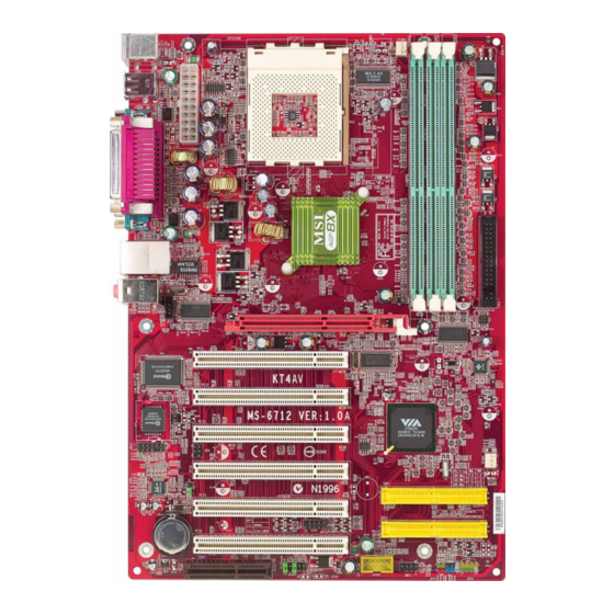
MS-6712 ATX Mainboard Mainboard Layout Top : mouse CFAN1 Bottom: keyboard SOCKET 462 ports Top : Parallel Port Bottom: COM A COM B KT400A T: LAN jack B: USB ports T: MIC M: Line-In B: Line-Out AGP Slot VT6103 JCD1 PCI Sl ot 1 Winbond W83697HF... -
Page 12: Msi Special Features
Live Monitor™ The Live Monitor™ is a tool used to schedule the search for the latest BIOS/drivers version on the MSI Web site. To use the function, you need to install the “MSI Live Update 2” application. After the installation, the “MSI Live Monitor” icon (as shown on the right) will appear on the screen. -
Page 13: D-Bracket™ 2 (Optional)
MS-6712 ATX Mainboard D-Bracket™ 2 (Optional) D-Bracket™ 2 is a USB bracket integrating four Diagnostic LEDs, which use graphic signal display to help users understand their system. The LEDs provide up to 16 combinations of signals to debug the system. The 4 LEDs can detect all problems that fail the system, such as VGA, RAM or other failures. - Page 14 Getting Started Green D-Bracket™ 2 Description Processor Initialization - This will show information regarding the processor (like brand name, system bus, etc…) Testing RTC (Real Time Clock) Initializing Video Interface - This will start detecting CPU clock, checking type of video onboard.
-
Page 15: Msi Dvd 5.1 Channel (Optional)
To play DVD with 6-channel audio output, you must configure both the MSI DVD application and the audio codec’s software utility. Otherwise, the 6- channel audio function will not work properly. For information on how to select 6-channel mode in the audio software utility, refer to Appendix. - Page 16 Getting Started 4. Click OK. For more information about MSI DVD, you can refer to the online help coming with the application. To enter the online help: 1. Click on the icon at the bottom-right corner of the control panel.
-
Page 17: Live Bios™/Live Driver
BIOS/drivers online so that you don’t need to search for the correct BIOS/driver version throughout the Web site. To use the function, you need to install the “MSI Live Update 2” application. After the installation, the “MSI Live Update 2” icon (as shown on the right) will appear on the screen. -
Page 18: Cpu Thermal Protection
Getting Started CPU Thermal Protection Aimed to prevent the CPU from overheating, MSI has developed a CPU Thermal Protection mechanism for AMD Athlon™ XP CPU platform. This CPU Thermal Protection mechanism works on a thermal signal sensor. If the mechanism senses an abnormal temperature rise, it will automatically shut down the system and the CPU temperature will then drop down and resume normal. -
Page 19: Chapter 2. Hardware Setup
Hardware Setup Hardware Setup This chapter tells you how to install the CPU, memory modules, and expansion cards, as well as how to setup the jump- ers on the mainboard. Also, it provides the instructions on con- necting the peripheral devices, such as the mouse, keyboard, etc. -
Page 20: Quick Components Guide
MS-6712 ATX Mainboard Quick Components Guide JWR1, p.2-9 CPU, p.2-3 CFAN1, p.2-17 DDR DIMMs, p.2-7 Back Panel I/O, p.2-10 FDD1, p.2-15 JCD1, p.2-25 AGP Slot, p.2-27 PCI Slots, p.2-27 JCI1, p.2-24 JSP3, p.2-22 JIR1, p.2-24 SFAN1, p.2-17 JBAT1, p.2-26 IDE1 IDE2, p.2-16 JFP1 &... -
Page 21: Central Processing Unit: Cpu
Hardware Setup Central Processing Unit: CPU ® The mainboard supports AMD Athlon™, Athlon™ XP and Duron™ processors in the 462 pin package. The mainboard uses a CPU socket called Socket A for easy CPU installation. When you are installing the CPU, make sure the CPU has a heat sink and a cooling fan attached on the top to prevent overheating. -
Page 22: Cpu Installation Procedures For Socket 462
MS-6712 ATX Mainboard CPU Installation Procedures for Socket 462 Please turn off the power and unplug the power cord before Open Lever installing the CPU. Sliding Pull the lever sideways away 90 degree Plate from the socket. Make sure to raise the lever up to a 90- degree angle. -
Page 23: Installing Amd Athlon Cpu (Socket 462) Cooler Set
4. Connect the fan to the power sup- ply connector provided on your mainboard. MSI Reminds You... Please apply some heat sink paste on top of your CPU to dissipate the heat more effectively. -
Page 24: Cpu Clock Frequency Selection Through Bios
BIOS setup utility. To set the clock frequency for the installed CPU, refer to Frequency/ Voltage Control in Chapter 3. BIOS Setup. MSI Reminds You... Overheating Overheating will seriously damage the CPU and system, al- ways make sure the cooling fan can work properly to protect the CPU from overheating. -
Page 25: Memory
Hardware Setup Memory The mainboard provides 3 slots for 184-pin DDR SDRAM DIMM (Double In-Line Memory Module) modules and supports the memory size up to 3GB. You can install PC3200/DDR400, PC2700/DDR333, PC2100/ DDR266 or PC1600/DDR200 modules on the DDR DIMM slots. Please note that the mainboard supports only one DDR400 DIMM. -
Page 26: Dimm Module Combination
3. The plastic clip at each side of the DIMM slot will automatically close. Notch Volt MSI Reminds You... You can barely see the golden finger if the module is properly inserted in the socket. -
Page 27: Power Supply
Hardware Setup Power Supply The mainboard supports ATX power supply for the power system. Be- fore inserting the power supply connector, always make sure that all compo- nents are installed properly to ensure that no damage will be caused. ATX 20-Pin Power Connector: JWR1 This connector allows you to connect to an ATX power supply. -
Page 28: Back Panel
MS-6712 ATX Mainboard Back Panel The back panel provides the following connectors: Parallel (Optional) Mouse L-in L-out Keyboard COM A COM B Mouse Connector The mainboard provides a standard PS/2 ® mouse mini DIN connector ® ® for attaching a PS/2 mouse. -
Page 29: Keyboard Connector
Hardware Setup Keyboard Connector ® The mainboard provides a standard PS/2 keyboard mini DIN connec- ® ® tor for attaching a PS/2 keyboard. You can plug a PS/2 keyboard directly into this connector. Pin Definition SIGNAL DESCRIPTION Keyboard DATA Keyboard DATA No connection Ground Keyboard Clock... -
Page 30: Parallel Port Connector: Lpt1
MS-6712 ATX Mainboard Parallel Port Connector: LPT1 The mainboard provides a 25-pin female centronic connector as LPT. A parallel port is a standard printer port that supports Enhanced Parallel Port (EPP) and Extended Capabilities Parallel Port (ECP) mode. Pin Definition SIGNAL DESCRIPTION STROBE... -
Page 31: Audio Port Connectors
1/8” Stereo Audio Connectors Line In Line Out MSI Reminds You... For advanced audio application, RealTek ALC650 audio chip is provided as an option to offer support for 6-channel audio operation and can turn rear audio connectors from 2-channel to 4-/6-channel audio. -
Page 32: Serial Port Connectors: Com A & Com B
MS-6712 ATX Mainboard Serial Port Connectors: COM A & COM B The mainboard offers two 9-pin male DIN connectors as serial port COM A & COM B. The ports are 16550A high speed communication ports that send/receive 16 bytes FIFOs. You can attach a serial mouse or other serial devices directly to the connectors. -
Page 33: Connectors
Hardware Setup Connectors The mainboard provides connectors to connect to FDD, IDE HDD, case, modem, LAN, USB Ports, IR module and CPU/System FAN. Floppy Disk Drive Connector: FDD1 The mainboard provides a standard floppy disk drive connector that supports 360K, 720K, 1.2M, 1.44M and 2.88M floppy disk types. FDD1 2-15... -
Page 34: Hard Disk Connectors: Ide1 & Ide2
IDE2 (Secondary IDE Connector) IDE2 can also connect a Master and a Slave drive. MSI Reminds You... If you install two hard disks on cable, you must configure the second drive to Slave mode by setting its jumper. Refer to the hard disk documentation supplied by hard disk vendors for jumper setting instructions. -
Page 35: Fan Power Connectors: Cfan1/Sfan1
+12V SENSOR +12V SFAN1 MSI Reminds You... 1. Always consult the vendors for proper CPU cooling fan. 2. CPUFAN supports the fan control. You can install the PC Alert utility that will automatically control the CPU fan speed according to the actual CPU temperature. -
Page 36: Front Panel Connectors: Jfp1 & Jfp2
MS-6712 ATX Mainboard Front Panel Connectors: JFP1 & JFP2 The mainboard provides two front panel connectors for electrical con- ® nection to the front panel switches and LEDs. JFP1 is compliant with Intel Front Panel I/O Connectivity Design Guide. Power Power Speaker Switch... -
Page 37: Front Panel Audio Connector: Jaud1
Left channel audio signal to front panel AUD_RET_L Left channel audio signal return from front panel MSI Reminds You... If you don’t want to connect to the front audio header, pins 5 & 6, 9 & 10 have to be jumpered in order to have signal output directed to the rear audio ports. -
Page 38: Front Usb Connector: Jusb1
(USB 1.1/Intel spec) USB0+ USB1+ USBOC MSI Reminds You... The USB 2.0 technology is downward compatible with USB 1.1 spec. To use the USB 2.0 ports, you have to install the USB 2.0 ® driver, which is supplied by Microsoft for Windows 2000 and XP. -
Page 39: D-Bracket™ 2 Connector: Jled1
Hardware Setup D-Bracket™ 2 Connector: JLED1 The mainboard comes with a JLED1 connector for you to connect to D- Bracket™ 2. D-Bracket™ 2 is a USB Bracket that supports both USB1.1 & 2. 0 spec. It integrates four LEDs and allows users to identify system problem through 16 various combinations of LED signals. -
Page 40: S-Bracket Connector: Jsp3
MS-6712 ATX Mainboard S-Bracket Connector: JSP3 The connector allows you to connect a S-Bracket for Sony & Philips Digital Interface (SPDIF). The S-Bracket offers 2 SPDIF jacks for digital audio transmission (one for optical fiber connection and the other for coaxial), and 2 analog Line-Out jacks for 4-channel audio output. - Page 41 Hardware Setup Optional S-Bracket CEN/SUB RL/RR Connect to JSP3 SPDIFJack (optical) SPDIF Jack (coaxial) Analog Line-Out Jacks 2-23...
-
Page 42: Irda Infrared Module Header: Jir1
MS-6712 ATX Mainboard IrDA Infrared Module Header: JIR1 The connector allows you to connect to IrDA Infrared module. You must configure the setting through the BIOS setup to use the IR function. ® JIR1 is compliant with Intel Front Panel I/O Connectivity Design Guide. JIR1 Pin Definition Signal VCC5... -
Page 43: Cd-In Connector: Jcd1
Hardware Setup CD-In Connector: JCD1 The connector is for CD-ROM audio connector. JCD1 2-25... -
Page 44: Jumpers
Keep Data Clear Data JBAT1 MSI Reminds You... You can clear CMOS by shorting 2-3 pin while the system is off. Then return to 1-2 pin position. Avoid clearing the CMOS while the system is on; it will damage the mainboard. -
Page 45: Slots
Hardware Setup Slots The motherboard provides one AGP slot, six 32-bit PCI bus slots, and one CNR slot. AGP Slot PCI Slots CNR Slot AGP (Accelerated Graphics Port) Slot The AGP slot allows you to insert the AGP graphics card. AGP is an interface specification designed for the throughput demands of 3D graphics. -
Page 46: Pci Interrupt Request Routing
MS-6712 ATX Mainboard PCI Interrupt Request Routing The IRQ, acronym of interrupt request line and pronounced I-R-Q, are hardware lines over which devices can send interrupt signals to the microprocessor. The PCI IRQ pins are typically connected to the PCI bus INT A# ~ INT D# pins as follows: Order 1 Order 2... -
Page 47: Chapter 3. Bios Setup
BIOS Setup BIOS Setup This chapter provides information on the BIOS Setup program and allows you to configure the system for optimum use. You may need to run the Setup program when: An error message appears on the screen during the system booting up, and requests you to run SETUP. -
Page 48: Entering Setup
MS-6712 ATX Mainboard Entering Setup Power on the computer and the system will start POST (Power On Self Test) process. When the message below appears on the screen, press <DEL> key to enter Setup. DEL:Setup F11:Boot Menu F12:Network boot TAB:Logo If the message disappears before you respond and you still wish to enter Setup, restart the system by turning it OFF and On or pressing the RESET button. -
Page 49: Control Keys
BIOS Setup Control Keys < > Move to the previous item < > Move to the next item < > Move to the item on the left-hand side < > Move to the item on the right-hand side <Enter> Select the item <Esc>... -
Page 50: The Main Menu
MS-6712 ATX Mainboard The Main Menu Once you enter AMIBIOS NEW SETUP UTILITY, the Main Menu will ap- pear on the screen. The Main Menu displays twelve configurable functions and two exit choices. Use arrow keys to move among the items and press <Enter>... - Page 51 BIOS Setup Integrated Peripherals Use this menu to specify your settings for integrated peripherals. PC Health Status This entry shows your PC health status. Frequency/Voltage Control Use this menu to specify your settings for frequency/voltage control. Set Supervisor Password Use this menu to set Supervisor Password. Set User Password Use this menu to set User Password.
-
Page 52: Standard Cmos Features
MS-6712 ATX Mainboard Standard CMOS Features The items inside STANDARD CMOS FEATURES menu are divided into 9 categories. Each category includes none, one or more setup items. Use the arrow keys to highlight the item you want to modify and use the <PgUp> or <PgDn>... - Page 53 When Enabled, BIOS will issue a virus warning message and beep if a write to the boot sector or the partition table of the HDD is attempted. Setting options: Disabled and Enabled. MSI Reminds You... This feature only protects the boot sector, not the whole hard disk.
-
Page 54: Advanced Bios Features
MS-6712 ATX Mainboard Advanced BIOS Features Quick Boot Setting the item to Enabled allows the system to boot within 5 seconds since it will skip some check items. Available options: Enabled, Disabled. Full Screen Logo Show This item enables you to show the company logo on the bootup screen. Set- tings are: Enabled Shows a still image (logo) on the full screen at boot. - Page 55 BIOS Setup IDE-2 The system will boot from the third HDD. IDE-3 The system will boot from the fourth HDD. Floppy The system will boot from floppy drive. ARMD-FDD The system will boot from any ARMD device, such as LS-120 or ZIP drive, that functions as a floppy drive. ARMD-HDD The system will boot from ARMD device, such as MO or ZIP drive, that functions as hard disk drive.
- Page 56 MO or ZIP drive, that functions as hard disk drive. Disabled Disable this sequence. MSI Reminds You... 1. Available settings for “1st/2nd/3rd Boot Device” vary de- pending on the bootable devices you have installed. For example, if you did not install a floppy drive, the setting “Floppy”...
- Page 57 BIOS Setup Primary Display This configures the primary subsystem in the computer. Available options: Mono (monochrome), CGA40x25, CGA80x25, VGA/EGA, Absent. Password Check This specifies the type of AMIBIOS password protection that is implemented. Setting options are described below. Option Description Setup The password prompt appears only when end users try to run Setup.
- Page 58 MS-6712 ATX Mainboard Option Description Disabled The specified ROM is not copied to RAM. Enabled The contents of specified ROM are copied to RAM for faster system performance. Cached The contents of specified ROM are not only copied to RAM, the contents of the ROM area can be writ- ten to and read from cache memory.
-
Page 59: Advanced Chipset Features
BIOS Setup Advanced Chipset Features MSI Reminds You... Change these settings only if you are familiar with the chipset. DRAM Timing Control Press <Enter> and the following sub-menu appears. Current Host Clock This item shows the current CPU frequency. Configure SDRAM Timing by Selects whether DRAM timing is controlled by the SPD (Serial Presence Detect) EEPROM on the DRAM module. - Page 60 MS-6712 ATX Mainboard SDRAM Frequency, SDRAM CAS# Latency, Row Precharge Time, RAS Pulse Width, RAS to CAS Delay and SDRAM Bank Interleave auto- matically to be determined by BIOS based on the configurations on the SPD. Selecting User allows users to configure these fields manually. SDRAM Frequency Use this item to configure the clock frequency of the installed SDRAM.
- Page 61 BIOS Setup Disable the function if 16MB SDRAM is installed. Settings: Disabled, 2-Way and 4-Way. DDR400 tWRT Timing This controls the timing delay (in clock cycles) before DDR400 starts a write command after receiving it. Settings: 1T, 2T, 3T. 3T increases the delay time while 1T provides the least timing delay.
- Page 62 MS-6712 ATX Mainboard AGP Timing Control Press <Enter> and the following sub-menu appears. AGP Mode The item sets an appropriate mode for the installed AGP card. Set- ting options: 1x, 2x, 4x, Auto. Select 4x only if your AGP card sup- ports it.
- Page 63 BIOS Setup PCI Delay Transaction The chipset has an embedded 32-bit posted write buffer to support delayed transactions cycles so that transactions to and from the ISA bus are buffered and PCI bus can perform other transactions while the ISA transaction is underway.
-
Page 64: Power Management Features
MS-6712 ATX Mainboard Power Management Features MSI Reminds You... S3-related functions described in this section are available only when your BIOS supports S3 sleep mode. ACPI Standby State This item secifies the power saving modes for ACPI function. If your operating... - Page 65 BIOS Setup when system wakes up (resumes) from S3 sleep state. The system resume time is shortened when you disable the function, but system will need an AGP driver to initialize the VGA card. Therefore, if the AGP driver of the card does not support the initialization feature, the display may work abnormally or not function after resuming from S3.
- Page 66 MS-6712 ATX Mainboard CPU HALT Command Detection This item allows your OS to determine whether the CPU will enter the HALT command state. Options: Enabled, Disabled. Power Button Function This feature sets the function of the power button. Settings are: On/Off The power button functions as normal power off button.
- Page 67 00 ~ 23 Alarm Minute 00 ~ 59 Alarm Second 00 ~ 59 MSI Reminds You... If you have changed this setting, you must let the system boot up until it enters the operating system, before this function will work. 3-21...
-
Page 68: Pnp/Pci Configurations
MS-6712 ATX Mainboard PNP/PCI Configurations This section describes configuring the PCI bus system and PnP (Plug & Play) feature. PCI, or Peripheral Component Interconnect, is a system which al- lows I/O devices to operate at speeds nearing the speed the CPU itself uses when communicating with its special components. - Page 69 BIOS Setup PCI Latency Timer This item controls how long each PCI device can hold the bus before another takes over. When set to higher values, every PCI device can conduct transac- tions for a longer time and thus improve the effective PCI bandwidth. For better PCI performance, you should set the item to higher values.
-
Page 70: Integrated Peripherals
MS-6712 ATX Mainboard Integrated Peripherals Floppy Disk Controller This is used to enable or disable the onboard Floppy controller. Option Description Auto BIOS will automatically determine whether to enable the onboard Floppy controller or not. Enabled Enables the onboard Floppy controller. Disabled Disables the onboard Floppy controller. - Page 71 BIOS Setup IR Pin Select Set to IRRX/IRTX when using an internal IR module connected to the IR header. Set to SINB/SOUTB. when connecting an IR adapter to COM B. Parallel Port This field specifies the base I/O port address of the onboard parallel port. Selecting Auto allows AMIBIOS to automatically determine the correct base I/O port address.
- Page 72 MS-6712 ATX Mainboard AC’97 Audio Auto allows the mainboard to detect whether an audio device is used. If an audio device is detected, the onboard AC’97 (Audio Codec’97) controller will be enabled; if not, it is disabled. Disable the controller if you want to use other controller cards to connect an audio device.
-
Page 73: Pc Health Status
BIOS Setup PC Health Status This section shows the status of your CPU, fan, overall system status, etc. Monitor function is available only if there is hardware monitoring mechanism onboard. Chassis Intrusion The field enables or disables the feature of recording the chassis intrusion status and issuing a warning message if the chassis is once opened. -
Page 74: Frequency/Voltage Control
MS-6712 ATX Mainboard Frequency/Voltage Control Use this menu to specify your settings for frequency/voltage control. Spread Spectrum When the motherboard’s clock generator pulses, the extreme values (spikes) of the pulses creates EMI (Electromagnetic Interference). The Spread Spec- trum function reduces the EMI generated by modulating the pulses so that the spikes of the pulses are reduced to flatter curves. - Page 75 BIOS Setup MSI Reminds You... Changing CPU Ratio/Vcore could result in the instability of the system; therefore, it is NOT recommended to change the default setting for long-term usage. DDR Voltage (V) Adjusting the DDR voltage can increase the DDR speed. Any changes made to this setting may cause a stability issue, so changing the DDR voltage for long-term purpose is NOT recommended.
-
Page 76: Set Supervisor/User Password
BIOS FEATURES menu. If the PASSWORD CHECK option is set to Always, the password is required both at boot and at entry to Setup. If set to Setup, password prompt only occurs when you try to enter Setup. MSI Reminds You... About Supervisor Password & User Password: Supervisor password: Can enter and change the settings of the setup menu. -
Page 77: Load High Performance/Bios Setup Defaults
Pressing ‘Enter’ loads the default BIOS values that enable the best system performance but may lead to a stability issue. MSI Reminds You... The option is for power or overclocking users only. Use of high performance defaults will tighten most timings to increase the system performance. -
Page 78: Appendix: Using 4- Or 6-Channel Audio Function
Using 4- or 6-Channel Audio Function Appendix: Using 4- or 6-Channel Audio Function The motherboard is equipped with Realtek ALC650 chip, which pro- vides support for 6-channel audio output, including 2 Front, 2 Rear, 1 Center and 1 Subwoofer channel. ALC650 allows the board to attach 4 or 6 speakers for better surround sound effect. -
Page 79: Installing The Audio Driver
1. Insert the companion CD into the CD-ROM drive. The setup screen will automatically appear. 2. Click Avance ALC650 Sound Drivers. Click here MSI Reminds You... The AC97 Audio Configuration software utility is under con- tinuous update to enhance audio applications. Hence, the program screens shown here in this appendix may be slightly different from the latest software utility and shall be held for reference only. - Page 80 Using 4- or 6-Channel Audio Function 3. Click Next to start installing files into the system. Click here 4. Click Finish to restart the system. Select this option Click here...
-
Page 81: Using 4- Or 6-Channel Audio Function
MS-6712 ATX Mainboard Using 4- or 6-Channel Audio Function After installing the audio driver, you are able to use the 4-/6-channel audio feature now. To enable 4- or 6-channel audio operation, first connect 4 or 6 speakers to the appropriate audio connectors, and then select 4- or 6- channel audio setting in the software utility. - Page 82 Using 4- or 6-Channel Audio Function d. 6-Channel Mode for 5.1-Speaker Output 5. Select or clear the Default Phonejack check box to decide which audio devices you wish to use for audio outputs. The instructions shown on the Speaker Configuration screen may vary depending on how you set the options of No.
- Page 83 Coaxial SPDIF jack Coaxial SPDIF jack Back Panel S-Bracket MSI Reminds You... When any Multi-Channel Audio Mode is selected, you may also connect your speakers to the Optical or Coaxial SPDIF phonejack on the S-Bracket to exprience digital surround sound effect.
- Page 84 Using 4- or 6-Channel Audio Function 4-Channel Mode for 4-Speaker Output When this mode is selected, plug the two front speakers to the Line Out connector on the back panel, and the other two rear speakers to the Line Out connector on the S-Bracket. Refer to the following diagram and caption for the function of each phonejack on the back panel and S-Bracket when 4-Channel mode is selected.
- Page 85 Line Out (Rear channels) Back Panel S-Bracket MSI Reminds You... If the Center and Subwoofer speaker exchange their audio chan- nels when you play video or music on the computer, a converter may be required to exchange center and subwoofer audio...
- Page 86 S-Bracket. S-Bracket Optical SPDIF jack Coaxial SPDIF jack Plug MSI Reminds You... Some commonly-used audio output for- mats (midi, wav,..etc.) may not be able to be output from the SPDIF jacks of the S-Bracket. To convert these audio formats as SPDIF output: 1.
-
Page 87: Using The Back Panel Only
MS-6712 ATX Mainboard Using the Back Panel only In addition to a default 2-channel analog audio output function, the au- dio connectors on the Back Panel also provide 4- or 6-channel analog audio output function if a proper setting is made in the software utility. Read the following steps to have the Multi-Channel Audio Function properly set in the software utility, and have your speakers correctly con- nected to the Back Panel. - Page 88 Using 4- or 6-Channel Audio Function Connecting the Speakers When you have set the Multi-Channel Audio Function mode properly in the software utility, connect your speakers to the correct phonejacks in accordance with the setting in software utility. 2-Channel Mode for Stereo-Speaker Output Refer to the following diagram and caption for the function of each phonejack on the back panel when 2-Channel Mode is selected.
- Page 89 MS-6712 ATX Mainboard 4-Channel Mode for 4-Speaker Output The audio jacks on the back panel always provide 2-channel analog audio output function, however these audio jacks can be transformed to 4- or 6- channel analog audio jacks by selecting the corresponding multi-channel operation from No.
- Page 90 * Both Line In and MIC function are converted to Line Out function when 4- Channel Mode for 6-Speaker Output is selected. MSI Reminds You... If the Center and Subwoofer speaker exchange their audio chan- nels when you play video or music on the computer, a converter may be required to exchange center and subwoofer audio signals.
-
Page 91: Testing The Connected Speakers
Front Right Rear Right Rear Left Center MSI Reminds You... 6 speakers appear on the “Speaker Test” window only when you select “6-Channel Mode” in the “No. of Speakers” column. If you select “4-Channel Mode”, only 4 speakers appear on the window. - Page 92 Using 4- or 6-Channel Audio Function 4. While you are testing the speakers in 6-Channel Mode, if the sound com- ing from the center speaker and subwoofer is swapped, you should select Swap Center/Subwoofer Output to readjust these two channels. Select this function A-15...
-
Page 93: Playing Karaok
MS-6712 ATX Mainboard Playing KaraOK The KaraOK function will automatically remove human voice (lyrics) and leave melody for you to sing the song. Note that this function applies only for 2-channel audio operation. Playing KaraOK 1. Click the audio icon from the window tray at the lower-right corner of the screen. -
Page 94: Troubleshooting
Troubleshooting Troubleshooting Troubleshooting Q: How do I know that the product that I have is from MSI? All MSI product starts with the character MS-XXXX or Marketing Name (MS-XXXX) wherein XXXX refers to numbers. You should be able to find the Model number in between the PCI slots. - Page 95 If problem still persists, you would need to purchase new BIOS chip from Websites like www.flashbios.org where you can order a new BIOS or you can also contact MSI office near your place to purchase new BIOS chip http://www.msi.com.tw/html/contact/contact.htm Q: Why my motherboard BIOS sticker is "Phoenix BIOS" but when I boot up my system I saw that "Award BIOS"...
- Page 96 CPU type 3. For Optical product firmware, refer to http://www.msi.com.tw/pro- gram/support/driver/dvr/spt_dvr_list.php?part=4 Q: Where can I find MSI developed software such as Fuzzy Logic or PC Alert? Refer to http://www.msi.com.tw/program/support/software/swr/ spt_swr_list.php Q: Where can I find the manual? 1.
- Page 97 2. Try to clear the CMOS If problem still persists, ask your reseller for new BIOS chip or contact one of MSI office near your place for new BIOS chip http://www.msi.com.tw/contact/main.htm Q: Should I update my BIOS, once a new BIOS is released? 1.
- Page 98 4. For Optical product firmware, refer to http://www.msi.com.tw/pro- gram/support/driver/dvr/spt_dvr_list.php?part=4 5. For MSI special product like bluetooth or TV tuner, refer to http:// www.msi.com.tw/program/support/driver/dvr/spt_dvr_list.php?part=5 Q: How can I know what CPU can my motherboard support? 1. For Server motherboard, refer to http://www.msi.com.tw/program/ support/cpu_support/cpu/spt_cpu_list.php?kind=3...
- Page 99 Q: How can I find MSI distributor in my country? Refer to http://www.msi.com.tw/program/contact/where2buy/ Select the country & you will find MSI distributor in that country. If in case you cannot find the country listed, then it means MSI still don¡¦t have distributor...
- Page 100 Move the PCI card to different PCI slots Update the card BIOS or drivers Update the motherboard BIOS Q: What should I do if my MSI VGA card have compatibility issue with an- other brand of motherboard? Update the video driver...
-
Page 101: Glossary
Glossary Glossary Glossary ACPI (Advanced Configuration & Power Interface) This power management specification enables the OS (operating system) to control the amount of power given to each device attached to the computer. Windows 98/98SE, Windows 2000 and Windows ME can fully support ACPI to allow users managing the system power flexibly. - Page 102 MS-6712 ATX Mainboard contents of frequently accessed RAM locations and the addresses where these data items are stored. Chipset A collection of integrated chips designed to perform one or more related functions. For example, a modem chipset contains all the primary circuits for transmitting and receiv- ing data;...
- Page 103 Glossary ECC Memory (Error Correcting Code Memory) A type of memory that contains special circuitry for testing the accuracy of data and correcting the errors on the fly. EEPROM Acronym for Electrically Erasable Programmable Read-Only Memory. An EEPROM is a special type of PROM that can be erased by exposing it to an electrical charge. Like other types of PROM, EEPROM retains its contents even when the power is turned off.
- Page 104 MS-6712 ATX Mainboard IDE (Integrated Drive Electronics) A type of disk-drive interface widely used to connect hard disks, CD-ROMs and tape drives to a PC, in which the controller electronics is integrated into the drive itself, eliminating the need for a separate adapter card. The IDE interface is known as the ATA (AT Attachment) specification.
- Page 105 Glossary LBA (Logical Block Addressing) Logical block addressing is a technique that allows a computer to address a hard disk larger than 528 megabytes. A logical block address is a 28-bit value that maps to a specific cylinder-head-sector address on the disk. 28 bits allows sufficient variation to specify addresses on a hard disk up to 8.4 gigabytes in data storage capacity.
- Page 106 MS-6712 ATX Mainboard PS/2 Port A type of port developed by IBM for connecting a mouse or keyboard to a PC. The PS/2 port supports a mini DIN plug containing just 6 pins. Most modern PCs equipped with PS/2 ports so that the special port can be used by another device, such as a modem.
- Page 107 Demo Mode S3 Mode Reboot Shutdown PC3200¡ ] DDR400¡ ^ x 3 Play 12hr Looping 12hr 100 Times 100 Times 100 Times Samsung 256M (K4H560838D-TCC4) Please visit the MSI Web site for the latest update on Recommended DDR400 Modules.
- Page 108 MS-6712 ATX Mainboard MS-6712 V:1.0A Test item PC3200¡ ] DDR400¡ ^ x 2 Business Winstone 2001 Tmem Infineon 128M (HYS64D16301GU-5-B) HYB25D256160BT-5 Infineon 256M (HYS64D32300GU-5-B) HYB25D256800BT-5 MICRON 256M (MT16VDDT3264AG-403B4 US) MT46V16M8TG-5 ES B Winbond 256M (W9425GCDB-5) W942508CH-5 Winbond 256M (Kingston KVR400X64C25/256) W942508BH-5 SEC 256M (M368L3223DTM-CC4) K4H560838D-TCC4...
- Page 109 200 MHz YES* 266 MHz 333 MHz 400 MHz YES* : User may try this combination, but MSI will not guarantee its functionality. * : To know which DDR module is compatible with the mainboard, see Recom- mended DDR400 Modules.
Need help?
Do you have a question about the KT4A-V and is the answer not in the manual?
Questions and answers