Table of Contents
Advertisement
Advertisement
Table of Contents

Related Manuals for MSI 865PE Neo3-F


Summary of Contents for MSI 865PE Neo3-F
- Page 1 865PE/G Neo3 MS-6728 (v3.X) ATX Mainboard G52-M6728XX...
-
Page 2: Fcc-B Radio Frequency Interference Statement
Manual Rev: 3.1 Release Date: October 2004 FCC-B Radio Frequency Interference Statement This equipment has been tested and found to comply with the limits for a class B digital device, pursuant to part 15 of the FCC rules. These limits are designed to provide reasonable protection against harmful interference when the equipment is operated in a commercial environment. -
Page 3: Copyright Notice
Copyright Notice The material in this document is the intellectual property of MICRO-STAR INTERNATIONAL. We take every care in the preparation of this document, but no guarantee is given as to the correctness of its contents. Our products are under continual improvement and we reserve the right to make changes without notice. -
Page 4: Safety Instructions
Alternatively, please try the following help resources for further guidance. Visit the MSI homepage & FAQ site for technical guide, BIOS updates, driver updates, and other information: http://www.msi.com.tw & http://www.msi. -
Page 5: Table Of Contents
CONTENTS FCC-B Radio Frequency Interference Statement ............ii Copyright Notice ......................iii Revision History ......................iii Safety Instructions ...................... iv Technical Support ......................iv English version ....................E-1-1 1. Getting Started .................... E-1-3 2. Hardware Setup ..................E-2-1 3. BIOS Setup ....................E-3-1 4. - Page 6 Getting Started 865PE/G Neo3 User’s Guide English E-1-1...
- Page 7 MS-6728 ATX Mainboard E-1-2...
-
Page 8: Getting Started
Getting Started Chapter 1. Getting Started Getting Started Thank you for choosing the 865PE/G Neo3 (MS-6728) v3.X ATX mainboard. The 865PE/G Neo3 is based on Intel ® 865PE/G & ICH5/5R chipsets for optimal system efficiency. Designed to fit the advanced Intel ®... -
Page 9: Mainboard Specifications
Pentium 4 Prescott LGA775 processors in LGA775 package. Supports up to Pentium 4 3XX, 5XX, 6XX & P4EE (Intel Pentium 4 Processor with HT Technology Extreme Edition) sequence processor or higher speed. (For the latest information about CPU, please visit http://www.msi.com.tw/program/ products/mainboard/mbd/pro_mbd_cpu_support.php) Chipset Intel ®... - Page 10 Getting Started On-Board Peripherals On-Board Peripherals include: - 1 floppy port supports 1 FDD with 360K, 720K, 1.2M, 1.44M and 2.88Mbytes - 1 serial port COMA - 1 VGA port (for 865G only) - 1 parallel port supports SPP/EPP/ECP mode - 8 USB 2.0 ports (Rear * 4/ Front * 4) - 1 Line-In / Line-Out / Mic-In / Real Speaker Out / Center-Subwoofer Speaker Out / SPDIF Out-Optical audio port...
-
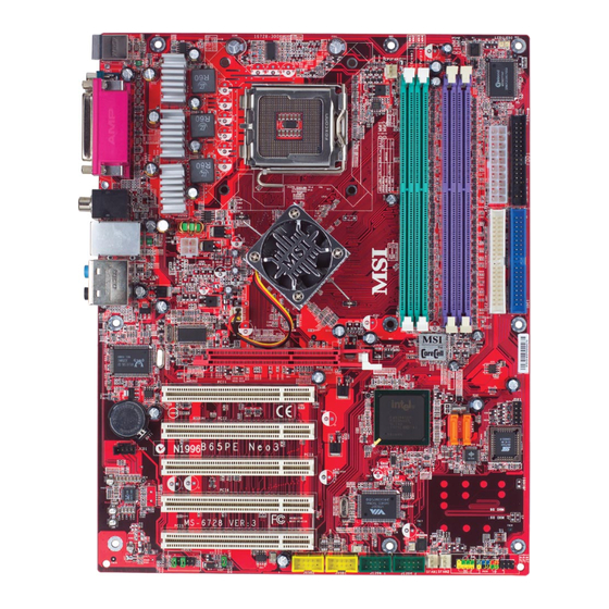
Page 11: Mainboard Layout
MS-6728 ATX Mainboard Mainboard Layout Top : mouse JCI1 CPUFAN1 Bottom: keyboard Winbond W83627HF Top : Parallel Port Bottom: COM A VGA Port (Optional) T: SPDIF Out B: USB ports JPW1 T: LAN jack (Optional) B: USB ports Intel 865PE/G Line-In Line-Out T:RS-Out... -
Page 12: Hardware Setup
Hardware Setup Chapter 2. Hardware Setup Hardware Setup This chapter tells you how to install the CPU, memory modules, and expansion cards, as well as how to setup the jumpers on the mainboard. Also, it provides the instructions on connecting the peripheral devices, such as the mouse, keyboard, etc. -
Page 13: Quick Components Guide
MS-6728 ATX Mainboard Quick Components Guide CPUFAN1, p.2-15 CPU, p.2-3 DDR DIMMs, p.2-7 JCI1, p.2-23 ATX1, p.2-9 Back Panel I/O, p.2-10 FDD1, p.2-14 JPW1, p.2-9 NBFAN1,p.2-15 IDE1, IDE2, p.2-16 AGP Slot, p.2-26 JDB1, p.2-19 BATT SATA1, SATA2, JCD1, p.2-24 BIOS p.2-17 PCI Slots, p.2-26... -
Page 14: Introduction To Lga 775 Cpu
If you do not have the CPU cooler, contact your dealer to purchase and install them before turning on the computer. For the latest information about CPU, please visit http://www.msi.com.tw/ program/products/mainboard/mbd/pro_mbd_cpu_support.php. MSI Reminds You... -
Page 15: Cpu & Cooler Installation
4 fingers to push the CPU Clip down to clip them (the CPU clip is up and the CPU is down) together. MSI Reminds You... 1. Confirm if your CPU cooler is firmly installed before turning on your system. 2. Do not touch the CPU socket pins to avoid damaging. - Page 16 Hardware Setup 5. The CPU has a plastic cap on it to 6. Remove the cap from lever hinge side protect the contact from damage. (as the arrow shows). Before you have installed the CPU, always cover it to protect the socket pin.
- Page 17 MSI Reminds You... 1. Check the information in PC Health Status in BIOS (refer to p.3-25 for details) for the CPU temperature. 2. Whenever CPU is not installed, always protect your CPU socket pin with the plastic cap covered (shown in Figure 1) to avoid damaging.
-
Page 18: Introduction To Ddr Sdram
Hardware Setup Memory The mainboard provides 4 slots for 184-pin, 2.5V DDR DIMM with 8 memory banks. You can install DDR266 / DDR333 / DDR400 / DDR433 / DDR466 / DDR500 / DDR533 SDRAM modules on the DDR DIMM slots (DIMM 1~4). To operate properly, at least one DIMM module must be installed. - Page 19 128MB~1GB 128MB~1GB 128MB~1GB 512MB~4GB MSI Reminds You... Dual-channel DDR works ONLY in the 3 combinations listed in the table above. Installing DDR Modules 1. The DDR DIMM has only one notch on the center of module. The module will only fit in the right orientation.
-
Page 20: Power Supply
JPW1 Pin Definition JPW1 SIGNAL MSI Reminds You... 1. These two connectors connect to the ATX power supply and have to work together to ensure stable operation of the mainboard. 2. Power supply of 350 watts (and above) is highly recommended for system stability. -
Page 21: Back Panel
MS-6728 ATX Mainboard Back Panel The back panel provides the following connectors: RS-Out L-In Parallel S/PDIF Mouse VGA port USB Ports CS-Out COM A L-Out Keyboard (Optional) SPDIF Out Mouse/Keyboard Connector ® The mainboard provides a standard PS/2 mouse/keyboard mini DIN connec- ®... -
Page 22: Usb Connectors
Hardware Setup VGA Connector (Optional, for 865G only) The mainboard provides a DB 15-pin female connector to connect a VGA monitor. Signal Description Pin Signal Description GREEN BLUE VGA Connector Horizontal Sync Vertical Sync (DB 15-pin) USB Connectors The mainboard provides an OHCI (Open Host Controller Interface) Universal Serial Bus root for attaching USB devices such as keyboard, mouse or other USB- compatible devices. -
Page 23: Serial Port Connector
(in 7.1CH / 5.1CH) Center/Subwoofer Line Out Speaker Out ( in 7.1CH / 5.1CH) S/PDIF Out-Optical MSI Reminds You... For the advanced functions of the audio codec, please refer to Chapter 6: Introduction to RealTek ALC850 Audio Codec for details. E-2-12... - Page 24 Hardware Setup RJ-45 LAN Jack: 10/100 LAN (8100C) /Giga-bit LAN (8110S) (Optional) The mainboard provides two standard RJ-45 jacks for connection to Local Area Network (LAN). Giga-bit LAN enables data to be transferred at 1000, 100 or 10Mbps. You can connect a network cable to either LAN jack. Activity Indicator Link Indicator RJ-45 LAN Jack...
- Page 25 MS-6728 ATX Mainboard Parallel Port Connector: LPT1 The mainboard provides a 25-pin female centronic connector as LPT. A parallel port is a standard printer port that supports Enhanced Parallel Port (EPP) and Extended Capabilities Parallel Port (ECP) mode. Pin Definition SIGNAL DESCRIPTION STROBE...
- Page 26 Sensor Control SFAN1, SFAN2 NBFAN1 CPUFAN1 MSI Reminds You... 1. Always consult the vendors for proper CPU cooling fan. 2. CPUFAN1 supports the fan control. Fan/heatsink with 3 or 4 pins are both available. ® 3. Please refer to the recommended CPU fans at Intel official website.
- Page 27 IDE2 (Secondary IDE Connector) IDE2 can also connect a Master and a Slave drive. MSI Reminds You... If you install two hard disks on cable, you must configure the second drive to Slave mode by setting its jumper. Refer to the hard disk docu- mentation supplied by hard disk vendors for jumper setting instructions.
- Page 28 Take out the dust cover and connect to the hard disk devices Connect to serial ATA ports MSI Reminds You... Please do not fold the serial ATA cable in a 90-degree angle, for this might cause the loss of data during the transmission. E-2-17...
-
Page 29: Front Panel Connectors
MS-6728 ATX Mainboard Front Panel Connectors: JFP1 & JFP2 The mainboard provides two front panel connectors for electrical connection ® to the front panel switches and LEDs. JFP1 is compliant with Intel Front Panel I/O Connectivity Design Guide. Power Reset Switch JFP2 JFP1... - Page 30 Hardware Setup D-Bracket™ 2 Connector: JDB1 The mainboard comes with a JDB1 connector for you to connect to D- Bracket™ 2, which supports both USB 1.1 & 2.0 spec. D-Bracket™ 2 is a USB bracket integrating four Diagnostic LEDs, which use graphic signal display to help users understand their system.
- Page 31 MS-6728 ATX Mainboard D-Bracket™ 2 Green D-Bracket™ 2 Description System Power ON - The D-LED will hang here if the processor is damaged or not installed properly. Early Chipset Initialization Memory Detection Test - Testing onboard memory size. The D-LED will hang if the memory module is damaged or not installed properly.
- Page 32 Hardware Setup D-Bracket™ 2 Description Processor Initialization - This will show information regarding the processor (like brand name, system bus, etc…) Testing RTC (Real Time Clock) Initializing Video Interface - This will start detecting CPU clock, checking type of video onboard.
- Page 33 MS-6728 ATX Mainboard IEEE 1394 Connectors: J1394_1, J1394_2 (Optional) The mainboard provides two 1394 pin headers that allow you to connect IEEE 1394 ports via an external IEEE1394 bracket. Pin Definition SIGNAL SIGNAL TPA+ TPA- Ground Ground TPB+ TPB- J1394_1, J394_2 Cable power Cable power Key (no pin)
- Page 34 Left channel audio signal to front panel AUD_RET_L Left channel audio signal return from front panel MSI Reminds You... If you don’t want to connect to the front audio header, pins 5 & 6, 9 & 10 have to be jumpered in order to have signal output directed to the rear audio ports.
- Page 35 JUSB1 & JUSB2 Pin Definition SIGNAL SIGNAL USB0- USB1- JUSB2, JUSB1 USB0+ USB1+ (USB 2.0/Intel spec) Key (no pin) USBOC MSI Reminds You... Note that the pins of VCC and GND must be connected correctly or it may cause some damage. E-2-24...
-
Page 36: Clear Cmos Jumper Jbat1
JBAT1 Keep Data Clear Data MSI Reminds You... You can clear CMOS by shorting 2-3 pin while the system is off. Then return to 1-2 pin position. Avoid clearing the CMOS while the system is on; it will damage the mainboard. -
Page 37: Pci Interrupt Request Routing
MS-6728 ATX Mainboard Slots The mainboard provides one AGP slot and five 32-bit PCI bus slots. AGP (Accelerated Graphics Port) Slot The AGP slot allows you to insert the AGP graphics card. AGP is an interface specification designed for the throughput demands of 3D graphics. It introduces a 66MHz, 32-bit channel for the graphics controller to directly access main memory. -
Page 38: Bios Setup
SETUP. You want to change the default settings for customized features. MSI Reminds You... 1. The items under each BIOS category described in this chapter are under continuous update for better system performance. Therefore, the description may be slightly different from the latest BIOS and should be held for reference only. -
Page 39: Entering Setup
MS-6728 ATX Mainboard Entering Setup Power on the computer and the system will start POST (Power On Self Test) process. When the message below appears on the screen, press <DEL> key to enter Setup. DEL: Setup Menu TAB: Logo F11: Boot Menu F10: Flash Recovery If the message disappears before you respond and you still wish to enter Setup, restart the system by turning it OFF and On or pressing the RESET button. -
Page 40: The Main Menu
BIOS Setup The Main Menu Once you enter AMIBIOS NEW SETUP UTILITY, the Main Menu will appear on the screen. The Main Menu displays some main functions and two exit choices. Use arrow keys to move among the items and press <Enter> to enter the sub-menu. Standard CMOS Features Use this menu for basic system configurations, such as time, date etc. - Page 41 MS-6728 ATX Mainboard PC Health Status This entry shows your PC health status. Frequency/Voltage Control Use this menu to specify your settings for frequency/voltage control. Set Supervisor Password Use this menu to set Supervisor Password. Set User Password Use this menu to set User Password. Load High Performance Defaults Use this menu to load the BIOS values for the best system performance, but the system stability may be affected.
- Page 42 Performance Mode This item allows you to control the MAT (memory acceleration technology) function of CPU. MAT is MSI ’s exclusive technology, specializing in optimizing the data transfer rate among CPU, north bridge chip and memory, and also in procuring better memory performance and bandwidth up to 10%.
- Page 43 MS-6728 ATX Mainboard D.O.T. Range (D.O.T) Dynamic Overclocking Technology is the automatic overclocking function, included in the MSI ’s newly developed CoreCell Technology. It is designed to detect the load balance of CPU while running programs, and to adjust the best CPU frequency automatically.
- Page 44 AGP voltage is adjustable in the field, allowing you to increase the performance of your AGP display card when overclocking, but the stability may be affected. MSI Reminds You... The settings shown in different color in CPU Voltage (V), DDR Power Voltage and AGP Power Voltage helps to verify if your setting is proper for your system.
- Page 45 If the PASSWORD CHECK option is set to [Always], the password is required both at boot and at entry to Setup. If set to [Setup], password prompt only occurs when you try to enter Setup. MSI Reminds You... About Supervisor Password & User Password: Supervisor password: Can enter and change the settings of the setup menu.
- Page 46 Pressing ‘Enter’ loads the default BIOS values that enable the best system perfor- mance but may lead to a stability issue. MSI Reminds You... The option is for power or overclocking users only. Use of high performance defaults will tighten most timings to increase the system performance.
-
Page 47: Introduction To Digicell
Chapter 2. Hardware Setup Introduction to DigiCell DigiCell, the most useful and powerful utility that MSI has spent much research and efforts to develop, helps users to monitor and configure all the integrated peripherals of the system, such as audio program, power management, MP3 files management and communication / 802.11g WLAN... - Page 48 Introduction: Click on each icon appearing above to enter the sub-menu to make further configuration. Click on this button to link to MSI website: http://www.msi.com.tw. Quick Guide Click on this button and the quick guide of DigiCell will be displayed for you to review.
- Page 49 Power on Agent In this sub-menu, you can configure date, time and auto-executed programs of the power-on, power-off and restarting features. MSI Reminds You... Click on back button in every sub-menu and it will bring you back to the main menu.
- Page 50 In the H/W Diagnostic sub-menu, you can see the information, status and note of each DigiCell. You may double check the connection and installation of the item marked as gray. You may also click on the Mail to MSI button to send your questions or suggestions to MSI’s technical support staff. E-4-4...
- Page 51 Introduction to DigiCell Communication In the Communication sub-menu, you can see the status of all the LAN / WLAN / Bluetooth on the screen if the hardware is installed. The first icon indicates the onboard LAN on your system, the second icon indicates the wireless LAN status, and the third one is the information about the bluetooth on your system.
-
Page 52: Software Access Point
MS-6728 ATX Mainboard MSI Feature Software Access Point In the Software Access Point sub-menu, you can see the communication status on your system and choose the desired software access point mode by clicking on the desired icon, in which the default settings are configured for your usage. The default software access point mode is set to WLAN Card Mode. -
Page 53: Access Point Mode
Introduction to DigiCell Access Point Mode Click on “Setting” button of the Access Point Mode and the following screen will display. IP Sharing Click on this icon to enable/disable the IP sharing. The default of this setting is disabled. Disabled. Enabled. -
Page 54: Wlan Card Mode
MS-6728 ATX Mainboard MSI Feature enable this feature, only PCs with MAC address located in Association Control List can connect to the wireless LAN. MAC Address MAC stands for Media Access Control. A MAC address is the hardware address of a device connected to a network. -
Page 55: Live Update
BIOS/VGA Driver/OSD/Utility online so that you don’t need to search for the correct BIOS/driver version throughout the whole Web site. To use the function, you need to install the “MSI Live Update 3” application. After the installation, the “MSI Live Update 3”... -
Page 56: Mega Stick
MS-6728 ATX Mainboard MSI Feature MEGA STICK In the MEGA STICK sub-menu, you can configure the settings of MSI MEGA STICK and the media files (*.m3u, *.mp3, *.wav, *.cda, *.wma) on your system. Basic Function Here you can edit your own play list with the buttons “load”, “save”, “delete”, “shuttle”, “repeat”... - Page 57 Introduction to DigiCell There is also a toolbar for you to execute some basic function, like play, stop, pause, previous/next song, song info and volume adjust. There is also a scroll bar on the top for you to forward/rewind. pause previous next forward/rewind...
- Page 58 MS-6728 ATX Mainboard MSI Feature Non-Unicode programs supported If you are using an operating system in European languages, and you’d like to play the media files in MEGA STICK with East-Asian languages (such as Chinese, Japanese... etc.), it is possible that the file names display incorrectly.
- Page 59 Introduction to DigiCell 3. Then go to the [Advanced] tab and select the language you want to be supported (the language of the filename in the MegaStick) from the drop- down list in the [Language for non-Unicode programs], then click [Apply]. The system will install the necessary components from your Microsoft Setup CD immediately.
- Page 60 MS-6728 ATX Mainboard MSI Feature Core Center (for Pentium 4 CPU) Click on the Core Center icon in the main menu and the Core Center program will be enabled. CoreCenter is just like your PC doctor that can detect, view and adjust the PC hardware and system status during real time operation.
- Page 61 Introduction to DigiCell Left-wing: Current system status In the left sub-menu, you can configure the settings of FSB, Vcore, Memory Voltage and AGP Voltage by clicking the radio button next to each item and make it available (the radio button will be lighted as yellow when selected), use the “+” and “-” buttons to adjust, then click “OK”...
-
Page 62: Audio Speaker Setting
MS-6728 ATX Mainboard MSI Feature Audio Speaker Setting In the Audio Speaker Setting sub-menu, you can configure the multi-channel audio operation, perform speaker test, and choose the environment you prefer while en- joying the music. You can scroll the bar of each equalizer to regulate the current playing digital sound source. - Page 63 Introduction to DigiCell Click on the “Speaker test” button and the following dialogue box will appear: In this Speaker Configuration dialogue box, select the audio configuration which is identical to the audio jack on your mainboard. Once the correct audio configuration is selected, click “Apply”...
-
Page 64: Power On Agent
Click “OK” to restart the computer right away or click “Later” to restart your computer later. MSI Reminds You... Please note that the new setting will not take effect until you restart your computer. -
Page 65: Start With
Delete. delete the added program MSI Reminds You... You can also enable the Every turn on function, which will enable the specified program(s) and file(s) every time the Digi Cell utility runs. -
Page 66: Auto Login
MS-6728 ATX Mainboard MSI Feature Auto Login Since the Power On function allows the system to power on automatically, you may have to enable this Auto Login function in the following situations: 1. If you are using a computer belonging to a domain in office, and you need to enter your user name &... - Page 67 Introduction 865PE/G Neo3 User’s Guide French...
- Page 68 Carte Mère ATX MS-6728...
- Page 69 Introduction Chapter 1. Getting Started Introduction Félicitation vous venez d’acheter une carte mère 865PEG Neo3 (MS-6728) v3.X. La 865PEG Neo3 est basée sur les chipsets Intel 865PE/G et Intel ICH5/5R permettant d’avoir un système ® ® optimal. Déstiné à recevoir les processeurs Intel Pentium 4 ®...
- Page 70 Mémoire Principale Supporte quatre DIMM unbuffered de 2.5 Volt DDR SDRAM. Supporte jusqu’ŕ 4GB de mémoire. Supporte l’interface mémoire DDR2 400/333/266. (Pour une mise ŕ jour sur les mémoires, veuillez visiter http://www.msi.com.tw/ program/products/mainboard/mbd/pro_mbd_trp_list.php.) Slots Un slot AGP 8X/4X. Cinq slots 32-bit v2.3 Master PCI (supportant l’interface 3.3v/5v PCI bus).
- Page 71 Introduction Périphériques Intégrés Les périphériques intégrés sont : - 1 port floppy supportant 1 FDD avec 360K, 720K, 1.2M, 1.44M et 2.88Mbytes - 1 port série - 1 port VGA (pour 865G uniquement, Optionnel) - 1 port parallèle supportant les modes SPP/EPP/ECP - 1 Line-In / Line-Out / MIC-In / Sortie Speaker arrière / Center-Subwoofer Speaker Out / port audio SPDIF-Out optique ou coaxial - 8 ports USB (Arrière *4/ Façade *4)
- Page 72 Carte Mère ATX MS-6728 Schéma de la Carte Top : mouse JCI1 CPUFAN1 Bottom: keyboard Winbond W83627HF Top : Parallel Port Bottom: COM A VGA Port (Optional) T: SPDIF Out B: USB ports JPW1 T: LAN jack (Optional) B: USB ports Intel 865PE/G Line-In...
- Page 73 Introduction Connecteur d’Alimentation ATX 20 broches: ATX1 Ce connecteur permet la connexion d’alimentations ATX 24 broches. Connecteur d’Alimentation ATX 12V : JPW1 Ce connecteur d’alimentation 12V permet l’alimentation du CPU. Connecteur Floppy Disk Drive : FDD1 La carte est pourvue d’un connecteur de disquette qui supporte les disques de 360K, 720K, 1.2M, 1.44M et 2.88M.
- Page 74 (BIOS, cavalier etc..) Le slot PCI orange (PCI5) peut aussi fonctionner comme un slot de com- munication vous permettant a connexion de cartes réseaux sans fil MSI.
- Page 75 Pour une mise ŕ jour sur les informations relatives au CPU, veuillez visiter http:/ /www.msi.com.tw/program/products/mainboard/mbd/pro_mbd_cpu_support.php. MSI Vous Rappelle... Surchauffe Une surchauffe peut sérieusement endommager le CPU et le systčme, assurez vous toujours que le systčme de reffroidissement fonctionne correctement pour protéger le CPU d’une surchauffe.
- Page 76 Carte Mère ATX MS-6728 Installer le système de refroidissement du CPU Quand vous installerez votre CPU, assurez vous que le CPU possède un système de reffroidissement pour prévenir les surchauffes. Si vous ne possédez pas de système de reffroidissement, contactez votre revendeur pour vous en procurer un et installez le avant d’allumer l’ordinateur.
- Page 77 Introduction 5. Tirer le levier et ouvrir le plateau. 6. A p r è s v e r i f i c a t i o n d u C P U , appuyez dessus pour qu’il se connecte au socket. Verifiez en même temps que l’alignement est correct.
- Page 78 MSI Vous Rappelle... 1. Vérifier la connexion du ventilateur de CPU avant de démarre le PC. 2. Vérifier les informations dans le BIOS PC Health Status du H/W Monitor au sujet de la température du CPU.
- Page 79 Introduction Mémoire La carte mčre possčde 4 slots (184 broches) 2.5V DDR DIMMavec 8 banques mémoires. Vous pouvez installer des modules de mémoire DDR266/333/400/433/466/ 500/533 sur les slots DDR DIMM (DDR 1~4). Pour fonctionner correctement, au moins un module DIMM doit ętre installé. Notez que DDR433 / DDR466 / DDR500 / DDR533 sont des spécifications d’overclocking.
- Page 80 128MB~1GB 128MB~1GB 128MB~1GB 512MB~4GB MSI Vous Rappelle... La DDR Dual-channel fonctionne UNIQUEMENT avec les 3 combinaisons listées dans le tableau ci-dessus. Installer les modules DDR Le DIMM DDR ne possčde qu’une encoche en son centre. Ainsi il n’est possible de monter le module que dans un seul sens.
- Page 81 Introduction Entrer dans le BIOS Setup Allumer le PC et le système de POST (Power On Self Test) se met en route. Quand le message ci-dessous apparaît à l’écran, appuyez sur la touche <DEL> pour entrer dans le setup. DEL: Setup Menu TAB: Logo F11: Boot Menu F10: Flash Recovery...
-
Page 82: Menu Principal
Carte Mère ATX MS-6728 Menu Principal Une fois entré dans l’AMIBIOS NEW SETUP UTILITY, le menu suivant apparaît ŕ l’écran. Le menu principal offre 12 fonctions configurables ant duex choix de sortie. Utilisez les flčches pour vous déplacer ŕ l’intérieur du menu et appuyez sur <Enter> pour accéder au sous-menu. - Page 83 Introduction Frequency/Voltage Control Utilisez ce menu pour spécifier les paramčtres que vous désirez utiliser en ce qui concerne le contrôle fréquence/voltage. Set Supervisor Password Utilisez ce menu pour entrer un mot de passe Superviseur. Set User Password Utilisez ce menu pour entrer un mot de passe Utilisateur. Load High Performance Defaults Utilisez ce menu pour charger les valeurs du BIOS qui donnent les meilleures performances, mais la stabilité...
- Page 84 Performance Mode Cet élément permet de contrôler la fonction MAT Technologie d’accélération mémoire) du CPU. MAT est une technologie exclusive MSI ’, qui permet d’optimiser le taux de transfert entre CPU, north bridge et la mémoire, et d’augmenter la bande passante mémoire d’environ 10%.
- Page 85 D.O.T. Range Le DOT (Dynamic Overclocking Technology) est une fonction overclocking automatique inclut dans la nouvelle technologie CoreCell développée par MSI . Déstiné à détecter la charge de travail du CPU lors de l’utilisation de programmes, le DOT permet d’augmenter la fréquence du CPU automatiquement afin que le programme soit utilisé...
- Page 86 Le voltage AGP est modifiable ici, et permet d’augmenter les performances de l’AGP par le biais de l’overclocking mais la stablité n’est pas assurée. MSI Vous Rappelle... Les paramètres apparaîssent avec différentes couleurs pour : CPU Voltage (V), DDR Power Voltage and AGP Power Voltage, cela permet de vérifier si le paramètre convient au système.
- Page 87 En position to Setup, le mot de passe n’est nécessaire que lors de l’entrée dans le setup. MSI Vous Rappelle... Mot de passe Superviseur & Utilisateur : Mot de passe Superviseur: Permet l’entrée dans le setup et la modifications des paramčtres.
- Page 88 Appuyer sur ‘Entrér’ chargera les valeurs du BIOS qui activent les meilleures perfor- mances du systčme mais qui peuvent provoquer une instabilité. MSI Reminds You... The option is for power or overclocking users only. Use of high performance defaults will tighten most timings to increase the system performance.
- Page 89 Benutzerhandbuch 865PE/G Neo3 User’s Guide German...
- Page 90 MS-6728 ATX Mainboard...
- Page 91 Benutzerhandbuch 865PE/G Neo3 Benutzerhandbuch Vielen Dank für die Wahl des 865PE/G Neo3 (MS-6728) v3.X ATX Mainboards. Das 865PE/G Neo3 Mainboard basiert auf dem ® ® Intel 865PE/G und Intel ICH5/5R Chipsatz für optimale ® Systemleistung. Vorbereitet für den Einsatz des Intel Pentium 4 Prescott LGA775 Prozessors, steht das 865PE/G Neo3 Mainboard für höchste Leistung und eine professionelle Plattform für den Desk-...
- Page 92 DIMM-Module mit 2.5 Volt DDR SDRAMs unterstützt bis zu 4GB Speichergöße. unterstützt DDR 266/333/400 Speicherschnittstelle. (für neueste Informationen zur Speicherunterstützung, wenden Sie sich bitte an: http://www.msi.com.tw/program/products/mainboard/mbd/pro_mbd_trp_list.php.) Steckplätze 1 AGP Slot (8X/4X). 5 32-Bit v2.3 Master PCI-Bus Slots (unterstützt 3.3v/5v PCI Bus).
- Page 93 Benutzerhandbuch On-Board Peripherie die On-Board Peripherie beinhaltet: - 1 Diskettenlaufwerks-Controller unterstützt 1 FDD mit 360K, 720K, 1.2M, 1.44M und 2.88Mbytes - 1 serieller Port - 1 VGA Port (nur 865G, optional) - 1 Parallel Port unterstützt SPP/EPP/ECP Modi - je 1 Line-In / Line-Out / MIC-In / Rear /Center-Subwoofer-Lautsprecherausgang / je ein optischer- und ein coaxial SPDIF-Ausgang - 8 USB Ports (Rückwärtig * 4/ Vorne * 4) - 1 RJ-45 LAN Anschluss (Optional)
- Page 94 MS-6728 ATX Mainboard Mainboard Übersicht Top : mouse CPUFAN1 JCI1 Bottom: keyboard Winbond W83627HF Top : Parallel Port Bottom: COM A VGA Port (Optional) T: SPDIF Out B: USB ports JPW1 T: LAN jack (Optional) B: USB ports Intel 865PE/G Line-In Line-Out T:RS-Out...
- Page 95 Benutzerhandbuch ATX 20-Pin Netzteilanschluss: ATX1 Dieser Anschluss dient der Verbindung zu dem ATX-Netzteil. ATX 12V Netzteilanschluss: JPW1 Dieser Anschluss versorgt den Prozessor mit Strom. Diskettenlaufwerksanschluss: FDD1 Das Mainboard unterstützt ein Stan- dard Floppy-Laufwerk für 360K, 720K, 1.2M, 1.44M und 2.88M Disketten. Lüfterstromanschlüsse: Die Anschlüsse CPUFAN2 (Prozessorlüfter), PWRFAN (Netzteillüfter), SFAN1, SFAN2 (Systemlüfter) und NBFAN1 (Northbridge-Lüfter) unterstützen Lüfter mit +12V.
- Page 96 Die PCI Slots erlauben die Verwendung von PCI-Karten. Beachten Sie, dass das Netzkabel zuerst vom System getrennt sein muss, bevor Erweiterungskarten ein- oder ausgesteckt werden können. Der orange-farbene PCI Slot (PCI5) funktioniert auch als Communication-Steckplatz und erlaubt die Verwendung einer speziellen MSI-WLAN/ Bluetooth-Karte.
- Page 97 Komponenten eine Übertaktung tolerieren können. Der Versuch das System außerhalb der Produktspezifikation zu betreiben wird nicht empfohlen. MSI gibt keine Garantie auf Schäden, die auf einen unsachgemäßen Gebrauch oder den Betrieb des Produkts außerhalb der Spezifikation zurückzuführen sind.
- Page 98 MS-6728 ATX Mainboard CPU & Kühlerinstallation Wenn Sie eine CPU installieren, stellen Sie sicher, daß Sie einen geeigneten Prozessorkühler installieren um Üeberhitzungen zu vermeiden. Bitte wenden Sie sich bezüglich des CPU-Kühlers an Ihren Händler. Tragen Sie vor der Installation eines CPU-Kühlers Silikon Wärmeleitpaste oder ein geeignetes Wärmeleitpad auf um eine bessere Wärmeleitung zu gewährleisten.
- Page 99 Benutzerhandbuch 5. Klappen Sie den Hebel ganz auf (Pfeil 6. Vergewissern Sie sich anhand der nach links) und öffnen Sie die Justiermarkierungen und dem Metallverschlussklappe (Pfeil nach gelben Dreieck, daß die CPU in der rechts). korrekten Position ist. Setzen Sie anschließend die CPU in den Sockel.
- Page 100 Kühler korrekt installiert ist. auf dem Kühler markiert). Verschluss MSI weist darauf hin ... 1. Stellen Sie sicher, dass der CPU-Kühler richtig installiert ist befor Sie das System anschalten. 2. Prüfen Sie nach dem Einschalten die Anzeigen zur CPU-Temperatur in dem BIOS Bereich PC Health Status von H/W Monitor.
- Page 101 Benutzerhandbuch Memory Die Hauptplatine bietet 4 Slots für 184-poligen 2,5V DDR DIMM mit 8 Speicher-bänken. Sie können DDR266/333/400/433/466/500/533 (433/466/500/533 for overclocking) SDRAM-Module in den DDR DIMM-Slots (DIMM 1~4) installieren. Für einen ordnungsgemäßen Betrieb muss mindestens ein DIMM-Modul installiert sein. DDR DIMM Slots (DIMM 1~4, from left to right) Channel A: DIMM1 &...
- Page 102 Stecken Sie das DIMM-Speichermodul senkrecht in den DIMM-Slot und drücken Sie es dann hinein, bis der goldene Finger am Speichermodul tief im Sockel sitzt. Hinweis von MSI... Sie können den goldenen Finger nur sehen, wenn das Modul richtig im Sockel sitzt.
- Page 103 Benutzerhandbuch BIOS Setup Beim Einschalten des Computers beginnt das System mit dem POST ( Power On Self Test)-Vorgang. Wenn die folgende Meldung auf dem Bildschrim erscheint, drücken Sie die Taste <ENTF>, um das Setup aufzurufen. DEL: Setup F11: Boot Menu F12: Network boot TAB: Logo F10: Flash Recovery...
- Page 104 MS-6728 ATX Mainboard The Main Menu Nachdem Sie das AMIBIOS NEW SETUP UTILITY aufgerufen haben, erscheint das Hauptmenü. Es weist einige Hautpfunktionen und zwei Arten das Menü zu verlassen auf. Verwenden Sie die Pfeil tasten, um im Menü zu navigieren und drücken Sie die Eingabetaste (<Enter>), um ein Untermenü...
- Page 105 Benutzerhandbuch Integrated Peripherals Verwenden Sie dieses Menü, um die Einstellungen für in das Board integrierte Peripheriegeräte vorzunehmen. PC Health Status Dieser Eintrag gibt den Systemstatus wieder. Frequency/Voltage Control Hier können Sie Einstellungen zu Taktfrequenz und Spannung vornehmen. Set Supervisor Password Verwenden sie dieses Menü, um das Systemadministratorkennwort einzugeben.
- Page 106 Hier können Sie die MAT (Memory Acceleration Technology- Technologie zur Beschleunigung des Speichers) Funktionalität der CPU kontrollieren. MAT ist eine exklusive Technologie von MSI ’, die dazu dient, die Datentransferrate zwischen CPU, dem Northbridge Chip und dem Speicher zu optimieren. Zudem wird ein mehr von bis zu 10% bei Speicherleistung und Bandbreite erzielt.
- Page 107 Vierte Übertaktungsstufe. [General] Fünfte Übertaktungsstufe. [Commander] Sechste Übertaktungsstufe. MSI weist darauf hin... Obgleich Dynamic Overclocking Technology stabiler ist, als manuelles Übertakten, ist es dennoch grundsätzlich riskant. Es ist empfehlenswert zuerst sicher zu stellen, dass Ihre CPU eine regelmäßige Übertaktung verträgt. Sollten Sie feststellen, dass Ihr PC instabil erscheint oder ohne erkennbaren Grund Neustarts durchführt, it es besser, die dynamische Übertaktung abzuschalten...
- Page 108 MS-6728 ATX Mainboard MSI weist darauf hin... Die Werte mit einem Verhältnis (CPU: DDR) in Klammern bezeichnet eine asynchrone Übertaktung. Spread Spectrum Pulsiert der Taktgenerator des Motherboards, erzeugen die Extremwerte (Spitzen) der Pulse EMI (Elektromagnetische Interferenzen). Die “Spread Spectrum” Funktion reduziert die erzeugten EMI, indem die Pulse so moduliert werden, das die Pulsspitzen zu flacheren Kurven reduziert werden.
- Page 109 Aufruf des BIOS verlangt. Lautet die Einstellung auf [Setup], erscheint die Aufforderung zur Passworteingabe nur beim Versuch das BIOS aufzurufen. MSI weist darauf hin... Über das Supervisor Password und das User Password: Supervisor password: Berechtigt zum Aufruf des BIOS und der Änderung von Einstellungen.
- Page 110 Drücken der Eingabetaste (Enter) lädt die Werkseinstellungen des BIOS für die höchste Systemleistung, diese können jedoch zu Stabilitätsproblemen führen. MSI weist darauf hin... Diese Option ist nur für leistungshungrige Anwender oder Übertakter. Der Gebrauch der High Performance Defaults führt zu scharfen Timings in den meisten Bereichen, um die Systemleistung zu erhöhen.
Need help?
Do you have a question about the 865PE Neo3-F and is the answer not in the manual?
Questions and answers