Table of Contents
Advertisement
Advertisement
Table of Contents

Related Manuals for MSI 848P Neo-S


Summary of Contents for MSI 848P Neo-S
- Page 1 848P Neo MS-6788 (v1.X) ATX Mainboard Version 1.1 G52-M6788X5...
-
Page 2: Fcc-B Radio Frequency Interference Statement
Manual Rev: 1.1 Release Date: October 2003 FCC-B Radio Frequency Interference Statement This equipment has been tested and found to comply with the limits for a class B digital device, pursuant to part 15 of the FCC rules. These limits are designed to provide reasonable protection against harmful interference when the equipment is operated in a commercial environment. -
Page 3: Copyright Notice
Copyright Notice The material in this document is the intellectual property of MICRO-STAR INTERNATIONAL. We take every care in the preparation of this document, but no guarantee is given as to the correctness of its contents. Our products are under continual improvement and we reserve the right to make changes without notice. -
Page 4: Safety Instructions
Safety Instructions Always read the safety instructions carefully. Keep this User’s Manual for future reference. Keep this equipment away from humidity. Lay this equipment on a reliable flat surface before setting it up. The openings on the enclosure are for air convection hence protects the equipment from overheating. -
Page 5: Table Of Contents
Safety Instructions ... iv Chapter 1. Getting Started ... 1-1 Mainboard Specifications ... 1-2 Mainboard Layout ... 1-4 MSI Special Features ... 1-5 Color Management ... 1-5 Core Center ... 1-6 Live Monitor™ ... 1-8 Live BIOS™/Live Driver™ ... 1-9 D-Bracket™... - Page 6 ATX 20-Pin Power Connector: ATX1 ... 2-9 ATX 12V Power Connector: JPW1 ... 2-9 Back Panel ... 2-10 Mouse Connector ... 2-10 Keyboard Connector ... 2-11 USB Connectors ... 2-11 Serial Port Connector: COM A ... 2-12 LAN (RJ-45) Jacks: 10/100 LAN ... 2-12 SPDIF-out Port Connector ...
- Page 7 Entering Setup ... 3-3 Control Keys ... 3-3 Getting Help ... 3-3 The Main Menu ... 3-4 Standard CMOS Features ... 3-6 Advanced BIOS Features ... 3-8 Advanced Chipset Features ... 3-12 Power Management Features ... 3-14 PNP/PCI Configurations ... 3-18 Integrated Peripherals ...
-
Page 8: Chapter 1. Getting Started
Chapter 1. Getting Started Getting Started Thank you for choosing the 848P Neo (MS-6788) v1.X ATX mainboard. The 848P Neo is based on Intel ICH5 chipsets for optimal system efficiency. Designed to fit the ® advanced Intel Pentium 848P Neo delivers a high performance and professional desktop platform solution. -
Page 9: Mainboard Specifications
MS-6788 ATX Mainboard Mainboard Specifications ® Supports Intel P4 Northwood (Socket 478) processors. FSB 400MHz/533MHz/800MHz depending on the North Bridge integrated. Supports up to 3.2GHz or higher speed P4 processor. Chipset ® Intel 848P chipset - Supports 400/533/800MHz Intel NetBurst micro-architecture bus. - Supports AGP 8X/4X at 0.8V (AGP 3.0) or 4X at 1.5V (not support 3.3V) interface. - Page 10 On-Board Peripherals On-Board Peripherals include: - 1 floppy port supports 2 FDDs with 360K, 720K, 1.2M, 1.44M and 2.88Mbytes - 1 serial port COM1 - 1 parallel port supports SPP/EPP/ECP mode - 8 USB 2.0 ports (Rear * 4/ Front * 4) - 1 Line-In/Line-Out/Mic-In port - 1 RJ45 LAN jack (Optional) - 1 RCA SPDIF Out...
-
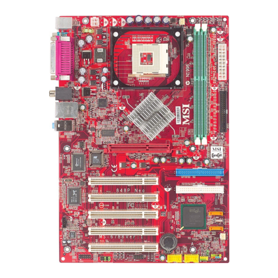
Page 11: Mainboard Layout
MS-6788 ATX Mainboard Mainboard Layout JPW1 Top : mouse Bottom: keyboard T:SP DIF Out B:USB ports T:LAN jack (Optional) B:USB ports T:Line-In Line-Out B:Mic BIOS Winb ond W83627THF Realtek 8110S/8100C Codec JAUD1 JSP1 848P Neo (MS-6788 v1.X) ATX Mainboard CP UFAN1 Intel 848P chipset... -
Page 12: Msi Special Features
MSI Special Features Color Management MSI has a unified color management rule for some connectors on the mainboards, which helps you to install the memory modules, expansion cards and other peripherals devices more easily and conveniently. Memory DDR DIMMs: light green... -
Page 13: Corecenter
MS-6788 ATX Mainboard CoreCenter (TM) CoreCenter - contains OC Menu panel, users can determine their processor and memory type to optimize its memory capacity. This all-in-one hardware console is advanced combination of the popular PC Alert and Fuzzy Logic. Including powerful function with hardware monitor, system alert and instinctive UI of overclocking, CoreCenter is just like your PC doctor that can detect, view and adjust the PC hardware and system status during real time operation. - Page 14 The exclusive OC Menu is fully de- veloped to support DDR400+ memory modules. By comprehensive validation of over 67 DDR400+ memory modules, MSI concluded best parameters for DRAM voltage, Vio and other BIOS settings. You can select DDR433, DDR450, DDR466 and DDR500 from DRAM frequency in BIOS setting.
-
Page 15: Live Monitor
Live Monitor™ The Live Monitor™ is a tool used to schedule the search for the latest BIOS/drivers version on the MSI Web site. To use the function, you need to install the “MSI Live Update 3” application. After installation, the “MSI Live Monitor” icon (as shown on the right) will appear on the screen. -
Page 16: Live Bios™/Live Driver
Live Update 3” icon (as shown on the right) will appear on the screen. Double click the “MSI Live Update 3” icon, and the following screen will appear: Five buttons are placed on the left column of the screen. Click the desired button to start the update process. -
Page 17: D-Bracket™ 2 (Optional)
MS-6788 ATX Mainboard D-Bracket™ 2 (Optional) D-Bracket™ 2 is a USB bracket integrating four Diagnostic LEDs, which use graphic signal display to help users understand their system. The LEDs provide up to 16 combinations of signals to debug the system. The 4 LEDs can detect all problems that fail the system, such as VGA, RAM or other failures. -
Page 18: Getting Started
Getting Started D-Bracket™ 2 Description Processor Initialization - This will show information regarding the processor (like brand name, system bus, etc…) Testing RTC (Real Time Clock) Initializing Video Interface - This will start detecting CPU clock, checking type of video onboard. -
Page 19: S-Bracket (Optional)
6-Channel Audio Function. SPDIF jack (optical) CPU Thermal Protection Aimed to prevent the CPU from overheating, MSI has developed a CPU Thermal Protection mechanism for Intel Protection mechanism works on a thermal signal sensor. If the mechanism senses an abnormal temperature rise, it will automatically shut down the system and the CPU temperature will then drop down and resume normal. -
Page 20: Round Cable (Optional)
Round Cable (Optional) Round cable is an enhanced cable for PCI IDE and Ultra DMA controller. It has the following benefits: Data transfer rate started by 133MB/s Backward compatibility (ATA33/66/100/133) Higher performance than traditional Flat cable (data rate) Improved data robustness Better airflow due to thinner ATA/133 cable Connect one end to the floppy disk drive... -
Page 21: Core Cell Chip
MS-6788 ATX Mainboard Core Cell Chip By diagnosing the current system utilization, the CoreCell™ Chip automatically tunes your motherboard to the optimal state, leading to less noise, longer duration, more power- saving and higher performance. Features of CoreCell™ PowerPro -- Saves up to 65% power. -
Page 22: Chapter 2. Hardware Setup
Chapter 2. Hardware Setup Hardware Setup This chapter tells you how to install the CPU, memory modules, and expansion cards, as well as how to setup the jumpers on the mainboard. Also, it provides the instructions on connecting the peripheral devices, such as the mouse, keyboard, etc. -
Page 23: Quick Components Guide
MS-6788 ATX Mainboard Quick Components Guide ATX1, p.2-9 Back Panel I/O, p.2-10 AGP Slot, p.2-26 PCI Slots, p.2-24 CD1, p.2-22 JSP1, p.2-18 JAUD1, p.2-20 CPUFAN1, p.2-15 CPU, p.2-3 JUSB2, p.2-22 JDB1, p.2-21 DDR DIMMs, p.2-7 ATX1, p.2-9 FDD1, p.2-15 IDE1, IDE2, p.2-16 SATA1, SATA2, p.2-16 SYSFAN1, p.2-15 JBAT1, p.2-23... -
Page 24: Central Processing Unit: Cpu
Memory Speed/CPU FSB Support Matrix Memory DDR 266 400 MHz 533 MHz 800 MHz MSI Reminds You... Overheating Overheating will seriously damage the CPU and system, always make sure the cooling fan can work properly to protect the CPU from overheating. Overclocking This motherboard is designed to support overclocking. -
Page 25: Cpu Installation Procedures For Socket 478
MS-6788 ATX Mainboard CPU Installation Procedures for Socket 478 Please turn off the power and unplug the power cord before installing the CPU. Pull the lever sideways away from the socket. Make sure to raise the lever up to a 90- degree angle. -
Page 26: Installing The Cpu Fan
CPU cooling fan and heatsink on top of the CPU. Follow the instructions below to install the Heatsink/Fan: Locate the CPU and its retention mechanism on the motherboard. retention mechanism Mount the fan on top of the heatsink. - Page 27 MS-6788 ATX Mainboard Connect the fan power cable from the mounted fan to the 3-pin fan power connector on the board. fan power cable NOTES...
-
Page 28: Memory
The mainboard provides 2 slots for 184-pin, 2.5V DDR DIMM modules and supports the memory size up to 2 GB without ECC,. You can install DDR266/ DDR333/DDR400 DDR SDRAM modules on the DDR DIMM slots. To operate properly, at least one DIMM module must be installed. Introduction to DDR SDRAM DDR (Double Data Rate) SDRAM is similar to conventional SDRAM, but doubles the rate by transferring data twice per cycle. -
Page 29: Ddr Dimm Module Combination
2. Insert the DIMM memory module vertically into the DIMM slot. Then push it in until the golden finger on the memory module is deeply inserted in the socket. MSI Reminds You... You can barely see the golden finger if the module is properly inserted in the socket. -
Page 30: Power Supply
The mainboard supports ATX power supply for the power system. Before inserting the power supply connector, always make sure that all components are installed properly to ensure that no damage will be caused. ATX 20-Pin Power Connector: ATX1 This connector allows you to connect to an ATX power supply. To connect to the ATX power supply, make sure the plug of the power supply is inserted in the proper orientation and the pins are aligned. -
Page 31: Back Panel
MS-6788 ATX Mainboard The back panel provides the following connectors: Parallel Mouse Keyboard COM A Mouse Connector The mainboard provides a standard PS/2 ® for attaching a PS/2 mouse. You can plug a PS/2 connector. The connector location and pin assignments are as follows: PS/2 Mouse (6-pin Female) 2-10 Back Panel... -
Page 32: Keyboard Connector
Keyboard Connector The mainboard provides a standard PS/2 ® tor for attaching a PS/2 keyboard. You can plug a PS/2 into this connector. PS/2 Keyboard (6-pin Female) USB Connectors The mainboard provides a UHCI (Universal Host Controller Interface) Universal Serial Bus root for attaching USB devices such as keyboard, mouse or other USB-compatible devices. -
Page 33: Serial Port Connector: Com A
MS-6788 ATX Mainboard Serial Port Connector: COM A The mainboard offers one 9-pin male DIN connector as serial port COM A. The ports are 16550A high speed communication ports that send/receive 16 bytes FIFOs. You can attach a serial mouse or other serial devices directly to the connectors. -
Page 34: Spdif-Out Port Connector
CD player, Tape player, or other audio devices. Mic is a connector for microphones. 1/8” Stereo Audio Connectors MSI Reminds You... For advanced audio application, ALC655 is provided to offer support for 6-channel audio operation and can turn rear audio connectors from 2-channel to 4-/6-channel audio. -
Page 35: Parallel Port Connector: Lpt1
MS-6788 ATX Mainboard Parallel Port Connector: LPT1 The mainboard provides a 25-pin female centronic connector as LPT. A parallel port is a standard printer port that supports Enhanced Parallel Port (EPP) and Extended Capabilities Parallel Port (ECP) mode. SIGNAL STROBE DATA0 DATA1 DATA2... -
Page 36: Connectors
GND. If the mainboard has a System Hardware Monitor chipset on-board, you must use a specially designed fan with speed sensor to take advantage of the CPU fan control. CPUFAN1 MSI Reminds You... Always consult the vendors for proper CPU cooling fan. Connectors FDD1... -
Page 37: Ata100 Hard Disk Connectors: Ide1 & Ide2
IDE2 (Secondary IDE Connector) IDE2 can also connect a Master and a Slave drive. MSI Reminds You... If you install two hard disks on cable, you must configure the second drive to Slave mode by setting its jumper. Refer to the hard disk documentation supplied by hard disk vendors for jumper setting instructions. -
Page 38: Serial Ata Hdd Connectors: Sata1, Sata2
1 hard disk drive. SATA2 SATA1 Optional Serial ATA cable MSI Reminds You... Please do not fold the Serial ATA cable into 90-degree angle. Otherwise, the loss of data may occur during transmission. Hardware Setup Pin Definition... -
Page 39: S-Bracket (Spdif) Connector: Jsp1 (Optional)
MS-6788 ATX Mainboard S-Bracket (SPDIF) Connector: JSP1 (Optional) The connector allows you to connect a S-Bracket for Sony & Philips Digital Interface (SPDIF). The S-Bracket offers 2 SPDIF jacks for digital audio transmission (one for optical fiber connection and the other for coaxial), and 2 analog Line-Out jacks for 4-channel audio output. -
Page 40: Front Panel Connectors: Jfp1 & Jfp2
Front Panel Connectors: JFP1 & JFP2 The mainboard provides two front panel connectors for electrical connection to the front panel switches and LEDs. JFP1 is compliant with Intel Front Panel I/O Connectivity Design Guide. Power Power Switch JFP1 Reset Switch SIGNAL HD_LED_P FP PWR/SLP... -
Page 41: Front Panel Audio Connector: Jaud1
AUD_RET_R HP_ON AUD_FPOUT_L AUD_RET_L MSI Reminds You... If you don’t want to connect to the front audio header, pins 5 & 6, 9 & 10 have to be jumpered in order to have signal output directed to the rear audio ports. Otherwise, the Line-Out connector on the back panel will not function. -
Page 42: D-Bracket™ 2 Connector: Jdb1 (Optional)
D-Bracket™ 2 Connector: JDB1 (Optional) The mainboard comes with a JDB1 connector for you to connect to D- Bracket™ 2. D-Bracket™ 2 is a USB Bracket that supports both USB1.1 & 2.0 spec. It integrates four LEDs and allows users to identify system problem through 16 various combinations of LED signals. -
Page 43: Cd-In Connector: Cd1
MS-6788 ATX Mainboard CD-In Connector: CD1 The connector is for CD-ROM audio connector. Front USB Connectors: JUSB2 & JUSB3 The mainboard provides two USB 2.0 pin headers JUSB2 & JUSB3 that ® are compliant with Intel I/O Connectivity Design Guide. USB 2.0 technology increases data transfer rate up to a maximum throughput of 480Mbps, which is 40 times faster than USB 1.1, and is ideal for connecting high-speed USB interface peripherals such as USB HDD, digital cameras, MP3 players,... -
Page 44: Jumpers
The motherboard provides the following jumpers for you to set the computer’s function. This section will explain how to change your motherboard’s function through the use of jumpers. Clear CMOS Jumper: JBAT1 There is a CMOS RAM on board that has a power supply from external battery to keep the data of system configuration. -
Page 45: Slots
MS-6788 ATX Mainboard The motherboard provides one AGP slot and five 32-bit PCI bus slots. AGP (Accelerated Graphics Port) Slot The AGP slot allows you to insert the AGP graphics card. AGP is an interface specification designed for the throughput demands of 3D graphics. -
Page 46: Chapter 3. Bios Setup
Chapter 3. BIOS Setup BIOS Setup This chapter provides information on the BIOS Setup program and allows you to configure the system for optimum use. You may need to run the Setup program when: An error message appears on the screen during the system booting up, and requests you to run SETUP. -
Page 47: Selecting The First Boot Device
MS-6788 ATX Mainboard Entering Setup Power on the computer and the system will start POST (Power On Self Test) process. When the message below appears on the screen, press <DEL> key to enter Setup. DEL:Setup F11:Boot Menu If the message disappears before you respond and you still wish to enter Setup, restart the system by turning it OFF and On or pressing the RESET button. -
Page 48: Control Keys
Control Keys < > Move to the previous item < > Move to the next item < > Move to the item in the left hand < > Move to the item in the right hand <Enter> Select the item <Esc>... -
Page 49: The Main Menu
MS-6788 ATX Mainboard The Main Menu Once you enter AMIBIOS NEW SETUP UTILITY, the Main Menu will appear on the screen. The Main Menu displays twelve configurable func- tions and two exit choices. Use arrow keys to move among the items and press <Enter>... - Page 50 BIOS Setup PC Health Status This entry shows your PC health status. Frequency/Voltage Control Use this menu to specify your settings for frequency/voltage control. Set Supervisor Password Use this menu to set Supervisor Password. Set User Password Use this menu to set User Password. Load High Performance Defaults Use this menu to load the BIOS values for the best system performance, but the system stability may be affected.
-
Page 51: Standard Cmos Features
MS-6788 ATX Mainboard Standard CMOS Features The items inside STANDARD CMOS SETUP menu are divided into 9 categories. Each category includes none, one or more setup items. Use the arrow keys to highlight the item you want to modify and use the <PgUp> or <PgDn>... - Page 52 Primary/Secondary/Third/Fourth IDE Master/Slave Press PgUp/<+> or PgDn/<-> to select the hard disk drive type. The specification of hard disk drive will show up on the right hand according to your selection. Type Cylinders Heads Write Precompensation Sectors Maximum Capacity LBA Mode Block Mode Fast Programmed I/O Modes...
-
Page 53: Advanced Bios Features
The items allow you to set the sequence of boot devices where BIOS attempts to load the disk operating system. MSI Reminds You... Available settings for “1st/2nd/3rd Boot Device” vary depend- ing on the bootable devices you have installed. For example, if you did not install a floppy drive, the setting “Floppy”... - Page 54 Try Other Boot Device Setting the option to Yes allows the system to try to boot from other devices if the system fails to boot from the 1st/2nd/3rd boot device. Full Screen LOGO Show This item enables you to show the company logo on the bootup screen. Settings are: Enabled Shows a still image (logo) on the full screen at boot.
- Page 55 Setting to Enabled will increase the system performance. Settings: Enabled, Disabled. Please disable this item if your operating system doesn’t support HT Function, or the unreliability and instability may occur. MSI Reminds You... Enabling the functionality of Hyper-Threading Technology for your computer system requires ALL of the following platform...
- Page 56 version supported by your operating system. To find out which version to use, consult the vendor of your operating system. Settings: 1.4, 1.1. APIC ACPI SCI IRQ This field is used to enable or disable the APIC (Advanced Programmable Interrupt Controller). Due to compliance to PC2001 design guide, the system is able to run in APIC mode.
-
Page 57: Advanced Chipset Features
MS-6788 ATX Mainboard Advanced Chipset Features MSI Reminds You... Change these settings only if you are familiar with the chipset. DRAM Timing Setting... Press <Enter> and to enter the sub-menu screen. Configure SDRAM Timing by SPD Selects whether DRAM timing is controlled by the SPD (Serial Presence Detect) EEPROM on the DRAM module. - Page 58 increases the system performance the most while 3 (clocks) provides the most stable performance. RAS# Precharge This item controls the number of cycles for Row Address Strobe (RAS) to be allowed to precharge. If insufficient time is allowed for the RAS to accumulate its charge before DRAM refresh, refresh may be incomplete and DRAM may fail to retain data.
-
Page 59: Power Management Features
MS-6788 ATX Mainboard Power Management Features MSI Reminds You... S3-related functions described in this section are available only when your BIOS supports S3 sleep mode. ACPI Standby State This item specifies the power saving modes for ACPI function. If your operating... - Page 60 Re-Call VGA BIOS at S3 Resuming Selecting Enabled allows BIOS to call VGA BIOS to initialize the VGA card when system wakes up (resumes) from S3 sleep state. The system resume time is shortened when you disable the function, but system will need an AGP driver to initialize the VGA card.
- Page 61 MS-6788 ATX Mainboard Set Monitor Events Press <Enter> and the following sub-menu appears. FDC/LPT/COM Ports, Primary/Secondary Master/Slave IDE These items specify if the BIOS will monitor the activity of the specified hardware peripherals or components. If set to Monitor, any activity detected on the specified hardware peripherals or components will wake up the system or prevent the system from entering the power saving modes.
- Page 62 Alarm Date Alarm Hour Alarm Minute Alarm Second MSI Reminds You... If you have changed this setting, you must let the system boot up until it enters the operating system, before this function will work. 01 ~ 31, Every Day...
-
Page 63: Pnp/Pci Configurations
MS-6788 ATX Mainboard PNP/PCI Configurations This section describes configuring the PCI bus system and PnP (Plug & Play) feature. PCI, or Peripheral Component Interconnect, is a system which allows I/O devices to operate at speeds nearing the speed the CPU itself uses when communicating with its special components. - Page 64 Init. Graphics Adapter Priority This setting specifies which VGA card is your primary graphics adapter. Setting options are: AGP/PCI The system initializes the installed AGP card first. If an AGP card is not available, it will initialize the PCI VGA card.
- Page 65 MS-6788 ATX Mainboard Onboard I/O is configured by AMIBIOS. All IRQs used by onboard I/O are configured as PCI/PnP. If all IRQs are set to ISA/EISA, and IRQ 14/15 are allocated to the onboard PCI IDE, IRQ 9 will still be available for PCI and PnP devices.
-
Page 66: Integrated Peripherals
BIOS Setup Integrated Peripherals Please note that the options showed on your BIOS might be different depending on the motherboard you buy. USB Controller This setting is used to enable/disable the onboard USB controllers. USB Device Legacy Support Set to Enabled if your need to use any USB 1.1/2.0 device in the operating system that does not support or have any USB 1.1/2.0 driver installed, such as... - Page 67 14 and 15 IRQs, while Native Mode means you may use all the available IRQs. Setting options: Legacy Mode, Native Mode. MSI Reminds You... There are two modes to select: Legacy mode and Native mode. Legacy Mode: * In this mode, system BIOS just assign the traditional 14 and 15 IRQs to use for HDD.
- Page 68 S-ATA Keep Enabled This item is available for you to enable/disable the onboard S-ATA. Setting options: Yes, No. P-ATA Keep Enabled This item is available for you to enable/disable the onboard P-ATA. Set- ting options: Yes, No. P-ATA Channel Selection This item is available for you to select the parallel ATA channel.
- Page 69 MS-6788 ATX Mainboard OnBoard FDC Select Enabled if your system has a floppy disk controller (FDD) installed on the system board and you wish to use it. Option Description Auto BIOS will automatically determine whether to enable the onboard Floppy controller or not. Enabled Enables the onboard Floppy controller.
-
Page 70: Pc Health Status
BIOS Setup PC Health Status This section shows the status of your CPU, fan, overall system status, etc. Monitor function is available only if there is hardware monitoring mechanism onboard. CPU/System Temperature, CPU/System Fan Speed, Vcore, 3.3V, +5.0V, Battery, +5V SB These items display the current status of all of the monitored hardware devices/ components such as CPU voltages, temperatures and all fans’... -
Page 71: Frequency/Voltage Control
’s newly developed CoreCell to detect the load balance of CPU while running programs, and to adjust the best CPU frequency automatically. When the motherboard detects CPU is running programs, it will speed up CPU automatically to make the program run smoothly and faster. - Page 72 Defaults (Normal), too CPU Ratio Selection This setting controls the multiplier that is used to determine the internal clock speed of the processor relative to the external or motherboard clock speed. ’s exclusive technology, specializing in opti- BIOS Setup...
- Page 73 PSB 533: 133-500MHz PSB 800: 200-500MHz Spread Spectrum When the motherboard’s clock generator pulses, the extreme values (spikes) of the pulses creates EMI (Electromagnetic Interference). The Spread Spectrum function reduces the EMI generated by modulating the pulses so that the spikes of the pulses are reduced to flatter curves.
- Page 74 CPU Vcore The setting is adjustable if you set the “CPU Vcore Adjust” to “Yes”. MSI Reminds You... Changing CPU Ratio/Vcore could result in the instability of the system; therefore, it is NOT recommended to change the default setting for long-term usage.
-
Page 75: Set Supervisor/User Password
Always, the password is required both at boot and at entry to Setup. If set to Setup, password prompt only occurs when you try to enter Setup. MSI Reminds You... About Supervisor Password & User Password: Supervisor password:... -
Page 76: Load High Performance/Bios Setup Defaults
Pressing ‘Enter’ loads the default BIOS values that enable the best sys- tem performance but may lead to a stability issue. MSI Reminds You... The option is for power or overclocking users only. Use of high performance defaults will tighten most timings to increase the system performance. -
Page 77: Appendix: Using 4- Or 6-Channel Audio Function
Using 2-, 4- or 6-Channel Audio Function Appendix: Using 2-, 4- & 6-Channel Audio Function The mainboard is equipped with Realtek ALC655 chip, which provides support for 6-channel audio output, including 2 Front, 2 Rear, 1 Center and 1 Subwoofer channel. ALC655 allows the board to attach 4 or 6 speakers for better surround sound effect. -
Page 78: Installing The Audio Driver
1. Insert the companion CD into the CD-ROM drive. The setup screen will automatically appear. 2. Click Realtek AC97 Audio Drivers. MSI Reminds You... The AC97 Audio Configuration continuous update to enhance audio applications. Hence, the program screens shown here in this appendix may be slightly different from the latest software utility and shall be held for reference only. - Page 79 3. Click Next to install the AC’97 Audio software. 4. Click Finish to restart the system. Using 2-, 4- or 6-Channel Audio Function Click here Click here Select this option...
-
Page 80: Software Configuration
MS-6788 ATX Mainboard Software Configuration After installing the audio driver, you are able to use the 4-/6-channel audio feature now. Click the audio icon right corner of the screen to activate the AC97 Audio Configuration. Sound Effect Here you can select a sound effect you like from the Environment list. You may also edit the properties for an environment as you wish by clicking the Edit button, then just scroll the bar in the bottom for each property to adjust. - Page 81 Here it provides the Karaoke function which will automatically remove human voice (lyrics) and leave melody for you to sing the song. Note that this function applies only for 2-channel audio operation. Just check the Voice Cancellation box and then click OK to activate the Karaoke function.
-
Page 82: Equalizer
MS-6788 ATX Mainboard Equalizer Here you regulate each equalizer for current playing digital sound sources. You may choose the provided sound effects, and the equalizer will adjust automatically. If you like, you may also load an equalizer setting or make an new equalizer setting to save as an new one by using the buttons Load and Save. -
Page 83: Speaker Configuration
Speaker Configuration In this tab, you can easily configure your multi-channel audio function and speakers. 1. Select the audio configuration below which is identical to the audio jack in your mainboard. For 848P Neo, you will have to choose 6CH+ S/PDIF (Coaxial). -
Page 84: Speaker Test
MS-6788 ATX Mainboard Speaker Test You can use this tab to test each connected speaker to ensure if 4- or 6- channel audio operation works properly. If any speaker fails to make sound, then check whether the cable is inserted firmly to the connector or replace the bad speakers with good ones. -
Page 85: Hrtf Demo
MSI Reminds You... 1. 6 speakers appear on the “Speaker Test” tab only when you select “6-Channel Mode” in the “Number of Speakers” col- umn in “Speaker Configuration” tab. If you select “4-Chan- nel Mode”, only 4 speakers appear on the window. -
Page 86: General
MS-6788 ATX Mainboard General In this tab it provides some information about the AC97 Audio Configu- ration utility, including Audio Driver Version, DirectX Version, Audio Control- ler & AC97 Codec. You may also select the language of this utility by choosing from the Language list. -
Page 87: Using 2-, 4- & 6- Channel Audio Function
Using 2-, 4- & 6- Channel Audio Function Connecting the Speakers without the Optional S-Bracket When you have set the Multi-Channel Audio Function mode properly in the software utility, connect your speakers to the correct phone jacks in accordance with the setting in software utility. 2-Channel Mode for Stereo-Speaker Output Refer to the following diagram and caption for the function of each phone jack on the back panel when 2-Channel Mode is selected. - Page 88 MS-6788 ATX Mainboard 4-Channel Mode for 4-Speaker Output The audio jacks on the back panel always provide 2-channel analog audio output function, however these audio jacks can be transformed to 4- or 6- channel analog audio jacks by selecting the corresponding multi-channel operation from No.
- Page 89 Out function when 6-Channel Mode for 6-Speaker Output is selected. MSI Reminds You... If the audio signals coming from the Center and Subwoofer speaker are swapped when you play video or music on the computer, a converter may be required to exchange center and subwoofer audio signals.
- Page 90 Coaxial SPDIF jack SPDIF Coaxial jack S-Bracket MSI Reminds You... When any Multi-Channel Audio Mode is selected, you may also connect your speakers to the Optical or Coaxial SPDIF phone jack on the S-Bracket to exprience digital surround sound effect.
- Page 91 4-Channel Analog Audio Output Line In Line Out (Front channels) Optical SPDIF jack Coaxial SPDIF jack Line Out (Center and Subwoofer channel, but no functioning in this mode) Line Out (Rear channels) SPDIF Coaxial jack Using 2-, 4- or 6-Channel Audio Function Description: Connect two speakers to back panel’s Line Out connector...
- Page 92 MS-6788 ATX Mainboard 6-Channel Analog Audio Output Line In Line Out (Front channels) Optical SPDIF jack Coaxial SPDIF jack Line Out (Center and Subwoofer channel) Line Out (Rear channels) SPDIF Coaxial jack A-16 Description: Connect two speakers to back panel’s Line Out connector and four speakers to both Line Out connectors of S-Bracket.
Need help?
Do you have a question about the 848P Neo-S and is the answer not in the manual?
Questions and answers