Table of Contents
Advertisement
Advertisement
Table of Contents

Related Manuals for MSI 875P Neo-FIS2R


Summary of Contents for MSI 875P Neo-FIS2R
- Page 1 875P Neo P Series MS-6758 (v2.X) ATX Mainboard Version 2.0 G52-M6758X8...
-
Page 2: Fcc-B Radio Frequency Interference Statement
Manual Rev: 2.0 Release Date: January 2004 FCC-B Radio Frequency Interference Statement This equipment has been tested and found to comply with the limits for a class B digital device, pursuant to part 15 of the FCC rules. These limits are designed to provide reasonable protection against harmful interference when the equip- ment is operated in a commercial environment. -
Page 3: Copyright Notice
Copyright Notice The material in this document is the intellectual property of MICRO-STAR INTERNATIONAL. We take every care in the preparation of this document, but no guarantee is given as to the correctness of its contents. Our products are under continual improvement and we reserve the right to make changes without notice. -
Page 4: Safety Instructions
Safety Instructions Always read the safety instructions carefully. Keep this User’s Manual for future reference. Keep this equipment away from humidity. Lay this equipment on a reliable flat surface before setting it up. The openings on the enclosure are for air convection hence protects the equipment from overheating. -
Page 5: Table Of Contents
Revision History ................... iii Safety Instructions ..................iv Chapter 1. Getting Started ................ 1-1 Mainboard Specifications ..............1-2 Mainboard Layout ................1-4 MSI Special Features ................1-5 Color Management ................ 1-5 CoreCenter ..................1-6 Live BIOS™/Live Driver™ ............1-8 Live Monitor™ ................1-9 D-Bracket™... - Page 6 Back Panel ..................2-10 Mouse Connector ............... 2-10 Keyboard Connector ..............2-11 USB Connectors ................2-11 1394 Ports ..................2-12 RJ-45 LAN Jack: Giga-bit LAN (Intel 82547EI) ......2-12 Serial Port Connector: COM A ............ 2-13 Audio Port Connectors ............... 2-13 Parallel Port Connector: LPT1 ............
- Page 7 Selecting the First Boot Device ............. 3-2 Control Keys ................. 3-3 Getting Help .................. 3-3 The Main Menu ................... 3-4 Standard CMOS Features ..............3-6 Advanced BIOS Features ..............3-8 Advanced Chipset Features ............... 3-12 Power Management Features ............. 3-15 PNP/PCI Configurations ..............
-
Page 8: Chapter 1. Getting Started
Getting Started Chapter 1. Getting Started Getting Started Thank you for choosing the 875P Neo P series (MS-6758) ® v2.X ATX mainboard. The 875P Neo P series is based on Intel 875P & ICH5R chipsets for optimal system efficiency. Designed ®... -
Page 9: Mainboard Specifications
MS-6758 ATX Mainboard Mainboard Specifications ® Supports Intel P4 Northwood/Prescott (Socket 478) processors. FSB 533~800MHz, depending on the North Bridge integrated. Supports up to 3.4GHz or higher speed. Chipset ® Intel Canterwood (875P) chipset - Supports FSB 800/533MHz. - Supports AGP 8X interface. - Supports ECC memory. - Page 10 Getting Started On-Board Peripherals On-Board Peripherals include: - 1 floppy port supports 2 FDDs with 360K, 720K, 1.2M, 1.44M and 2.88Mbytes - 1 serial port COMA - 1 parallel port supports SPP/EPP/ECP mode - 8 USB 2.0 ports (Rear * 4/ Front * 4) - 1 Line-In/Line-Out/Mic-In/Real Speaker Out/Center-Subwoofer Speaker Out/S/PDIF Out audio port - 1 RJ45 LAN jack (Optional)
-
Page 11: Mainboard Layout
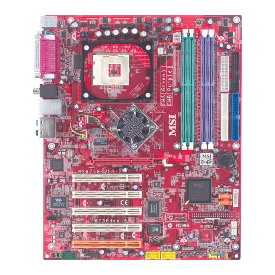
MS-6758 ATX Mainboard Mainboard Layout Top : mouse Bottom: keyboard JPWR2 CFAN1 Top : Parallel Port Bottom: COMA 1394 Port Mini 1394 Port T: SPDIF Out B: USB ports T: LAN jack B: USB ports Line-In Line-Out Intel B:Mic Canterwood NBFAN1 Line-Out (875P) -
Page 12: Msi Special Features
Getting Started MSI Special Features Color Management MSI has an unified color management rule for some connectors on the mainboards, which helps you to install the memory modules, expansion cards and other peripherals devices more easily and conveniently. Dual Memory DDR DIMMs: Channel A is light green, Channel B is... -
Page 13: Corecenter
MS-6758 ATX Mainboard CoreCenter (TM) CoreCenter - contains OC Menu panel, users can determine their processor and memory type to optimize its memory capacity. This all-in-one hardware console is advanced combination of the popular PC Alert and Fuzzy Logic. Including powerful function with hardware monitor, system alert and instinctive UI of overclocking, CoreCenter is just like your PC doctor that can detect, view and adjust the PC hardware and system status during real time operation. - Page 14 Getting Started Left-wing: Current system status In the left sub-menu, you can configure the settings of FSB, Vcore, Memory Voltage and AGP Voltage by clicking the radio button in front of each item and make it available (the radio button will be lighted as yellow when selected), use the “+”...
-
Page 15: Live Bios™/Live Driver
Live Update 3” icon (as shown on the right) will appear on the screen. Double click the “MSI Live Update 3” icon, and the following screen will appear: Five buttons are placed on the left column of the screen. Click the desired button to start the update process. -
Page 16: Live Monitor
Live Monitor™ The Live Monitor™ is a tool used to schedule the search for the latest BIOS/drivers version on the MSI Web site. To use the function, you need to install the “MSI Live Update 3” application. After installation, the “MSI Live Monitor” icon (as shown on the right) will appear on the screen. -
Page 17: D-Bracket™ 2 (Optional)
MS-6758 ATX Mainboard D-Bracket™ 2 (Optional) D-Bracket™ 2 is a USB bracket integrating four Diagnostic LEDs, which use graphic signal display to help users understand their system. The LEDs provide up to 16 combinations of signals to debug the system. The 4 LEDs can detect all problems that fail the system, such as VGA, RAM or other failures. - Page 18 Getting Started D-Bracket™ 2 Description Processor Initialization - This will show information regarding the processor (like brand name, system bus, etc…) Testing RTC (Real Time Clock) Initializing Video Interface - This will start detecting CPU clock, checking type of video onboard.
-
Page 19: Round Cable (Optional)
Connect to the slave drive. CPU Thermal Protection Aimed to prevent the CPU from overheating, MSI has developed a CPU ® Thermal Protection mechanism for Intel CPU platform. This CPU Thermal Protection mechanism works on a thermal signal sensor. If the mechanism senses an abnormal temperature rise, it will automatically shut down the system and the CPU temperature will then drop down and resume normal. -
Page 20: Chapter 2. Hardware Setup
Hardware Setup Chapter 2. Hardware Setup Hardware Setup This chapter tells you how to install the CPU, memory modules, and expansion cards, as well as how to setup the jumpers on the mainboard. Also, it provides the instructions on connecting the peripheral devices, such as the mouse, keyboard, etc. -
Page 21: Quick Components Guide
MS-6758 ATX Mainboard Quick Components Guide CFAN1, p.2-15 JPWR2, p.2-9 CPU, p.2-3 DDR DIMMs, p.2-7 JPWR1, p.2-9 FDD1, p.2-15 Back Panel I/O, p.2-10 IDE1, IDE2, NBFAN1, p.2-15 p.2-16 BATT AGP Slot, p.2-23 JBAT1, p.2-22 PCI Slots, p.2-23 SER1, SER2, p.2-17 JCD1, p.2-20 PFAN1, p.2-15 BIOS... -
Page 22: Central Processing Unit: Cpu
FSB533 FSB800 OK * OK * OK * *: Overclocking spec. MSI Reminds You... Overheating Overheating will seriously damage the CPU and system, always make sure the cooling fan can work properly to protect the CPU from overheating. Overclocking This motherboard is designed to support overclocking. However, please make sure your components are able to tolerate such abnormal setting, while doing overclocking. -
Page 23: Cpu Installation Procedures For Socket 478
MS-6758 ATX Mainboard CPU Installation Procedures for Socket 478 Please turn off the power and unplug the power cord before Open Lever installing the CPU. Pull the lever sideways away Sliding 90 degree Plate from the socket. Make sure to raise the lever up to a 90- degree angle. -
Page 24: Installing The Cpu Fan
Hardware Setup Installing the CPU Fan As processor technology pushes to faster speeds and higher performance, thermal management becomes increasingly important. To dissipate heat, you need to attach the CPU cooling fan and heatsink on top of the CPU. Follow the instructions below to install the Heatsink/Fan: Locate the CPU and its retention Position the heatsink onto the reten-... - Page 25 MS-6758 ATX Mainboard C o n n e ct th e f a n p o w e r ca b l e f r om th e m o u n t ed f a n to th e 3- p i n f a n p o w e r con n e ctor on th e b o a r d .
-
Page 26: Memory
Hardware Setup Memory The mainboard provides 4 slots for 184-pin, 2.5V DDR DIMM with 8 memory banks. You can install DDR333 / DDR400 / DDR433 / DDR466 / DDR500 / DDR533 SDRAM modules on the DDR DIMM slots (DIMM 1~4). To operate properly, at least one DIMM module must be installed. -
Page 27: Installing Ddr Modules
128MB~1GB 128MB~1GB 128MB~1GB 128MB~1GB 512MB~4GB MSI Reminds You... Dual-channel DDR works ONLY in the 3 combinations listed in the table above. Installing DDR Modules 1. The DDR DIMM has only one notch on the center of module. The module will only fit in the right orientation. -
Page 28: Power Supply
5V_SB JPWR1 ATX 12V Power Connector: JPWR2 This 12V power connector is used to provide power to the CPU. JPWR2 Pin Definition SIGNAL JPWR2 MSI Reminds You... Power supply of 300 (and up) watt is highly recommended for system stability. -
Page 29: Back Panel
MS-6758 ATX Mainboard Back Panel The back panel provides the following connectors: L-in RS-Out SPDIF Out Parallel (Optional) Mouse Keyboard COMA 1394 Port USB Ports USB Ports FS-Out CS-Out SPDIF Out Mini 1394 Port Mouse Connector The mainboard provides a standard PS/2 ®... -
Page 30: Keyboard Connector
Hardware Setup Keyboard Connector ® The mainboard provides a standard PS/2 keyboard mini DIN connector ® ® for attaching a PS/2 keyboard. You can plug a PS/2 keyboard directly into this connector. Pin Definition SIGNAL DESCRIPTION Keyboard DATA Keyboard DATA No connection Ground Keyboard Clock... -
Page 31: 1394 Ports
MS-6758 ATX Mainboard 1394 Ports There are two 1394 ports on the back panel providing the connection for 1394 devices. Mini 1394 port 1394 port RJ-45 LAN Jack: Giga-bit LAN (Intel 82547EI) The mainboard provides standard RJ-45 jack for connection to Local Area Network (LAN). -
Page 32: Serial Port Connector: Com A
Hardware Setup Serial Port Connector: COM A The mainboard offers one 9-pin male DIN connector as serial port COM A. The port is a 16550A high speed communication port that sends/receives16 bytes FIFOs. You can attach a serial mouse or other serial devices directly to the connectors. -
Page 33: Parallel Port Connector: Lpt1
MS-6758 ATX Mainboard Parallel Port Connector: LPT1 The mainboard provides a 25-pin female centronic connector as LPT. A parallel port is a standard printer port that supports Enhanced Parallel Port (EPP) and Extended Capabilities Parallel Port (ECP) mode. Pin Definition SIGNAL DESCRIPTION STROBE... -
Page 34: Connectors
CFAN1 SFAN1 PFAN1 NBFAN1 MSI Reminds You... 1. Always consult the vendors for proper CPU cooling fan. 2. CFAN1 supports the fan control. You can install Core Center utility that will automatically control the CPU fan speed ac- cording to the actual CPU temperature. -
Page 35: Ata100 Hard Disk Connectors: Ide1 & Ide2
IDE2 (Secondary IDE Connector) IDE2 can also connect a Master and a Slave drive. MSI Reminds You... If you install two hard disks on cable, you must configure the second drive to Slave mode by setting its jumper. Refer to the hard disk documentation supplied by hard disk vendors for jumper setting instructions. -
Page 36: Serial Ata/Serial Ata Raid Connectors Controlled By Ich5R: Ser1, Ser2 (Optional)
Take out the dust cover and connect to the hard disk devices Connect to serial ATA ports MSI Reminds You... Please do not fold the serial ATA cable in a 90-degree angle, which will cause the loss of data during the transmission. 2-17... -
Page 37: Chassis Intrusion Switch Connector: J8
MS-6758 ATX Mainboard Chassis Intrusion Switch Connector: J8 This connector is connected to a 2-pin chassis switch. If the chassis is opened, the switch will be short. The system will record this status and show a warning message on the screen. To clear the warning, you must enter the BIOS utility and clear the record. -
Page 38: Ieee 1394 Connector: J1394_1 (Optional)
Hardware Setup IEEE 1394 Connector: J1394_1 (Optional) The mainboard provides one IEEE1394 pin header that allows you to connect IEEE 1394 ports via an external IEEE1394 bracket (optional). J1394_1 J1394 Pin Definition SIGNAL SIGNAL TPA+ TPA- Ground Ground TPB+ TPB- Cable power Cable power Key (no pin) -
Page 39: Cd-In Connector: Jcd1
MS-6758 ATX Mainboard CD-In Connector: JCD1 The connector is for CD-ROM audio connector. JCD1 D-Bracket™ 2 Connector: JLED1 The mainboard comes with a JLED1 connector for you to connect to D- Bracket™ 2. D-Bracket™ 2 is a USB Bracket that supports both USB1.1 & 2.0 spec. -
Page 40: Front Usb Connectors: Jusb2 & Jusb3
Left channel audio signal to front panel AUD_RET_L Left channel audio signal return from front panel MSI Reminds You... If you don’t want to connect to the front audio header, pins 5 & 6, 9 & 10 have to be jumpered in order to have signal output directed to the rear audio ports. -
Page 41: Jumpers
JBAT1 Keep Data Clear Data MSI Reminds You... You can clear CMOS by shorting 2-3 pin while the system is off. Then return to 1-2 pin position. Avoid clearing the CMOS while the system is on; it will damage the mainboard. -
Page 42: Slots
Hardware Setup Slots The motherboard provides one AGP slot and five 32-bit PCI bus slots. AGP (Accelerated Graphics Port) Slot The AGP slot allows you to insert the AGP graphics card. AGP is an interface specification designed for the throughput demands of 3D graphics. It introduces a 66MHz, 32-bit channel for the graphics controller to directly access main memory. -
Page 43: Chapter 3. Bios Setup
BIOS Setup Chapter 3. BIOS Setup BIOS Setup This chapter provides information on the BIOS Setup program and allows you to configure the system for optimum use. You may need to run the Setup program when: An error message appears on the screen during the system booting up, and requests you to run SETUP. -
Page 44: Entering Setup
MS-6758 ATX Mainboard Entering Setup Power on the computer and the system will start POST (Power On Self Test) process. When the message below appears on the screen, press <DEL> key to enter Setup. DEL: Setup F11: Boot Menu F12: Network boot TAB: Logo If the message disappears before you respond and you still wish to enter Setup, restart the system by turning it OFF and On or pressing the RESET... -
Page 45: Control Keys
BIOS Setup Control Keys < Move to the previous item < Move to the next item < Move to the item in the left hand < Move to the item in the right hand <Enter> Select the item <Esc> Jumps to the Exit menu or returns to the main menu from a submenu <+/PU>... -
Page 46: The Main Menu
MS-6758 ATX Mainboard The Main Menu Once you enter AMIBIOS NEW SETUP UTILITY, the Main Menu will appear on the screen. The Main Menu displays twelve configurable func- tions and two exit choices. Use arrow keys to move among the items and press <Enter>... - Page 47 BIOS Setup Integrated Peripherals Use this menu to specify your settings for integrated peripherals. PC Health Status This entry shows your PC health status. Frequency/Voltage Control Use this menu to specify your settings for frequency/voltage control. Set Supervisor Password Use this menu to set Supervisor Password. Set User Password Use this menu to set User Password.
-
Page 48: Standard Cmos Features
MS-6758 ATX Mainboard Standard CMOS Features The items inside STANDARD CMOS SETUP menu are divided into 9 categories. Each category includes none, one or more setup items. Use the arrow keys to highlight the item you want to modify and use the <PgUp> or <PgDn>... - Page 49 BIOS Setup Primary/Secondary/Third/Fourth IDE Master/Slave Press PgUp/<+> or PgDn/<-> to select the hard disk drive type. The specifica- tion of hard disk drive will show up on the right hand according to your selection. Type Select how to define the HDD parameters Cylinders Enter cylinder number Heads...
-
Page 50: Advanced Bios Features
The items allow you to set the sequence of boot devices where BIOS attempts to load the disk operating system. MSI Reminds You... Available settings for “1st/2nd/3rd Boot Device” vary depend- ing on the bootable devices you have installed. For example, if you did not install a floppy drive, the setting “Floppy”... - Page 51 BIOS Setup Try Other Boot Device Setting the option to Yes allows the system to try to boot from other devices if the system fails to boot from the 1st/2nd/3rd boot device. Full Screen LOGO Show This item enables you to show the company logo on the bootup screen. Settings are: Enabled Shows a still image (logo) on the full screen at boot.
- Page 52 This field is used to enable or disable the Hyper Threading function. Setting to Enabled will increase the system performance. Settings: Enabled, Disabled. MSI Reminds You... Enabling the functionality of Hyper-Threading Technology for your computer system requires ALL of the following platform Components: ®...
- Page 53 BIOS Setup MPS Revision This field allows you to select which MPS (Multi-Processor Specification) version to be used for the operating system. You need to select the MPS version supported by your operating system. Settings: 1.4 and 1.1. APIC ACPI SCI IRQ This field is used to enable or disable the APIC (Advanced Programmable Inter- rupt Controller).
-
Page 54: Advanced Chipset Features
MS-6758 ATX Mainboard Advanced Chipset Features MSI Reminds You... Change these settings only if you are familiar with the chipset. DRAM Timing Setting... Press <Enter> and to enter the sub-menu screen. Configure DRAM Timing by SPD Selects whether DRAM timing is controlled by the SPD (Serial Presence Detect) EEPROM on the DRAM module. - Page 55 BIOS Setup DRAM CAS# Latency This controls the timing delay (in clock cycles) before SDRAM starts a read command after receiving it. Settings: 2, 2.5 (clocks). 2 (clocks) increases the system performance the most while 2.5 (clocks) provides the most stable performance. DRAM RAS# Precharge This item controls the number of cycles for Row Address Strobe (RAS) to be allowed to precharge.
- Page 56 MS-6758 ATX Mainboard Memory Hole In order to improve performance, certain space in memory can be reserved for ISA peripherals. This memory must be mapped into the memory space below 16MB. When this area is reserved, it cannot be cached. Settings: Disabled, 15MB-16MB.
-
Page 57: Power Management Features
BIOS Setup Power Management Features MSI Reminds You... S3-related functions described in this section are available only when your BIOS supports S3 sleep mode. APCI Standby State This item specifies the power saving modes for ACPI function. If your operat-... - Page 58 MS-6758 ATX Mainboard Re-Call VGA BIOS at S3 Resuming Selecting Enabled allows BIOS to call VGA BIOS to initialize the VGA card when system wakes up (resumes) from S3 sleep state. The system resume time is shortened when you disable the function, but system will need an AGP driver to initialize the VGA card.
- Page 59 BIOS Setup FDC/LPT/COM Ports, Primary/Secondary Master/Slave IDE These items specify if the BIOS will monitor the activity of the specified hardware peripherals or components. If set to Monitor, any activity detected on the specified hardware peripherals or components will wake up the system or prevent the system from entering the power saving modes.
- Page 60 Alarm Minute 00 ~ 59 Alarm Second 00 ~ 59 MSI Reminds You... If you have changed this setting, you must let the system boot up until it enters the operating system, before this function will work. Keyboard PowerOn Function This controls how the PS/2 keyboard can power on the system.
-
Page 61: Pnp/Pci Configurations
BIOS Setup PNP/PCI Configurations This section describes configuring the PCI bus system and PnP (Plug & Play) feature. PCI, or Peripheral Component Interconnect, is a system which allows I/O devices to operate at speeds nearing the speed the CPU itself uses when communicating with its special components. - Page 62 MS-6758 ATX Mainboard Primary Graphics Adapter This setting specifies which VGA card is your primary graphics adapter. Set- ting options are: The system initializes the installed AGP card first. If the AGP card is not available, it will initialize the PCI VGA card. The system initialize the installed PCI VGA card first.
- Page 63 BIOS Setup are allocated to the onboard PCI IDE, IRQ 9 will still be available for PCI and PnP devices. Available settings: ISA/EISA and PCI/PnP. Set DMAs to PnP or ISA Press <Enter> to enter the sub-menu and the following screen appears: DMA Channel 0/1/3/5/6/7 These items specify the bus that the system DMA (Direct Memory Access) channel is using.
-
Page 64: Integrated Peripherals
MS-6758 ATX Mainboard Integrated Peripherals Please note that the options showed on your BIOS might be different depending on the motherboard you buy. USB Controller This setting is used to enable/disable the onboard USB controllers. USB Device Legacy Support Set to All Device if your need to use any USB 1.1/2.0 device in the operating system that does not support or have any USB 1.1/2.0 driver installed, such as DOS and SCO Unix. - Page 65 S-ATA Ports Definition This allows you to set the definition of serial ATA ports. MSI Reminds You... If you wish to use S-ATA devices on your mainboard while the ATA devices connected to the IDE1 and IDE2 are also available,...
- Page 66 MS-6758 ATX Mainboard Configure S-ATA as RAID This item is available for you to configure S-ATA as onboard RAID. Setting: Yes, No. On-Chip IDE Settings in Windows XP/2000 Settings in Windows 98/ME Configuration (Maximum of 6 devices) (Maximum of 4 devices) Legacy Mode (not available) On-Chip ATA(s)
- Page 67 BIOS Setup Set Super I/O Press <Enter> to enter the sub-menu and the following screen appears: OnBoard FDC Select Enabled if your system has a floppy disk controller (FDD) installed on the system board and you wish to use it. Option Description Auto...
- Page 68 MS-6758 ATX Mainboard Parallel Port IRQ When Onboard Parallel Port is set to Auto, the item shows Auto indicating that BIOS determines the IRQ for the parallel port automatically. Parallel Port DMA Channel This feature needs to be configured only when Parallel Port Mode is set to the ECP mode.
-
Page 69: Pc Health Status
BIOS Setup PC Health Status This section shows the status of your CPU, fan, overall system status, etc. Monitor function is available only if there is hardware monitoring mechanism onboard. Chassis Intrusion The field enables or disables the feature of recording the chassis intrusion status and issuing a warning message if the chassis is once opened. -
Page 70: Frequency/Voltage Control
Use this menu to specify your settings for frequency/voltage control. Performance Mode This item allows you to control the MAT (memory acceleration technology) function of CPU. MAT is MSI ’s exclusive technology, specializing in opti- mizing the data transfer rate among CPU, north bridge chip and memory, and also in procuring better memory performance and bandwidth up to 10%. - Page 71 Defaults (Normal), too D.O.T. Range (D.O.T) Dynamic Overclocking Technology is the automatic overclocking function, included in the MSI ’s newly developed CoreCell Technology. It is designed to detect the load balance of CPU while running programs, and to adjust the best CPU frequency automatically.
- Page 72 PSB 533: 266, 333, Auto, 400, 433, 450, 466, 500, 354 (3:4). PSB 800: 266, 333, 400, Auto, 433, 450, 466, 500, 532, 501 (4:5), 533 (3:4). MSI Reminds You... The value plus a ratio (CPU: DDR) with parentheses means the non-synchronous overclocking.
- Page 73 CPU Voltage (V) (for Northwood CPU only) The setting is adjustable if you set the “CPU Vcore Adjust” to “Yes”. MSI Reminds You... Changing CPU Ratio/Vcore could result in the instability of the system; therefore, it is NOT recommended to change the default setting for long-term usage.
-
Page 74: Set Supervisor/User Password
FEATURES menu. If the PASSWORD CHECK option is set to Always, the password is required both at boot and at entry to Setup. If set to Setup, password prompt only occurs when you try to enter Setup. MSI Reminds You... About Supervisor Password & User Password: Supervisor password: Can enter and change the settings of the setup menu. -
Page 75: Load High Performance/Bios Setup Defaults
Pressing ‘Enter’ loads the default BIOS values that enable the best system performance but may lead to a stability issue. MSI Reminds You... The option is for power or overclocking users only. Use of high performance defaults will tighten most timings to increase the system performance. -
Page 76: Appendix A: Using 2-, 4-, 6- Or 8- Channel Audio Function
Using 2-, 4-, 6- or 8- Channel Audio Function Appendix A: Using 2-, 4-, 6- or 8- Channel Audio Function The mainboard is equipped with Realtek ALC850 chip, which provides support for 8-channel audio output, including 2 Front, 2 Rear, 1 Center and 1 Subwoofer channel. -
Page 77: Installing The Audio Driver
1. Insert the companion CD into the CD-ROM drive. The setup screen will automatically appear. 2. Click Realtek AC97 Audio Drivers. Click here MSI Reminds You... The AC97 Audio Configuration software utility is under continuous update to enhance audio applications. Hence, the... - Page 78 Using 2-, 4-, 6- or 8- Channel Audio Function 3. Click Next to install the AC’97 Audio software. Click here 4. Click Finish to restart the system. Select this option Click here...
-
Page 79: Software Configuration
MS-6758 ATX Mainboard Software Configuration After installing the audio driver, you are able to use the 2-, 4-, 6- or 8- channel audio feature now. Click the audio icon from the system tray at the lower-right corner of the screen to activate the AC97 Audio Configuration. It is also available to enable the audio driver by clicking the Sound Effect Manager from the Control Panel. -
Page 80: Sound Effect
Using 2-, 4-, 6- or 8- Channel Audio Function Sound Effect Here you can select a sound effect you like from the Environment list. Edit You may also edit the properties for an environment as you wish by clicking the “Edit” button, then just scroll the bar in the bottom for each property to adjust. - Page 81 MS-6758 ATX Mainboard You may choose the provided sound effects, and the equalizer will ad- just automatically. If you like, you may also load an equalizer setting or make an new equalizer setting to save as an new one by using the “Load EQ Set- ting”...
-
Page 82: Speaker Configuration
Using 2-, 4-, 6- or 8- Channel Audio Function Speaker Configuration In this tab, you can easily configure your multi-channel audio function and speakers. 1. First you have to select the audio configuration below which is identical to the audio jack on your mainboard. In this model it uses Realtek ALC850 codec which supports 8-channel S/PDIF, therefore you should choose 8CH-S/PDIF (Optical &... - Page 83 MS-6758 ATX Mainboard Select the speaker by clicking it to test its functionality. The one you select will light up and make testing sound. If any speaker fails to make sound, then check whether the cable is inserted firmly to the connector or replace the bad speakers with good ones.
-
Page 84: Hrtf Demo
Using 2-, 4-, 6- or 8- Channel Audio Function HRTF Demo In this tab you may adjust your HRTF (Head Related Transfer Functions) 3D positional audio before playing 3D audio applications like gaming. You may also select different environment to choose the most suitable environment you like. -
Page 85: General
MS-6758 ATX Mainboard General In this tab it provides some information about this AC97 Audio Configu- ration utility, including Audio Driver Version, DirectX Version, Audio Control- ler & AC97 Codec. You may also select the language of this utility by choosing from the Language list. -
Page 86: Spdif
Using 2-, 4-, 6- or 8- Channel Audio Function SPDIF In this tab it provides options about SPDIF-Out for you to configure. No Output: With this option, there is no S/PDIF output signal while playing analog and digital audio. Output digital only: With this option, only digital audio will be allowed to play via SPDIF out while playing analog and digital audio. -
Page 87: Using 2-, 4-, 6- & 8- Channel Audio Function
MS-6758 ATX Mainboard Using 2-, 4-, 6- & 8- Channel Audio Function Connecting the Speakers When you have set the Multi-Channel Audio Function mode properly in the software utility, connect your speakers to the correct phone jacks in accord- ance with the setting in software utility. 2-Channel Mode for Stereo-Speaker Output Refer to the following diagram and caption for the function of each phone jack on the back panel when 2-Channel Mode is selected. - Page 88 Using 2-, 4-, 6- or 8- Channel Audio Function 4-Channel Mode for 4-Speaker Output Description: Connect two speakers to back panel’s Line Out connector and two speakers to the real-chan- 4-Channel Analog Audio Output nel Line Out connector. Line In Line Out (Front channels) Line Out (Rear channels) Line Out (Center and Subwoofer channel, but no functioning in this mode)
- Page 89 MS-6758 ATX Mainboard 6-Channel Mode for 6-Speaker Output Description: Connect two speakers to back panel’s Line Out connector, two speakers to the rear-channel 6-Channel Analog Audio Output and two speakers to the cen- ter/subwoofer-channel Line Out connectors. Line In Line Out (Front channels) Line Out (Rear channels) Line Out (Center and Subwoofer channel) Optical SPDIF jack...
- Page 90 Using 2-, 4-, 6- or 8- Channel Audio Function 8-Channel Mode for 8-Speaker Output Description: Connect two speakers to back panel’s Line Out connector, two speakers to the rear-channel, 8-Channel Analog Audio Output two speakers to the center/ subwoofer-channel Line Out connectors, and two speakers Line Out (Side channels) to the side-channel Line Out...
-
Page 91: Appendix B: Intel Ich5R Serial Ata Raid Introduction
1. Supports 150 MB/s transfers with CRC error checking 2. Data handling optimizations including tagged command queuing, elevator seek and packet chain command MSI Reminds You... All the information/volumes listed in your system might differ from the illustrations in this appendix. -
Page 92: Introduction
--- Comprehend both Legacy and/or Native Modes. --- Maximum 6 ATA devices to connect (4 for P-ATA & 2 for S-ATA). MSI Reminds You... BIOS provides a BIOS setup option for Native Mode or Legacy Mode user selection. Please refer to P.3-23 On-Chip IDE... - Page 93 Intel ICH5R Serial ATA RAID Introduction What is RAID 0 (striping)? RAID 0 leverages the read/write capabilities of two or more hard drives working in unison to maximize the storage performance of a computer system. Data in a RAID 0 volume is arranged into blocks that are interleaved among the disks so that reads and writes can be performed in parallel (see below diagram).
- Page 94 MS-6758 ATX Mainboard What is RAID 1 (mirroring)? A RAID 1 array contains two hard drives where the data between the two is mirrored in real time. Since all of the data is duplicated, the operating system treats the usable space of a RAID 1 array as the maximum size of one hard drive in the array.
-
Page 95: Bios Configuration
Configuration utility stored within the Intel RAID Option ROM. During the Power-On Self Test (POST), the following message will appear for a few seconds: MSI Reminds You... The “Driver Model”, “Serial #” and “Size” in the following example might be different from your system. - Page 96 1. Select option 1 “Create RAID Volume” and press <Enter> key. The following screen appears: MSI Reminds You... The following procedure is only available with a newly-built system or if you are reinstalling your OS. It should not be used to...
- Page 97 Intel ICH5R Serial ATA RAID Introduction 2. Specify a RAID Volume name and then press the <TAB> or <Enter> key to go to the next field. 3. Select the strip value for the RAID 0 or RAID 1 array by using the “upper arrow”...
- Page 98 MS-6758 ATX Mainboard 4. From the Strip size, press the <Tab> or <ENTER> key to advance to the Create Volume prompt. The window will appear as follows: 5. Then press <Enter> to create the specified volume and the following prompt will show:...
- Page 99 Intel ICH5R Serial ATA RAID Introduction 6. Press <Y> to confirm the selection or press <N> to create the RAID volume again. Then you will return to the main menu with an updated status as follows: 7. Scroll to option 4 Exit and press <Enter> to exit the RAID Configuration utility.
- Page 100 Here you can delete the RAID volume, but please be noted that all data on RAID drives will be lost. MSI Reminds You... If your system currently boots to RAID and you delete the RAID volume in the Intel RAID Option ROM, your system will become unbootable.
- Page 101 Intel ICH5R Serial ATA RAID Introduction Select the volume and press <Delete> key to delete the RAID volume. The following prompt appears: Press <Y> key to accept the volume deletion. B-11...
- Page 102 RAID volume and remove any RAID structures from the drives. The following screen appears: Press <Y> key to accept the selection. MSI Reminds You... 1. You will lost all data on the RAID drives and any internal RAID structures when you perform this operation.
-
Page 103: Installing Software
Windows XP installation. Existing Windows XP / 2000 Driver Installation 1. Insert the MSI CD into the CD-ROM drive. 2. The CD will auto-run and the setup screen will appear. 3. Under the Driver tab, click on Intel IAA RAID Edition. - Page 104 Intel Application Accelerator RAID Edition utility Help documentation Start menu shortcuts and system tray icon service RAID Monitor service Insert the MSI CD and click on the Intel IAA RAID Edition to install the software. Click the Intel IAA RAID Edition...
- Page 105 Intel ICH5R Serial ATA RAID Introduction The InstallShield Wizard will begin automatically for installation showed as following: Click on the Next button to proceed the installation in the welcoming window. B-15...
- Page 106 MS-6758 ATX Mainboard The window shows the components to be installed. Click Next button to continue. After reading the license agreement in the following window, click Yes button to continue. B-16...
- Page 107 Intel ICH5R Serial ATA RAID Introduction Select the folder in which you want the program to be installed in the following window, and click Next button to start installation. Select a program folder in the following window where you want Setup to add the program icon.
- Page 108 MS-6758 ATX Mainboard The following window appears to show the Intel Application Accelerator RAID Edition Setup installation status. Once the installation is complete, the following window appears. B-18...
-
Page 109: Raid Migration Instructions
To create a volume from an existing disk, complete the following steps: MSI Reminds You... A Create from Existing Disk operation will delete all existing data from the added disk and the data cannot be recovered. It is critical to backup all important data on the added disk before proceeding. - Page 110 MS-6758 ATX Mainboard Create RAID Volume from Existing Disk To create a RAID volume from an existing disk, right-mouse click on RAID Volume and select Create From Existing Disk to create a new RAID volume as the screen below. You may also use the RAID drop-down menu and click on Create Volume from Existing Disk.
- Page 111 Intel ICH5R Serial ATA RAID Introduction (2) Step 2 of 3: Select the RAID Volume Name and Strip Size In Step 2, select the RAID volume name and strip size, and click Next: † RAID Volume Name: A desired RAID volume name needs to be typed in where the ‘RAID_Volume1’ text currently appears above.
- Page 112 MS-6758 ATX Mainboard 32KB: Good for sequential transfers 64KB: Good general purpose strip size 128KB: Best performance for most desktops and workstations Before you continue to Step 3 of 3 by clicking Next in Step 2 of 3, read the next 2 dialogue boxes carefully.
- Page 113 Intel ICH5R Serial ATA RAID Introduction Migration Process The migration process may take up to two hours to complete depending on the size of the disks being used and the strip size selected. A dialog window will appear stating that the migration process may take considerable time to complete and you must click Yes in order to start the migration.
Need help?
Do you have a question about the 875P Neo-FIS2R and is the answer not in the manual?
Questions and answers