Sign In
Upload
Download
Table of Contents
Contents
Add to my manuals
Delete from my manuals
Share
URL of this page:
HTML Link:
Bookmark this page
Add
Manual will be automatically added to "My Manuals"
Print this page
×
Bookmark added
×
Added to my manuals
Manuals
Brands
MSI Manuals
Motherboard
865GM3 Series
User manual
MSI 865GM3 Series User Manual
V1.x m-atx mainboard
Hide thumbs
Also See for 865GM3 Series
:
User manual
(74 pages)
1
2
3
4
Table Of Contents
5
6
7
8
9
10
11
12
13
14
15
16
17
18
19
20
21
22
23
24
25
26
27
28
29
30
31
32
33
34
35
36
37
38
39
40
41
42
43
44
45
46
47
48
49
50
51
52
53
54
55
56
57
58
59
60
61
62
63
64
65
66
67
68
69
70
page
of
70
Go
/
70
Contents
Table of Contents
Bookmarks
Table of Contents
FCC-B Radio Frequency Interference Statement
Copyright Notice
Revision History
Technical Support
Safety Instructions
Table of Contents
Chapter 1. Getting Started
Mainboard Specifications
Mainboard Layout
Getting Started
Chapter 2. Hardware Setup
Quick Components Guide
Central Processing Unit: CPU
CPU Core Speed Derivation Procedure
CPU Installation Procedures for Socket 478
Installing the CPU Fan
Memory
Memory Speed/Cpu FSB Support Matrix
DDR Population Rules
Installing DDR Modules
Power Supply
ATX 20-Pin Power Connector: ATX1
ATX 12V Power Connector: JPW1
Back Panel
Mouse/Keyboard Connector
Serial Port Connectors: COMA & JCOM1
VGA Connector (for 865GM3 Series Only)
Parallel Port Connector: LPT1
LAN Jack: 10/100Mbps LAN (for 865PEM2 Series) or Gigabit LAN (for 865GM3 Series)
IEEE1394 Port (Optional for 865PEM2 Series Only)
USB Connectors
Audio Port Connectors
Connectors
Floppy Disk Drive Connector: FDD1
Chassis Intrusion Switch Connector: JCI1 (Optional)
Ultra ATA HDD Connectors: IDE1, IDE2
Serial ATA HDD Connectors: SATA1, SATA2
Fan Power Connectors: CPU_FAN/SYS_FAN
CD-In Connector: JCD1
Modem-In Connector: JMD1 (Optional)
Aux Line-In Connector: JAUX1 (Optional)
SPDIF-Out Connector: JSP1 (Optional)
Front Panel Connectors: JFP1
Front Panel Audio Connector: JAUD1
Front USB Connectors: JUSB1, JUSB2
IEEE 1394 Connector: J1394_1 (Optional for 865PEM2 Series)
Jumpers
Clear CMOS Jumper: JBAT1
Slots
AGP (Accelerated Graphics Port) Slot
PCI (Peripheral Component Interconnect) Slots
CNR (Communication Network Riser) Slot
PCI Interrupt Request Routing
Chapter 3. BIOS Setup
Entering Setup
Control Keys
Getting Help
The Main Menu
Standard CMOS Features
Advanced BIOS Features
Advanced Chipset Features
Integrated Peripherals
Power Management Setup
PNP/PCI Configurations
PC Health Status
Frequency/Voltage Control
Load Default Setting
Set Supervisor/User Password
Advertisement
Quick Links
1
Technical Support
2
Mainboard Specifications
3
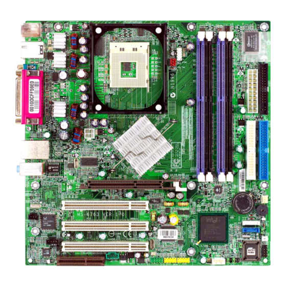
Mainboard Layout
4
Central Processing Unit: Cpu
Download this manual
865GM3/865PEM2 Series
MS-6763 (v1.X) M-ATX Mainboard
Version 1.0
G52-M6763X1-G22
i
Table of
Contents
Previous
Page
Next
Page
1
2
3
4
5
Advertisement
Table of Contents
Need help?
Do you have a question about the 865GM3 Series and is the answer not in the manual?
Ask a question
Questions and answers
Related Manuals for MSI 865GM3 Series
Motherboard MSI 848PM User Manual
M-atx mainboard (74 pages)
Motherboard MSI 848P Neo-V Series User Manual
Atx mainboard (61 pages)
Motherboard MSI 848P Neo-V Series Instruction Manual
Msi 848p neo-v motherboard: instruction manual (108 pages)
Motherboard MSI 865PE Neo2-P Platinum Edition User Manual
Ms-6728 (v2.x) atx mainboard (88 pages)
Motherboard MSI 865PE NEO2-LS - Motherboard - ATX User Manual
Ms-6728 (v1.x) atx mainboard (118 pages)
Motherboard MSI 865GM2-LS - Motherboard - Micro ATX User Manual
Ms-6743 (v1.x) micro atx mainboard (109 pages)
Motherboard MSI 865GVM3-V Instruction Manual
Msi 865gvm3-v motherboard: instruction manual (92 pages)
Motherboard MSI MS-7101 Instruction Manual
Msi ms-7101 motherboard: instruction manual (90 pages)
Motherboard MSI 865PE Neo3-V Series Instruction Manual
Msi 865pe neo3-v motherboard: instruction manual (80 pages)
Motherboard MSI 865PE Neo3-F User Manual
V3.x atx mainboard (110 pages)
Motherboard MSi 865PEM2 Series User Manual
V1.x m-atx mainboard (70 pages)
Motherboard MSI 865PE/G Neo2-P MS-6728 Manual
Ms-6728 (v2.x) atx mainboard (148 pages)
Motherboard MSI MS-7156 Instruction Manual
Msi ms-7156 motherboard: instruction manual (79 pages)
Motherboard MSI 865GVM Manual
(v1.x) micro atx mainboard (88 pages)
Motherboard MSI 865P Neo Manual
Atx mainboard (109 pages)
Motherboard MSI 865G Neo2 Manual
Atx mainboard (115 pages)
This manual is also suitable for:
865pem2 series
Ms-6763
Table of Contents
Print
Rename the bookmark
Delete bookmark?
Delete from my manuals?
Login
Sign In
OR
Sign in with Facebook
Sign in with Google
Upload manual
Upload from disk
Upload from URL


Need help?
Do you have a question about the 865GM3 Series and is the answer not in the manual?
Questions and answers