Table of Contents
Advertisement
Quick Links
Advertisement
Table of Contents

Related Manuals for MIMAKI JV33-130BS


Summary of Contents for MIMAKI JV33-130BS
- Page 1 MIMAKI ENGINEERING CO., LTD. URL: http: // www.mimaki. co. jp/ D201887-16...
-
Page 2: Table Of Contents
TABLE OF CONTENTS CAUTION ................vii DISCLAIMER OF WARRANTY ........vii Requests ................vii FCC Statement (USA) ............vii Interference to televisions and radios ......vii Foreword ................viii On This Operation manual ..........viii Features ................ix Safety Precautions ............xi Symbols ................xi CHAPTER 1 Before Use Moving this machine .......... - Page 3 Turning the power ON/OFF ........2-4 Turning the power ON ..........2-4 Turning the power OFF ..........2-5 Setting medias ............2-6 Useable medias ............2-6 Adjusting the head height ......... 2-6 Setting a roll media ........... 2-8 Take-up device ............2-13 Setting leaf media ...........
- Page 4 Setting cleaning while printing ......3-22 Setting media detection ........3-24 Other settings ............3-26 Initializing the settings .......... 3-28 Machine settings ........... 3-29 Setting the deodorize fan ........3-30 Setting Dryness feeding ..........3-31 Setting Stamp ............3-32 Change the operation condition of the room temperature .............3-33 When using 600 cc cartridge (firmware Ver.3.10 or older) ........3-34...
- Page 5 When not using for a long term (CUSTODY WASH) (firmware Ver.3.20 or older) ........4-14 When not using for a long term (firmware Ver. 3.30 or later) ........4-16 Cleaning heads and surroundings parts ....4-19 When Nozzle clogged after cleaning ....4-21 Filling up ink ............
- Page 6 CHAPTER 6 Appendix Machine specifications ........... 6-2 Ink specifications ............ 6-4 Sheet for inquiry ............. 6-5 Warning labels ............6-6 Function Flowchart ..........6-8...
-
Page 8: Caution
Operation of this equipment in a residential area is likely to cause harmful interference in which case the user will be required to correct the interference at his own expense. In the case where MIMAKI-recommended cable is not used for connection of this device, limits provided by FCC rules can be exceeded. -
Page 9: Foreword
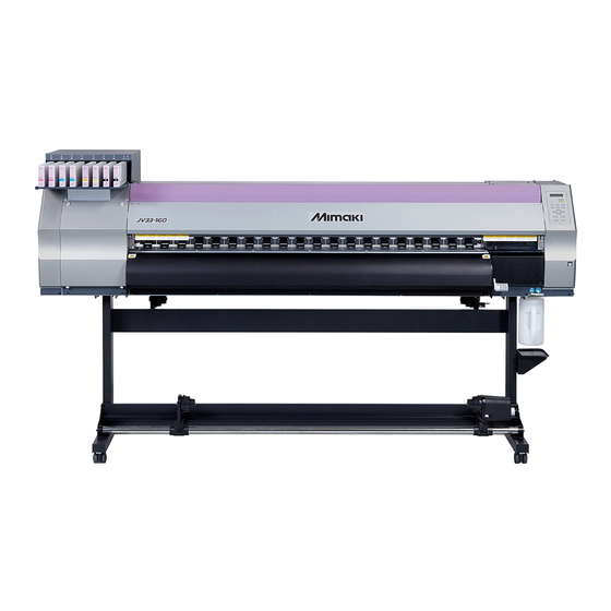
Foreword Congratulations on your purchase of MIMAKI color ink jet printer "JV33-130/160BS" . The JV33-130/160BS is a color ink-jet printer for high quality printing with solvent ink. On This Operation manual • This Operation manual is describing the operations and maintenance of "Color inkjet printer JV33-130/ 160BS"... -
Page 10: Features
Features The features of the machine are described below. Understanding them together with the operating instructions given in this manual will help you use the machine properly. High image quality and High-speed printing realized by the new generation printer head. Newly developed printer head, 1 head consisting of 1440 nozzles (180 nozzles x 8 lines), is adopted. - Page 11 Features Printing information can be checked The print length can be displayed on the LCD panel during printing and the information of printing con- ditions can be checked by printing it. High-speed interface The "USB 2.0" interface allows for high-speed data reception from the computer. Take-up Device permits printing over a long length Even a long sheet of media can be used, since the take-up device interlocked with the machine winds up the printed part of the sheet during printing.
-
Page 12: Safety Precautions
Safety Precautions Symbols Symbols are used in this Operation Manual for safe operation and for prevention of damage to the machine. The indicated sign is different depending on the content of caution. Symbols and their meanings are given below. Please follow these instructions as you read this manual. Examples of symbols Meaning Failure to observe the instructions given with this symbol can result in death or serious injuries to... - Page 13 Check first that the machine no longer produces smoke, and then contact your distributor or a sales office of MIMAKI for repair. • Never repair your machine by yourself since it is very dangerous for you to do so.
-
Page 14: Precautions In Use
MIMAKI. Note on maintenance • When cleaning the ink-station or the heads, make sure to wear the attached gloves. Further, when the solvent ink is used, it is necessary to wear the attached goggles. -
Page 15: Cautions And Notes
Handling of media • The machine does not operate with any ink other • Use media recommended by MIMAKI to ensure than the this machinegenuine ink. reliable, high-quality printing. • Do not use the this machine genuine ink with other •... - Page 16 Safety Precautions Warning Notes on maintenance • It is strongly recommended to use the machine in a room that is not dusty. Set the Refresh level 2 or 3 when the machine is to be used in an unfavorable environment. (P.3-27 "Setting of Refreshing") •...
- Page 17 CHAPTER 1 Before Use This chapter describes the items required to understand before use, such as name of each part of the machine or the installation procedures. Moving this machine ..... 1-2 Connecting cables ....... 1-10 Where to install this machine .... 1-2 Connecting USB2.0 interface cable 1-10 Working environmental temperature .
-
Page 18: Moving This Machine
500 mm or more or more 1000 mm or more JV33-130BS:3289 mm JV33-160BS:3538 mm Working environmental temperature Use this machine in an environment of 20 to 35°C to ensure reliable printing. Depending on the ambient temperature, the heater temperature may not rise to the set value. -
Page 19: Moving This Machine
If you move it by yourself, failure or damage may occur. Be sure to request your distributor or a sales office of MIMAKI to move this machine. • When moving this machine, take care not to give a significant impact on it. -
Page 20: Names Of Parts And Functions
Names of Parts and Functions Front Maintenance cover Front cover Open the cover in maintenance. Open the cover in setting of medias, taking of measures Even when the power switch is off, keep against jamming of medias or in maintenance inside the all covers closed. -
Page 21: Rear / Sides
Names of Parts and Functions Rear / Sides Clamp lever (rear) Interlocks with the clamp lever in the font of this machine. Pre-heater Preheats the media before printing. (Located inside the platen) Cleaning solution cartridge Set a dedicated Washings cartridge (optional). -
Page 22: Operation Panel
Operation Panel Use the operation panel to make settings for printing or operate this machine. Display CONSTANT lamp Displays the status of the Lights in green when the heater temperature machine, set items and errors. reaches the set temperature. HEAT lamp Lights in orange during heating up of the ACTIVE lamp heater. -
Page 23: Heater
Names of Parts and Functions Heater Pre-heater /Print heater / Post-heater are equipped on the platen. The Pre-heater is used for pre-heating of the media prior to printing to prevent rapid temperature changing. The Print-heater improves the image quality in printing. The Post-heater dries ink after printing. -
Page 24: Carriage
Carriage The carriage is provided with the ink heads for printing, the cutter unit for cutting off the sheet of media, etc. A lever is also provided to adjust the height of Head in 2 stages according to the thickness of media. ( P.2-6) Cutter blade and cutting line The carriage is provided with a cutter unit for cutting off the media that has been printed on. -
Page 25: Capping Station
Names of Parts and Functions Capping station • Be sure to wear the attached goggles in cleaning within the capping station to protect your eyes against ink. The capping station consists of the ink caps, the wiper for clean- ing the heads, etc. The ink caps prevent the nozzles in the ink heads from drying up. -
Page 26: Connecting Cables
Connecting cables Connecting USB2.0 interface cable Connect the PC and this machine with the USB2.0 inter- face cable. USB cable • Your RIP must be compatible with USB 2.0. • Contact a RIP maker near your location or our office when the USB2.0 interface is not attached to the PC. -
Page 27: Connecting The Power Cable
Connecting cables Removing USB memory If a USB memory module is inserted in the personal computer to which a JV33-BS machine is connected, click "Stop" in the "Safely Remove Hardware" window by following the instructions given there first and then remove the module. -
Page 28: Inserting Ink Cartridges
Inserting ink cartridges Insert an ink cartridges. Shake the ink cartridge as shown on the right. Insert the ink cartridge. • Insert the ink cartridge lengthwise directing the surface having IC chips to the left side. • Colors are displayed on the display as follows. Black: K, Cyanogen: C, Magenta: M, Yellow: Y Changing an ink cartridge... -
Page 29: Caution In Handling Of Ink Cartridges
• Do not shake ink cartridges violently. This may result in ink leakage from the ink cartridges. • Never refill the ink cartridges with ink. This may result in troubles. MIMAKI will not bear any responsibility for any damage caused by the use of the ink cartridges refilled with ink. -
Page 30: Media
Caution in handling of medias Pay attention to the followings for handling of medias. • Use media recommended by MIMAKI to ensure reliable, high-quality printing. Set the heater temperature to meet the characteristics of the media. • Set the temperature of the Pre-heater, Print heater and Post-heater according to the type and characteristics of the media used. -
Page 31: Menu Mode
Menu mode This machine has 4 modes. Each menu mode is described below. NOT-READY mode This is the mode in which the media has not been detected yet. The keys other than the key and the / key are effective. LOCAL mode Local mode is the mode for the drawing preparation state. - Page 32 1-16...
- Page 33 CHAPTER 2 Basic Operations The procedures from the ink and media preparation to drawing and the setting procedures are described. User type ........2-2 Preparing Heaters ......2-18 Set items registrable to User type ..2-2 Changing temperature settings of Using the registered user type ..
-
Page 34: User Type
User type Drawing of higher quality prints is available by making (setting of User type) the print set matching to the characteristics of media when this machine is used for drawing. On this machine, 4 types of User type 1 to 4 are settable. Set items registrable to User type For the registering procedures to User type (1 to 4), refer to P.3-2 . -
Page 35: Workflow
Workflow Turning the power ON/OFF Referring to "Turning the power ON/ OFF" ( P.2-4). Setting medias Referring "Setting medias" P.2-6). Preparing Heaters Referring to "Preparing Heaters" P.2-18). Test printing Referring to "Test printing" P.2-20). Drawing data Referring to "Drawing data" P.2-22). -
Page 36: Turning The Power On/Off
Turning the power ON/OFF Turning the power ON The machine is provided with the following two power switches. Main power switch : At the side of this machine. Keep it "ON" always. Power switch : Normally, use this switch to turn the power ON/OFF. The power switch lights in green when the power is ON and blinks in green when it is OFF. -
Page 37: Turning The Power Off
Turning the power ON/OFF Turning the power OFF Turn the power OFF by pressing the power switch located on the side of after using. Check the followings when the power is turned off. • If it is in receiving of data from the PC, or there is any data un-output. •... -
Page 38: Setting Medias
Setting medias Useable medias This machine can be used with roll media and leaf sheet media. For useable medias, refer to P.1-14 "Usable sizes of media". Adjusting the head height Adjust the head height according to the thickness of the media used. •... - Page 39 Setting medias Adjust the height-adjusting lever according to the media. • Adjust the position of the lever, referring to "For the adjusting lever and the range". • Set the height-adjusting lever to the highest stage or the lowest stage. Setting it to the intermediate height, a printing fault can result.
-
Page 40: Setting A Roll Media
Setting a roll media Set a roll media to the roll media hanger located on the back of this machine. • Take care not to drop the media on a foot or so when the media is set. It may cause an injury due to the media. -
Page 41: This Machine
Setting medias Move the roll holder to the roll setting position. Roll holder Set the base position Basis of roll holder within this range. 3 Inch Roll Media Roll Holder Set Position 2 Inch Roll Media Setting position of 3inch tube 3 Inch Roll Media Roll Holder Set Position... - Page 42 Insert the roll media in this machine. Pinch roller • The roll media can be smoothly inserted by slanting the media. (1) Pull the media out of the roll to the head of the platen. (2) Insert the media between the platen and the pinch roller.
- Page 43 Setting medias Hold the media with the media press gen- tly. • Set the media so that no media sticks out from the right end pinch roller to the right side. • When using a thick media, remove the media press from the media before printing.
- Page 44 Secure the media on the take-up device. P.2-13) (1) Feed the media up to the core of the roll media of the take-up device by pressing the key. (2) Fix the middle of the media with adhesive tape. (3) In the same manner, fix the left side and right side of the media.
-
Page 45: Take-Up Device
Setting medias Take-up device The take-up direction of media is selectable by using the switch of the take-up device. Lever in top position (REVERSE) : The take-up device winds the media with the printed side facing Lever in middle position (OFF) : The take-up device does not wind the media. -
Page 46: Setting Leaf Media
Setting leaf media Unlike roll media, leaf media does not need to be retained with the roll holders. Open the front cover. Front cover Raise the clamp lever. Clamp lever Insert the leaf media between the platen and the pinch rollers. •... - Page 47 Setting medias Press the key to select “LEAF” . MED I A S E L EC T RO L L < > L E A F The media detection is started. DE T EC T I NG MED I A NOW P L E A S E WA I T (1) The media width is detected.
-
Page 48: Changing The Printing Origin
Changing the printing origin The position of the printing origin can be changed. Moving the LED pointer to the changing position and deciding the position. In the local mode, OR I G I N SE T UP press the keys. 0 . - Page 49 Setting medias Typical setting position of printing origin The printing origin in the depth direction (X') is positioned at about 40 mm rearward from the cutting line. The printing origin in the scanning direction (Y') is positioned at 15 mm from the right end of the media. The value in the scanning direction (Y') can be changed using [MARGIN] in FUNCTION mode.
-
Page 50: Preparing Heaters
Preparing Heaters Changing temperature settings of Heater The set temperature of Heater can be changed and stored by [HEATER] of the setup mode. ( P.3-8) The adjusting procedures of the temperature set in the setup mode are described below. Set the Heater temperature according to the media used. •... -
Page 51: Confirming The Heater Temperature
Preparing Heaters Reference for the temperature set Glossy chloroeth- Type of media Tarpaulin ylene Set of the Pre-heater 35°C 35°C 35°C Set of the Print-heater 35°C 35°C 35°C Set of the Post-heater 50°C 50°C 50°C • Adjust it to suitable temperature depending on the media condition. •... -
Page 52: Test Printing
Test printing Perform the test printing to check if printing failures (blurring or missing) due to nozzle clogging or the like occur on the printed. Test printing • When a leaf media is used, set a larger media than the A4 size in longitudinal feeding. •... -
Page 53: Head Cleaning
Test printing Head cleaning Three head cleaning types are available. Select it depending on the result of pattern drawings. NORMAL: Select this if any line is missing. SOFT : When only head wiping is desirable. (in case of bent lines) HARD : Select this if inferior printing cannot be improved even by [NORMAL] or [SOFT] cleaning. -
Page 54: Drawing Data
Drawing data Starting the print • When a roll media is used, rewind the roll media by hands prior to printing so that it is set in the tightened condition. The loosened may result in failures of the image quality. Set the media. -
Page 55: Stopping The Print Temporarily
Drawing data Stopping the print temporarily Perform the following operations when stopping the print halfway. Press the key in printing. < L OCA L . 1 > [ # 0 1 ] w i d t h : 1 2 7 2 mm •... -
Page 56: Cutting A Media
Drawing data Cutting a media For a roll media, two ways are available to cut the media after printing is completed, as follows. • Pay attention so that printed surface does not touch to a floor or other printed surfaces when the media is cut. - Page 57 CHAPTER 3 Convenient use This section describes the operation procedures for using the machine more conveniently and each setting procedure. User type ..........3-2 Other settings........3-26 Initializing the settings ..... 3-28 Registering the drawing conditions together (Type registration) ....3-2 Machine settings .......
-
Page 58: User Type
User type Registering the drawing conditions together (Type registration) The drawing conditions are registered in each type (1-4). The most suitable drawing conditions are settable only by changing the type when replaced by a different type of media, if the drawing conditions that meet the media to be used have been registered in the type. Example of type registration Type 1 For Tarpaulin 1... -
Page 59: List Of Functions
User type List of functions This section describes the outline of each SET UP function registerable to the user type and the setting value. The underlined has been set when purchased. Function name Set value Outline Prints a pattern to correct the MEDIA COMP. - Page 60 User type Function name Set value Outline Sets the priority of settings (host / panel) Sets each item of the follow- ings individually when the indi- vidual setting is selected. • MEDIA COMP. • HEATER • PRINT MODE INDIVIDUALLY/ ALL HOST / PRIORITY ( P.3-18) •...
-
Page 61: Setting Media Compensation
Setting media compensation Correct the feeding rate of media after the type of media is replaced or the temperature of Heater is changed. If the correction value is not appropriate, stripes may appear on the print, thus resulting in a poor print. •... - Page 62 Press the key twice. [ 1 ] MED I A COMP . PR I N T S T AR T Print the compensation pattern by PR I N T I NG pressing the key. P L E A S E WA I T Check the compensation pattern then [ 1 ] MED I A COMP .
- Page 63 Setting media compensation When you need to correct the media feed during printing The media feeding amount can be corrected even in the remote mode or when printing image data. Press the key in the * REMOT E . 1 * [ # 0 1 ] remote mode.
-
Page 64: Changing The Set Value Of Heater
Changing the set value of Heater Rough guide for temperature setting Type of media Tarpaulin Pre-heater 35°C 35°C 35°C Print-heater 35°C 35°C 35°C Post-heater 50°C 50°C 50°C • Adjust each heater temperature to a value best suited to the media conditions. Changing temperature settings of Heater Set each item of [SET TEMP] and [SET TIME] . - Page 65 Changing the set value of Heater Press the key. [ 1 ] MED I A COMP . < e n t > Select [HEATER] by pressing the [ 1 ] keys. HE A T ER < e n t > Press the key twice.
-
Page 66: Adjusting Suitable Temperature Adjustment
Adjusting suitable temperature adjustment This section describes the procedure for setting the heater temperatures properly. The proper heater temperatures depend on the media type and ambient temperature. Set temperatures that are appropriate to the media. For non-coated media or media on which ink is slow to dry, set the heater tem- peratures so that the ink fixing and drying characteristics will be improved. -
Page 67: In Case The Heater Temperature Is Too Low
Changing the set value of Heater In case the heater temperature is too low This may result in printing failures such as beading or banding if the heater temperature or the ink accept- able amount (the ink limit) is too low. Beading is a phenomenon that adjacent dots attract each other and join. -
Page 68: Setting Print Mode
Setting print mode Upon the setting of the print mode, set each item for printing as follows. • Print quality (DRAFT) : Setting the print quality in the DRAFT mode (Resolution in the scanning direction: 540dpi) • Print quality (FINE) : Setting the print quality in the FINE mode (Resolution in the scanning direc- tion: 720dpi) •... - Page 69 Setting print mode When changing the details of printing quality at each resolution. [ 1 ] DRA F T QUA L I T Y Select the resolution by pressing the 5 4 0 x 7 2 0 < e n t > key.
-
Page 70: Setting Scanning Direction
Setting scanning direction Perform operations up to P.3-12 the [ 1 ] PR I N T MODE step 5. DRA F T QUA L I T Y < e n t > Select [SCAN DIRECTION] by pressing [ 1 ] PR I N T MODE keys. -
Page 71: Setting Logical-Seek
Setting print mode Setting Logical-seek The motion of Head varies depending on the set of Logical-seek. UNI-DIRECTIONAL BI-DIRECTIONAL Movement of heads when LOGICAL seek is OFF Movement of heads when UNI-DIRECTIONAL BI-DIRECTIONAL LOGICAL seek is ON Perform operations up to P.3-12 the [ 1 ] PR I N T MODE step 5. -
Page 72: Setting Drying Time
Setting drying time Upon the setting of drying time, set each item for ink drying as follows. • SCAN : Set the time to wait for ink drying after each pass. During bidirectional printing, the machine stops temporarily after every scanning back and forth. •... -
Page 73: Setting Margins
Setting margins Set a non-printing area along the right and left edges of the media. The offset value against the standard margin 15mm is set hereupon. Press the key in the local F UNC T I ON mode. S E T UP <... -
Page 74: Setting Priority
Setting Priority For the following items, the priority is selected either the setting by the machine (by the panel) or the setting by the PC (by the host). Items to be selected : MEDIA COMP. / HEATER / PRINT MODE / INK LAYERS / DRYING TIME / AUTO CUT / PRE-FEED / MARGIN / COLOR PATTERN / REFRESH / VACUUM / Feed SPEED LEVEL Press the... - Page 75 Setting Priority Select either “HOST” or “PANEL” by [ 1 ] PR I OR I T Y pressing the keys. MED I A COMP . ANE L Press the key. • You can also press keys to move between items. Be sure to press the key to register the setting.
-
Page 76: Setting Auto Cleaning
Setting Auto cleaning The machine is settable so that the head cleaning is automatically carried out when printing is completed for the set length. At the completion of printing, the machine counts the length printed after the previous head cleaning and performs the cleaning automatically if required. - Page 77 Setting Auto cleaning Select “ON” by pressing the [ 1 ] AU TO CRE AN I NG keys. S E T UP : ON • Proceed to the step 9 when “OFF” is selected. Press the key. I N T ERV A L : T Y P E 0 0 0 mm : NORMA L...
-
Page 78: Setting Cleaning While Printing
Setting cleaning while printing Set it whether the head cleaning is carried out automatically during printing or not. Upon cleaning during printing, set the cleaning interval to the length printed. The printing is interrupted each in the set length and the head cleaning is carried out automatically. Press the key in the local F UNC T I ON... - Page 79 Setting cleaning while printing Press the key. Press the key several times to end. • This function does not operate when ink near-end occurs. Solve the ink near-end, referring to P.1-12. • Depending on the conditions of the heads, etc., the defective printing could not be recovered even performing this function.
-
Page 80: Setting Media Detection
Setting media detection Set the method for detecting a media when the media is set and the detecting type when the media is cut. Press the key in the local F UNC T I ON mode. S E T UP <... - Page 81 Setting media detection Press the key. [ 1 ] MED I A DE T EC T DE T EC T : BOT H EDGE Select the set value by pressing the keys. • Set value : BOTH EDGE / LEFT EDGE / RIGHT EDGE / NONE Press the key.
-
Page 82: Other Settings
Other settings Change the setting according to the use. Press the key in the local F UNC T I ON mode. S E T UP < EN T > Press the key. S E T UP S E L EC T : T Y P E . -
Page 83: List Of Settings
Other settings List of Settings The underlined has been set when purchased. Item Outline Set value Setting of Media Corrects the feeding rate of media Refer to P.3-5 compensation Setting Heater temperature Setting of Heater Refer to P.3-8 Setting Heater standby time and OFF time Setting Print quality Setting of Printing mode... -
Page 84: Initializing The Settings
Initializing the settings Initialize the settings to the conditions that have been set when purchased. (Set resetting) The set resetting can be executed per type. Press the key in the local F UNC T I ON mode. S E T UP <... -
Page 85: Machine Settings
Machine settings It is each type of setting for using this machine more comfortably. [MACHINE SETUP] and [MACHINE SETUP2] are available in this machine. The following items are settable in MACHINE SETUP 1, 2. Item Outline Set value 0 ~ 120 ~ 240min/ Setting the time until the rotation of the exhaust STOP TIME DEODORIZE... -
Page 86: Setting The Deodorize Fan
Setting the deodorize fan The fan operates during printing, and operates according to the set of [STOP TIME] from the completion of printing. Upon the setting of the deodrize fan, two items are settable as follows. • STOP TIME : Setting the time from the completion of printing until the fan operation is interrupted. •... -
Page 87: Setting Dryness Feeding
Machine settings Setting Dryness feeding Setting whether feeding for drying a media is performed after the completion of printing or not. Press the key in the local F UNC T I ON mode. S E T UP < EN T > Select [MACHINE SETUP] by pressing F UNC T I ON keys. -
Page 88: Setting Stamp
Setting Stamp Set whether information such as the drawing conditions or the date printed is output after the completion of printing or not. Press the key in the local F UNC T I ON mode. S E T UP < EN T > Select [MACHINE SETUP] by pressing F UNC T I ON keys. -
Page 89: Change The Operation Condition Of The Room Temperature
Machine settings Change the operation condition of the room temperature If you print in the status that the temperature of the place in which the machine has installed (room temper- ature) is out of the usable temperature range, ink discharging defect or changing color may occur, and it adversely affects the printing quality. -
Page 90: When Using 600 Cc Cartridge (Firmware Ver.3.10 Or Older)
When using 600 cc cartridge (firmware Ver.3.10 or older) Requisite for the 600 cc cartridge Eco Case The 600 cc ink pack and the attached ink chip are put in the eco case and used. 600 cc Ink Pack This is referred to as "600 cc cartridge" in this manual. Ink Chip To calculate the remaining ink quantity, input the weight of the eco case and the 600 cc cartridge into this machine. - Page 91 Machine settings When using 600 cc cartridge for the first time When the 600 cc cartridge is set in the slot of the ink station, the weight registration function of the eco case automatically starts. Measure the weight of the eco case. •...
- Page 92 When the eco case weight is changed When the case weight is changed by replacing the eco case, register the weight of the eco case in the fol- lowing procedures. In the local mode, press the F UNC T I ON key.
- Page 93 Machine settings Press the key. CAR T . S l o t s e l e c t 1 . 3 . . 7 . • The slot selection screen is displayed again. • When you want to register the weight of another slot continuously, repeat the Step 6 to select a slot.
- Page 94 When [Ink Level] is displayed If quantity of the remaining 600 cc ink becomes low, a warning [Ink Level] appears. To use the ink remaining in the ink pack, input the 600 cc cartridge weight displaying the warning. • This function is only available for the 600 cc cartridge displaying [Ink Level] warning. •...
- Page 95 Machine settings Press the key. I n k L e v e l S e t . . C ..0 5 5 5 g OK ? Press the key. • Return to the local mode or the remote mode. ...
- Page 96 Inputting weight of the cartridge after initial ink filling When the initial ink charging ( P.4-24) was finished after [DISCHARGE & WASH], the screen to input the weight of the 600cc cartridge is displayed. • This machine calculates the available quantity of remaining ink from the weight of the 600 cc cartridge input in this machine.
- Page 97 Machine settings Error when performing maintenance function When performing the maintenance function such as the head cleaning or the ink filling for the 600 cc car- tridge, selected functions can be performed if the quantity of remaining ink is enough to execute the func- tion, even if the ink near end occurs.
-
Page 98: When Using 600 Cc Cartridge (Firmware Ver.3.20 Or Later)
When using 600 cc cartridge (firmware Ver.3.20 or later) Requisite for the 600 cc cartridge Eco Case The 600 cc ink pack and the attached ink chip are put in the eco case and used. 600 cc Ink Pack This is referred to as "600 cc cartridge" in this manual. Ink Chip To calculate the remaining ink quantity, input the weight of the eco case and the 600 cc cartridge into this machine. - Page 99 Machine settings When using 600 cc cartridge for the first time When the 600 cc cartridge is set in the slot of the ink station, the weight registration function of the eco case automatically starts. Measure the weight of the eco case. •...
- Page 100 When the eco case weight is changed When the case weight is changed by replacing the eco case, register the weight of the eco case in the fol- lowing procedures. In the local mode, press the F UNC T I ON key.
- Page 101 Machine settings Press the key. CAR T . S l o t s e l e c t 1 . 3 . . 7 . • The slot selection screen is displayed again. • When you want to register the weight of another slot continuously, repeat the Step 6 to select a slot.
- Page 102 When [Ink Level] is displayed When quantity of the remaining 600 cc ink becomes low, a warning [Ink Level] appears. Enter the weight of the cartridge with the Ink Level Set function. • This machine recalculates usable amount of remaining ink by entering the weight of the 600 cc cartridge.
- Page 103 Machine settings Press the key. I n k L e v e l S e t . . C ..0 5 5 5 g OK ? Press the key. • Usable amount of remaining ink is recalculated. •...
- Page 104 Inputting weight of the cartridge after initial ink filling When the initial ink charging ( P.4-24) was finished after [DISCHARGE & WASH], the screen to input the weight of the 600cc cartridge is displayed. • This machine recalculates usable amount of remaining ink by entering the weight of the 600 cc cartridge.
- Page 105 Machine settings Error when performing maintenance function When performing the maintenance function such as the head cleaning or the ink filling for the 600 cc car- tridge, selected functions can be performed if the quantity of remaining ink is enough to execute the func- tion, even if the ink near end occurs.
-
Page 106: Setting Test Draw Arrange
Setting Test draw arrange You can set the deployment direction of the test pattern to be printed when performing test printing repeat- edly. : when the setting value is “FEED DIR.” : when the setting value is “SCAN DIR.” Media feed direction Press the key in the local F UNC T I ON... - Page 107 Machine settings Press the key. Press the key several times to end. 3-51...
-
Page 108: Setting Confirmation Feeding
Setting confirmation feeding Set whether media feeding is performed for checking the result after test printing or not Press the key in the local F UNC T I ON mode. S E T UP < EN T > Select [MACHINE SETUP 2] by pressing F UNC T I ON keys. -
Page 109: Setting Time
Machine settings Setting time Press the key in the local F UNC T I ON mode. S E T UP < EN T > Select [MACHINE SETUP 2] by pressing F UNC T I ON keys. MACH I NE S E T UP 2 < EN T > Press the key. -
Page 110: Setting Unit
Setting Unit Set a unit of measurement to be used in the machine. Press the key in the local F UNC T I ON mode. S E T UP < EN T > Select [MACHINE SETUP 2] by pressing F UNC T I ON keys. -
Page 111: Setting Machine Name
Machine settings Setting Machine name Set a machine name (machine No.) for recognizing each machine when plural machines are connected through USB2.0 interface. Press the key in the local F UNC T I ON mode. S E T UP < EN T > Select [MACHINE SETUP 2] by pressing F UNC T I ON keys. -
Page 112: Setting Key Buzzer
Machine settings Setting Key buzzer Set a buzzer sound of the time when a key is pressed. Press the key in the local F UNC T I ON mode. S E T UP < EN T > Select [MACHINE SETUP 2] by pressing F UNC T I ON keys. -
Page 113: Extension Of Ink Expiry Month
Extension of Ink Expiry Month Ink expiry month can be extended for six months from the expired month. When used without extension, ink becomes unusable after two months of the expiry month. Extension of Ink Expiry Month The following setting or confirmation screen appears when the power of this machine is turned on, or when expired ink cartridge is set. -
Page 114: When A Cartridge Extended The Expiry Month Is Set
Extension of Ink Expiry Month When a cartridge extended the expiry month is set When a cartridge extended the expiry month is set and the power is turned on, or when a cartridge extended the expiry month is set to this machine, the following screen appears. E X P I RED I NK I N US E PRE S S [ EN T ] alternately... -
Page 115: Switch Setting Of Ink Supply Path
Switch Setting of Ink Supply Path For the ink supply, condition of the ink cartridge to be used first by the double-cartridge automatic switching function can be selected. This setting is only available for 4-color set. • When expired ink cartridge is set, the expired cartridge is used first regardless of the setting below. - Page 116 Switch Setting of Ink Supply Path When both ink cartridge and MBIS are used When both an ink cartridge and the optional bulk ink system (MBIS) are set in the supply paths of the same color for 4-color ink set, you can select the ink to be used first. •...
-
Page 117: Confirming Machine Information
Confirming machine information The machine information of the machine is confirmable. Confirmable items of the machine information are as follows. Item Description Displays the history of errors and warnings. ERROR HISTORY Using the key, the errors and warnings can be displayed one by one in the order of occurrence. - Page 118 Confirming machine information For the information displayed This section describes the way to read the information displayed. ERROR HISTORY MAINTE. HISTORY Displaying the occur- Displaying the con- ERROR H I STORY [ 0 1 ] 1 2 . 1 0 . 1 0 1 2 : 1 5 rence date tents of maintenance...
- Page 119 CHAPTER 4 Routine Maintenance This section describes the items required to use this machine more comfortably, which are the procedures of ink replacing, cleaning or the like. Maintaining..........4-2 Preventing nozzle clogging while Precautions in cleaning ......4-2 power-off ..........4-28 Notes on cleaning solution ....4-2 Setting refreshing interval in Sleep Cleaning exterior surfaces .....4-3...
-
Page 120: Maintaining
Maintaining Be sure to perform maintenance of the machine periodically or whenever necessary so that the machine can be used with its inherent accuracy for a long time. Precautions in cleaning Pay attentions to the following items when the machine is maintained. •... -
Page 121: Cleaning Exterior Surfaces
Maintaining Cleaning exterior surfaces If exterior surfaces of the machine is stained, dampen a soft cloth with water or a neutral detergent diluted with water, squeeze it and wipe the surfaces with the cloth. Cleaning the platen On the platen, it is easy to become dirt due to lint, paper dust or the like caused by cutting medias. For a conspicuous stain, wipe it off with a soft-hair brush, a dry cloth, a paper towel or the like. -
Page 122: Cleaning The Media Sensor
Maintaining Cleaning the media sensor A media sensor is located at the platen on the backside. It may cause misdetection of media when dust or the like is accumulated on the sensor. Using a cotton swab, clean the surface of the sensor of dust and dirt. When cleaning the sensor on the lower surface of the head is cleaned, move the carriage to the left end by the operations of step 1 of P.4-16 "Cleaning the heads and their surrounding parts", and then clean it. -
Page 123: Maintaining Capping Station
Maintaining Capping station Maintain Ink cap, Wiper or the like, which are located in the capping station. [ST.MAINTENANCE] The ink cap and wiper function respectively as follows. • Wiper : Wiping ink sticking to the head nozzle off. • Ink cap : Preventing the head nozzle from clogging due to drying. As the machine is used, the wiper and ink caps gradually become stained with ink and dust. - Page 124 Wiper Clean the wiper and bracket. • Wipe ink sticking to the wiper and the bracket off with a clean stick dipped in the cleaning solution. Bracket Clean the wiper slider. • Wipe ink sticking to the wiper slider off with a clean stick dipped in the cleaning solution.
-
Page 125: Replacing The Wiper
• The wiper to be newly installed is available as an option. Order it from your dealer or a sales office of MIMAKI. • Do not select [WIPER EXCHANGE] at any time other than when the wiper is to be replaced.Once it is selected, the number of wiper operations that is counted in the machine... -
Page 126: Before Washing Ink Discharge Passage
Before washing ink discharge passage Before washing ink discharge passage ([PUMP TUBE WASH], [NOZZLE PROTECT] (firmware Ver. 3.30 or later)), it is necessary that maintenance washing liquid has been filled in the tube. • When the following messages are indicated, check the waste ink tank, and then operate it, referring to P.4-40 "If Waste ink tank confirming message is displayed"... - Page 127 Maintaining Capping station Discharging Cleaning solution Perform the following operations to discharge the cleaning solution within the tube. Select [HD.MAINTENANCE] of the maintenance menu. (1) Press the key in the local mode. (2) Select [MAINTENANCE] by pressing the keys then press the key.
-
Page 128: Washing Of Head Nozzle
Washing of Head nozzle Perform cleaning of the nozzles in the heads to prevent them being clogged with coagulated ink. Is [NEAR END] or [INK END] displayed ? Make sure the • The cleaning solution or ink is absorbed in washing. followings in At this time, washing is unable to operate if the ink end or near-end is detected. - Page 129 Maintaining Capping station Press the key then fill the cap with the cleaning solution. • The cleaning solution is applied by drops when is pressed. • When the is pressed again, drops stop. • Repeat the drops several times to fill the cap with the cleaning solution just before the solution over- flows from the cap.
-
Page 130: Cleaning The Ink Discharge Passage (Pump Tube Wash)
Cleaning the ink discharge passage (PUMP TUBE WASH) Perform washing of the ink discharge passage (the pump tube) periodically to prevent ink from clogging due to the coagulation of ink within the ink discharge passage. • When the following messages are indicated, check the waste ink tank, and then operate it, referring to P.4-40 "If Waste ink tank confirming message is displayed"... - Page 131 Maintaining Capping station Close the front cover and press the * B e i n g I n i t i a l i z e d * key. P L E A S E WA I T • It returns to the local mode after the idle absorbing <...
-
Page 132: When Not Using For A Long Term (Custody Wash) (Firmware Ver.3.20 Or Older)
When not using for a long term (CUSTODY WASH) (firmware Ver.3.20 or older) When the operation of the machine is to be suspended for a week or more, use the [CUSTODY WASH] function to clean the nozzles in the heads and the ink discharge passage. After the cleaning, store the machine properly. - Page 133 Maintaining Capping station Press the key. F i l l t h e l i q u i d COMP L E T ED ( NE X T ) : e n t Press the key to fill the cap with the cleaning solution.
-
Page 134: When Not Using For A Long Term (Firmware Ver. 3.30 Or Later)
When not using for a long term (firmware Ver. 3.30 or later) When the operation of the machine is to be suspended for 24 hours or more, use the NOZZLE PROTECT function to protect the nozzle surface. This function is available for the firmware Ver. 3.30 or later. Execute the NOZZLE PROTECT function Has maintenance washing liquid been filled? •... - Page 135 Maintaining Capping station Executes the NOZZLE PROTECT function automatically You can set the status to enter the nozzle protection automatically (auto-execute function of NOZZLE PRO- TECT) in case the device is not used for a certain amount of time. In the nozzle protection status, NOZZLE PROTECT can be automatically executed regularly. To use the auto-execute function of NOZZLE PROTECT, set the following items.
- Page 136 Maintaining Capping station Press the key. A u t o N Z L . PROT EC T ON T i me By pressing the keys, set the A u t o N Z L . PROT EC T time length until the NOZZLE PROTECT ON T i me is executed.
-
Page 137: Cleaning Heads And Surroundings Parts
Cleaning heads and surroundings parts Take great care, especially during cleaning, not to damage the heads, which employ very precise mecha- nisms. Using a clean stick, rub off the gelatinous ink that may be adhering to the lower part of the slider and surrounding parts of the heads. - Page 138 Cleaning heads and surroundings parts Press the key after the clean- C l o s e a c o v e r ing. Close the maintenance cover then ( COV ER OP EN ) press the key. PRE S S < EN T > K E Y •...
-
Page 139: When Nozzle Clogged After Cleaning
When Nozzle clogged after cleaning When the nozzle clogging is not improved even after the head cleaning ( P.2-21) or the head nozzle washing ( P.4-10), execute two functions as follows. FILL UP INK • Supplies ink to correct nozzle clogging. •... -
Page 140: Discharge & Wash
DISCHARGE & WASH Discharge ink from the heads, dampers and ink tubes, and then wash them. • When the following messages are indicated, check the waste ink tank, and then operate it, referring to P.4-40 "If Waste ink tank confirming message is displayed" according to the situa- tion. - Page 141 When Nozzle clogged after cleaning Remove the cleaning solution car- * D I SCHARGE * tridge. 0 0 : 0 0 • The ink left in the head or tube is discharged to the waste ink tank. • The right display on the right is displayed after dis- S e t : Wa s h i n g C a r t r i d g e charging.
-
Page 142: Initial Ink Fill Up
• You cannot change the current ink set to other ink set yourselves. • If you want to change the ink set, contact sales office of MIMAKI. Press the key. B S * - 4 c o l o r... - Page 143 When Nozzle clogged after cleaning Set an ink cartridge to the ink station. B S * - 4 c o l o r - - C - Y - K K • When the ink cartridge is set, filling is automati- F I L L I NG UP cally started.
-
Page 144: If Dots Misalign
If dots misalign When the thickness of the media, the height of the head, or the type of the ink used is changed, follow the steps below and adjust the ink drop position for Bi-directional (Bi) printing to print properly. Example of Pattern printing Output The dots at the fourth position counted from the zero... - Page 145 If dots misalign As the same as the step 4, correct the dot position of the from pat- tern 2 then press the key. Press the key several times to end. 4-27...
-
Page 146: Preventing Nozzle Clogging While Power-Off
Preventing nozzle clogging while power-off Even while the power switch is off, the machine starts periodically and executes various functions to prevent nozzle clogging. [SLEEP SETUP] includes the following functions. Function name Descriptions Set the interval at which refreshing operation is to be performed REFRESH periodically. -
Page 147: Setting Tube Washing Interval In Sleep Mode
Preventing nozzle clogging while power-off Setting tube washing interval in Sleep mode Set the interval at which cleaning of the caps and pump tubes is to be performed using the cleaning solution during sleep mode. Select [SLEEP SETUP] of the maintenance menu. (1) Press the key in the local mode. -
Page 148: Setting Cleaning Interval In Sleep Mode
Preventing nozzle clogging while power-off Setting cleaning interval in Sleep mode This function is to be executed instead of TUBE WASH after the cleaning solution has been used up. Set the cleaning type and the interval at which cleaning operation is to be performed during sleep mode. Select [SLEEP SETUP] of the maintenance menu. -
Page 149: Setting Routine Operations
Setting Routine operations Troubles such as ink clogging or the like are preventable by performing each periodical operation in the condition of the power ON. (Initial setting) The [ROUTINE SETUP] function is available for the following items : Function name Descriptions While printing, the nozzle surface is wiped with a certain interval to remove ROUTINE WIPING... - Page 150 Press the key. ROU T I NE W I P I NG SCAN COUN T Set the number of scans by pressing ROU T I NE W I P I NG keys. SCAN COUN T • Set value : 0 to 9990 times •...
-
Page 151: Setting Refreshing Interval In Standby Mode
Setting Routine operations Setting Refreshing interval in Standby mode Set the interval at which refreshing operation is to be performed periodically. Select [ROUTINE SETUP] of the maintenance menu. (1) Press the key in the local mode. (2) Select [MAINTENANCE] by pressing the keys then press the key. -
Page 152: Setting Pump Tube Washing Interval In Standby Mode
Setting Pump tube washing interval in Standby mode Perform the pump tube washing periodically to prevent ink from clogging due to the coagulation of ink, which occurs within the tube. • This function is operable only under the condition that the machine is left in the following dis- plays. -
Page 153: Setting Cleaning Interval In Standby Mode
Setting Routine operations Setting Cleaning interval in Standby mode This function is to be executed instead of TUBE WASH after the cleaning solution has been used up. Set the cleaning type and the intervals at which cleaning operation is to be performed. •... - Page 154 Setting Routine operations Press the key several times to end. 4-36...
-
Page 155: Other Maintenance Functions
Other maintenance functions Changing the warning time of wiper replacement The wiper is consumable. The heads are easily soiled in a dusty environment. The heads cannot be cleaned adequately with a curled or worn wiper. Setting the wiper level so that a warning for the wiper replacement period is indicated earlier than the stan- dard depending on the operating environment. -
Page 156: Setting The Media Remaining Display
Setting the media remaining display Set the media remaining amount display. When the media remaining The media remaining amount is displayed in the remote mode. amount display is turned to (The print length is displayed when a leaf media is used.) "ON"... - Page 157 Other maintenance functions Print the media remaining amount You can print the current media remaining amount. • Set [MEDIA RESIDUAL] to “ON”. ( P.4-38) • When changing the media, it is recommended to print the remaining amount to the currently used media.
-
Page 158: If Waste Ink Tank Confirming Message Is Displayed
If Waste ink tank confirming message is displayed Waste ink which was used for cleaning the heads and other parts, gathers in the waste ink tank. Upon the machine, the ink discharging amount is counted by accumulated counting then a message for suggesting the check is displayed when it reaches a certain amount. - Page 159 Other maintenance functions Check message in Local mode The right message is displayed. < L OCA L . 1 > [ # 0 1 ] C h e c k w a s t e i n k <MN T > Check the waste ink tank, and then replace the waste ink tank P.4-42) if required.
- Page 160 Replacing waste ink tank When the right message is displayed, check the waste ink tank < L OCA L . 1 > [ # 0 1 ] immediately, and then replace it according to the condition. C h e c k w a s t e i n k <MN T >...
- Page 161 Other maintenance functions Close the waste ink tank guard. • Hook the waste ink tank guard in a hole of the machine then lock it. Hole Hook Select [Ink Tank Exchange] of the maintenance menu. (1) Press the key in the local mode. (2) Select [MAINTENANCE] by pressing the keys then press the key.
-
Page 162: Replacing The Cutter Blade
Replacing the cutter blade The cutter blade is consumable. When the cutter blade gets dull, replace it with a new one (SPA-0107). • The blade is sharp. Be careful not to hurt yourself or anyone else. • Keep the cutter blades away from the reach of children. Be sure to dispose of the worn-out cutter blades according to the applicable national and local laws and regulations. - Page 163 Replacing the cutter blade Close the front cover. Press the key. • The machine returns to LOCAL mode. 4-45...
- Page 164 4-46...
- Page 165 CHAPTER 5 Troubleshooting This section describes the corrective measures to be taken for a phenomenon suspected to be trouble and the procedures to clear the error number displayed on the LCD. Troubleshooting ............5-2 Power does not turn on ............5-2 The machine does not start printing ........5-2 Media get jammed / media is soiled ........5-3 [HEAT] or [CONSTANT] LED does not light up ....5-3...
-
Page 166: Troubleshooting
Troubleshooting Take appropriate actions as described below before taking the trouble as a failure. If still the problem is not solved after troubleshooting, contact your dealer or an office of MIMAKI. Power does not turn on In most cases, this is due to improper connection of the power cable for the machine or computer. Check that the power cable is connected properly. -
Page 167: Media Get Jammed / Media Is Soiled
Troubleshooting Media get jammed / media is soiled Media jamming or stained media is considered to be due to the use of an unsuitable media or improper set- ting of media. Is a recommended media used ? Use recommended media. Avoid using any media with curls or bent Is the media not curled or bent ends ? ends. -
Page 168: Image Quality Is Poor
This section describes the corrective actions to be taken in case the image quality is not satisfactory. Take remedy for particular problems with image quality. If the remedy does not work, contact your dealer or an office of MIMAKI. Phenomenon Measures (1) Execute the head cleaning. -
Page 169: Ink Cartridge Warning Appears
• Once cartridge trouble is displayed, do not leave the ink cartridge without replacing it for a long time; otherwise, the machine will lose the nozzle clogging prevention function. If nozzles are clogged, the machine must be repaired by MIMAKI's service engineer. Displaying the description of ink cartridge trouble The contents of cartridge error are confirmable by the following operations. -
Page 170: Warning / Error Messages
Warning / Error Messages If some trouble occurs, the buzzer sounds and the display shows a corresponding error message. Take an appropriate remedy for the displayed error. Warning messages Message Cause Solution Check the front cover and maintenance covers. The front cover or the maintenance C l o s e a c o v e r . -
Page 171: Warning Messages
- - - - Y Y K K The ink cartridge is not MIMAKI Replace the cartridge generating the NON - OR I G I N A L I N K genuine. - Page 172 Message Cause Solution Remove and weigh the 600cc cartridge, I N K L E V E L ( 6 0 0 c c ) 600cc ink is low. then set it again. (See P.3-46 “When [Ink - - - - - - - - Level] is displayed”.) Replace the waste ink tank then execute...
-
Page 173: Error Messages
Warning / Error Messages Error messages When an error message is displayed, eliminate the error according to the chart below. If the same error message appears again, contact your dealer or an office of MIMAKI to call for service. Message Cause... - Page 174 Message Cause Solution Turn off the main power to the machine Any parameter outside the range of and turn it on after a while. * * * * * E R ROR 1 1 * * * * * acceptable numeric values was If the same error message appears again, P A R AME T E R E R ROR received.
- Page 175 Warning / Error Messages Message Cause Solution Turn off the main power to the machine and turn it on after a while. An error occurred in the wiper con- * * * * * E R ROR 4 6 * * * * * If the same error message appears again, trol.
- Page 176 Warning / Error Messages Message Cause Solution Turn off the main power to the machine An error was detected during scan- * * * * E R ROR 2 5 0 * * * * and turn it on after a while. ning operation.
- Page 177 CHAPTER 6 Appendix This section attaches a list of the specifications and a list of the functions of this printer. Machine specifications ..........6-2 Ink specifications ............6-4 Sheet for inquiry ............6-5 Warning labels ............. 6-6 Function Flowchart ............. 6-8...
-
Page 178: Machine Specifications
Machine specifications Item JV33-130BS JV33-160BS Method Drop-on-demand piezoelectric print heads Print head Specification 1 head 720 x 540dpi 540 or 720 x 720dpi 540 x 900dpi Drawing mode (scan x feed) 540 or 720 x 1080dpi 720 x 1440dpi 1440 x 1440dpi... - Page 179 Machine specifications Item JV33-130BS JV33-160BS Interface USB 2.0 Command MRL- III during standby Less than 58 dB (FAST-A, Front & Rear & Left & Right 1 m) during continu- Less than 65 dB Noise ous printing during discontin- Less than 70 dB...
-
Page 180: Ink Specifications
Ink specifications Item When solvent ink is used Supply Dedicated ink cartridges Black ink cartridge Cyan ink cartridge Color Magenta ink cartridge Yellow ink cartridge Ink capacity 600cc per cartridge • BS* Ink 1 year from the date of manufacture Shelf life (at room temperature) Within three months after opening the package... -
Page 181: Sheet For Inquiry
Sheet for inquiry Use this sheet for troubles and abnormal functions of the machine. Fill in the following necessary items, and then fax the sheet to our sales office. Company name Person in charge Telephone number machine model Operating OS Machine information Error message Contents of inquiry... -
Page 182: Warning Labels
Warning labels Warning labels are stuck on the machine. Be sure to fully understand the warning given on the labels. If a warning label is illegible due to stains or has come off, purchase a new one from a distributor or our sales office. - Page 183 Warning labels Reorder Label M901549 M903239 M903330 M903405 M904810...
-
Page 184: Function Flowchart
Function Flowchart < L OCA L . 1 > [ # 0 1 ] w i d t h : * * * * mm OR I G I N S E T UP OR I G I N S E T UP 0 . - Page 185 Function Flowchart MED I A RE S I DUA L DRAW < E N T > Only when [MEDIA RESIDUAL] is “ON” NON - OR I G I NA L I NK WRONG I NK I C K i n d o f I N K M - C - - - - K...
- Page 186 < L OCA L . 1 > [ # 0 1 ] F UNC T I ON SETUP w i d t h : * * * * mm S E T UP < E N T > F UNC T I ON MAINTENANCE MA I N T ENANCE <...
- Page 187 Function Flowchart To P.6-12 To P.6-18 To P.6-24 To P.6-25 To P.6-26 6-11...
- Page 188 SETUP S E T UP [ 1 ] [ 1 ] MED I A COMP . S E L EC T : T Y P E . 1 MED I A COMP . < e n t > PR I N T S T AR T TYPE.2 TYPE.3 TYPE.4...
- Page 189 Function Flowchart End the P L E A S E WA I T [ 1 ] MED I A COMP . printing PR I N T I NG V A L UE -255 to 255 PR T POS T 5 ° C 4 0 °...
- Page 190 From P6-12 [ 1 ] [ 1 ] I NK L A Y E RS I NK L A Y ERS < e n t > S E T UP 1 to 9 [ 1 ] SCAN : D r a w . END DRY I NG T I ME <...
- Page 191 Function Flowchart 6-15...
- Page 192 From P6-14 When INDIVIDUALLY is selected [ 1 ] [ 1 ] P R I OR I T Y PR I OR I T Y < e n t > S E T UP ND I V I DUA L L Y INDIVIDUALLY / ALL HOST / ALL PANEL...
- Page 193 Function Flowchart [ 1 ] PR I OR I T Y [ 1 ] PR I OR I T Y [ 1 ] PR I OR I T Y ME D I A COMP . : HOS T HE A T ER : HOS T PR I N T MODE : HOS T...
- Page 194 MAINTENANCE MA I N T ENANCE S T . MA I N T ENANCE S T . MA I N T ENA NCE S T . MA I N T ENA NCE < e n t > CARR I AGE OU T <...
- Page 195 Function Flowchart Close a cover C l o s e a c o v e r RESTART Close a cover C l o s e a c o v e r RESTART F i l l t h e l i q u i d S T .
- Page 196 From P6-18 MA I N T ENANCE HD . MA I N T ENANCE F I L L I NG UP NOW . HD . MA I N T ENA NCE < e n t > F I L L UP I NK <...
- Page 197 Function Flowchart * D I SCHARGE * S e t : Wa s h i n g C a r t r i d g e * A B SORP T I ON * 0 0 : 0 0 1 2 3 4 5 6 7 8 0 0 : 0 0 R e mo v e : C a r t r i d g e s * D I S CHARGE *...
- Page 198 From P6-20 MA I N T ENANCE ROU T I NE S E T UP ROU T I NE W I P I NG ROU T I NE S E T UP < e n t > ROU T I NE W I P I NG < e n t > SCAN COUN T <...
- Page 199 Function Flowchart ROU T I NE W I P I NG SCAN COUN T ROU T I NE W I P I NG T EMP . D i f f e r e n c e = 0 ° C Settable except for OFF ROU T I NE S E T UP C L E AN .
- Page 200 MACHINE SETUP MACH I NE S E T UP DEODOR I Z E F AN DEODOR I Z E F AN DEODOR I Z E F AN < e n t > S TOP T I ME < e n t > S TOP T I ME 2 0 M i n 0 to 240 min...
- Page 201 Function Flowchart MACHINE SETUP2 Only when CONFIRM.FEED is set ON MACH I NE S E T UP 2 CON F I RM . F E ED CON F I RM . F E ED CON F I RM . F E E D <...
- Page 202 INFOMATION firmware Ver.3.20 or later I N FOMA T I ON ERROR H I S TORY ERROR H I S TORY ERROR H I S TORY < e n t > A L L < e n t > [ 0 1 ] 0 5 .
- Page 203 Function Flowchart Error is displayed I n k RE P L . R e p o r t * * PR I N T I NG * * 6-27...
- Page 204 6-28...
- Page 205 D201887-16-10022012...
- Page 206 © MIMAKI ENGINEERING CO., LTD.2012 FW : 3.3...
Need help?
Do you have a question about the JV33-130BS and is the answer not in the manual?
Questions and answers