Table of Contents
Advertisement
Advertisement
Table of Contents

Related Manuals for golmar T505i Stadio Plus


Summary of Contents for golmar T505i Stadio Plus
- Page 1 T505i rev.0103 Audio door entry system residential complexes 4+'n' installation Stadio Plus Instructions manual (+34) 934 800 696 (+34) 609 807 631 golmar@golmar.es Golmar reserves the right to make any modifications without prior notice for improvement purposes.
-
Page 2: Important Notice
INTRODUCTIÓN First of all we would like to thank and congratulate you for the purchase of this product manufactured by Golmar. The commitment to reach the satisfaction of our customers is stated through the ISO-9001 certification and for the manufacturing of products like this one. -
Page 3: Door Panel Installation
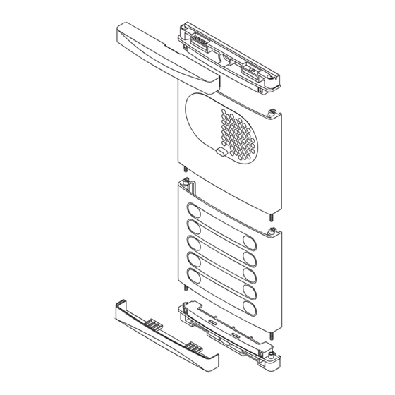
DOOR PANELS DESCRIPTION DOOR PANEL INSTALLATION nternal door panel mbedding box positioning. description. closing heads CE-6xx embedding boxes 2xxx grille module EL550 sound module 1850 3xxx 1650 push buttons module 1450 The upper part of the door panel should be placed at 1,65m. height roughly. The hole dimensions will depend on the number of door panel modules. - Page 4 DOOR PANEL INSTALLATION DOOR PANEL INSTALLATION lace the embedding ssembly the sound module. box. Insert the sound module in the grille module. Pass the wiring through the hole made in the bottom part For a proper assembly, align the light of the embedding box.
- Page 5 DOOR PANEL INSTALLATION DOOR PANEL INSTALLATION ssembly and wiring of the EL505 microprocessed ush buttons wiring. circuits in the general entrance door panel(s). For a quality finish, pass the push buttons wires through the spacer hole of the closest module. These circuits are to be assembled on the top of the embedding box.
-
Page 6: Lock Release Installation
DOOR PANEL INSTALLATION DOOR PANEL INSTALLATION lace the nameplate labels. lose the door panel. Fix the door panel by using the supplied screws. Open the label holder. Finish the door panel assembly by pressing the closing heads. Place the label and close. -
Page 7: Telephone Installation
TELEPHONE INSTALLATION POWER SUPPLY INSTALLATION escription of the T-900 nstalling the TF-104 transformer. telephone. The transformer must be installed in a dry and Telephone handset. protected place. It's recommended to protect 3,5 x 25 Speaker grille. the transformer by using a thermo-magnetic DIN-7971 Microphone hole. -
Page 8: Installation Diagram
INSTALLATION DIAGRAM INSTALLATION DIAGRAM eneral entrance door panel and two internal Building B ind. 2a ind. 2b Building A TF-104 TF-104 EL-551 EL-551 ind. 1a ind. 1b L1 L2 L1 L2 ind. 1a ind. 1b Main Main ind. 2a ind. 2b ind. -
Page 9: Optional Connections
OPTIONAL CONNECTIONS SECTIONS CHART arallel telephones installation. ections chart. Distance The maximum number of telephones placed Terminal 100m. 300m. in the same apartment is three. For each telephone placed in parallel 0, ind, 5, , 10, , P, P1, CO 0,25mm² 0,50mm²... -
Page 10: Troubleshooting Hints
TROUBLESHOOTING HINTS O Nothing operates. w Check the output transformer voltage between SEC terminals: it should have 12 to 17Va.c. If not, disconnect the transformer from the installation and measure again. If it's correct now, it means there is a short circuit in the installation: disconnect the transformer from mains and check the installation.
Need help?
Do you have a question about the T505i Stadio Plus and is the answer not in the manual?
Questions and answers