
Subscribe to Our Youtube Channel
Related Manuals for ACTi CAM-5130


Summary of Contents for ACTi CAM-5130
-
Page 1: Quick Installation Guide
Day & Night IP Zoom Camera CAM-5130/CAM-5140/CAM-5150 Ver. 061030 Quick Installation Guide... -
Page 2: Getting Started
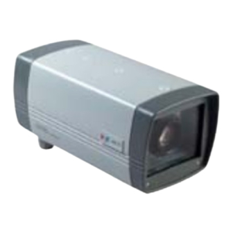
Getting Started PACKAGE CONTENTS CAM-5130 CAM-5140/CAM-5150 Indoor D&N IP Zoom Camera Outdoor D&N IP Zoom Camera Product CD Warranty Card Terminal Blocks Power Adaptor (Option) -
Page 3: Installation
Installation 1.2.1 How to set up Remove the rear cover 1.2.2 Physical description LAN Port & WAN Port NAME DESCRIPTION LRX+ LAN RX+ LRX- LAN RX- LTX- LAN TX- LTX+ LAN TX+ WTX- WAN TX-... - Page 4 WTX+ WAN TX+ WRX- WAN RX- WRX+ WAN RX+ DI/O & Video Output NAME DESCRIPTION Ground Pin Digital Output Ground Pin Digital Input Ground Pin Video_Out Analog Video Output LAN Link LED Indicator When the LAN Link LED light is on, the respective port is connected to the 10/100Mbps Ethernet network.
- Page 5 settings. Power Input DC 12V input. NAME DESCRIPTION DC12V Power Input (DC +12V) Ground Pin E-GND E-Ground Pin 1.2.3 Network cable pin define EIA/TIA-568 defines two kinds of piecing specifications, EIA/TIA-568A and EIA/TIA-568B. EIA/TIA-568A has already been eliminated, mostly use EIA/TIA-568B at present, arrange the order as white orange, orange, white green, blue, white blue, green, white brown, brown in its foot location, as drawn:...
- Page 6 The definition about Ethernet network card RJ-45 slot foot location is like the form: 10Base-T/100Base-TX Name Name LTX+ WTX+ LTX- WTX- LRX+ WRX+ Have not used Have not used LRX- WRX- Have not used Have not used...
- Page 7 1.2.4 Water-proof corrugated tubing Spec of “F1” is 10mm...
-
Page 8: Connect Necessary Cables
1.3 CONNECT NECESSARY CABLES The Ethernet cable and power cable are necessary for previewing function. Make sure all cables are correctly and firmly connected. 1. Connect an analog monitor to D&N IP Zoom Camera video out (BNC connector). 2. Connect the power adaptor to D&N IP Zoom Camera 3. -
Page 9: Quick Tour
Quick Tour This section guides you with a quick tour on D&N IP Zoom Camera. 2.1 Configure the D&N IP Zoom Camera 2.1.1 Make sure network environment Default IP of D&N IP Zoom Camera is 192.168.0.100. Please make sure the D&N IP Zoom Camera and your PC are on the same network segment before running the installation. - Page 10 2.1.2 Open Internet Explorer with IP address NOTE: If your web browser is earlier than IE6, then download IE6 is recommended. NOTE: The D&N IP Zoom Camera default IP address is set to 192.168.0.100 2.1.3 Login with default administrator’s account & password NOTE: Default administrator account is set to Admin, password is set to 123456, and click...
- Page 11 2.1.4 Preview the video NOTE: In your Client PC, please make sure the setting of Network Connections Type is set to Auto Negotation, since D&N IP Zoom Camera follows MII standard. Otherwise, you might not see the live image.
- Page 12 2.15 Set the new IP address *Host Name : Enter in the domain name, Default Host Name is ACTi. Language setting for Web Configurator after Save Reboot. Default setting is English. *Language : *IP Address : The IP address of the LAN interface. The default IP address is 192.168.0.100.
- Page 13 2.1.6 Check Default Video Setting NOTE: Please make sure the TV Input (NTSC / PAL) is meet your requirement, and click button. 2.1.7 Click Save Reboot to restore all settings and please wait about 30 seconds for system reboot.
Need help?
Do you have a question about the CAM-5130 and is the answer not in the manual?
Questions and answers