
Subscribe to Our Youtube Channel
Related Manuals for Supermicro x10qbi


Summary of Contents for Supermicro x10qbi
- Page 1 X10QBi Platform with X10QBi Baseboard AOM-X10QBi-A/L I/O Module X 1 0 Q B i - M E M 1 / M E M 2 Memory Card USER’S MANUAL Revision 1.1a...
- Page 2 This product, including software and docu- mentation, is the property of Supermicro and/or its licensors, and is supplied only under a license. Any use or reproduction of this product is not allowed, except as expressly permitted by the terms of said license.
- Page 3 *DDR4 ECC 1866 MHz (max) RDIMM/LRDIMM memory modules are supported when the X10QBi-MEM2 card is used in the system, and DDR3 ECC 1600 MHz (max) RDIMM/LRDIMM memory modules are supported when the X10QBi-MEM1 card is used in the system.
- Page 4 X10QBi Platform User’s Manual Conventions Used in this Manual Pay special attention to the following symbols for proper system motherboard instal- lation and to avoid damage done to the system or injury to yourself: Warning: Important information given to ensure proper system installation or to prevent...
-
Page 5: Contacting Supermicro
Super Micro Computer, Inc. 980 Rock Ave. San Jose, CA 95131 U.S.A. Tel: +1 (408) 503-8000 Fax: +1 (408) 503-8008 Email: marketing@supermicro.com (General Information) support@supermicro.com (Technical Support) Website: www.supermicro.com Europe Address: Super Micro Computer B.V. Het Sterrenbeeld 28, 5215 ML... -
Page 6: Table Of Contents
Memory Support for the X10QBi Platform ............ 2-16 Installing Memory Cards on the Baseboard ..........2-16 Memory Support for the X10QBi-MEM1 Rev. 1.01 Card ......2-17 Memory Support for the X10QBi-MEM1 Rev. 2.00 Card ......2-18 Memory Support for the X10QBi-MEM2 Rev. 1.01 Card ......2-19 I/O Module Connectors/Ports ................ - Page 7 Table of Contents NMI Button ....................2-25 Power LED ....................2-25 HDD LED ....................2-26 NIC1/NIC2 LED Indicators ............... 2-26 Overheat (OH)/Fan Fail/PWR Fail/UID LED ..........2-27 Power Fail LED ..................2-27 Reset Button ................... 2-28 Power Button ................... 2-28 Connecting Cables ..................
- Page 8 X10QBi Platform User’s Manual Battery Removal and Installation ..............3-5 Frequently Asked Questions ................3-6 Returning Merchandise for Service..............3-7 Chapter 4 BIOS Introduction ...................... 4-1 Main Setup ...................... 4-2 Advanced Setup Configurations..............4-4 Event Logs ....................4-28 IPMI .......................4-30 Security ......................4-32...
-
Page 9: Chapter 1 Overview
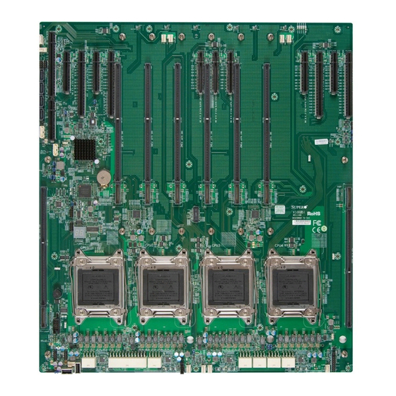
Checklist Congratulations on purchasing your computer system from an acknowledged leader in the industry. Supermicro's systems are designed with the utmost attention to detail to provide you with the highest standards in quality and performance. For more information regarding this product, please visit our website at www. - Page 10 X10QBi-F Platform User’s Manual X10QBi Baseboard Image X10QBi Baseboard Image (Rev. 1.01B) Note: All graphics shown in this manual were based upon the latest PCB revision available at the time of publishing this manual. The components installed in your system may or may not look exactly the same as the...
- Page 11 Chapter 1: Overview X10QBi Baseboard Layout X10QBi Baseboard Layout (Rev. 1.01B) JIPMB1 FAN10 LED10 LED9 LED8 LED7 LED14 I-SATA5 LED13 LED12 LED11 I-SATA3 JIO1 I-SATA4 I-SATA2 LEDIO1 JI2C1 JBT1 JI2C2 I-SATA0 JVRM_I2C1 JPME2 JPME1 LED15 LED28 LED23 JPT1 LED2 LED1...
- Page 12 AOM-X10QBi-A/L I/O Module Image AOM-X10QBi-A/L I/O Module Layout AOM-X10QBi-A/L Rev. 1.02 JPB1 JPG1 JPL1 LAN CTRL LED28 JEDUID1 AOM-X10QBi-A/L I/O Module Jumpers/Connectors/LED Indicator I/O Module Connectors I/O Module Jumpers/LED Indicator AOM-X10QBi-A/L I/O AOM-X10QBi-A/L I/O Jumpers Connectors Jump- Loca- Description Default...
- Page 13 Chapter 1: Overview Installing the AOM-X10QBi-A/L I/O Module on the Baseboard Note: Before you power on the system, be sure to install the AOM-X10QBi- A/L I/O module card on the SIO slot as shown in the figure below. Without the I/O module installed on the motherboard, your system will not boot.
-
Page 14: Memory Support
X10QBi-F Platform User’s Manual X10QBi-MEM1 Memory Card - Rev. 1.01 Rev. 1.01 X10QBi-MEM1 Memory Card Image *Always install DIMMs in the blue slots first in the order of DIMMA1, DIMMB1, DIMMC1, and DIMMD1 as marked above. X10QBi-MEM1 Rev. 1.01 Memory Card Layout... - Page 15 Chapter 1: Overview X10QBi-MEM1 Memory Card - Rev. 2.00 Rev. 2.00 X10QBi-MEM1 Memory Card Image *Always install DIMMs in the blue slots first in the order of DIMMA1, DIMMB1, DIMMC1, and DIMMD1 as marked above. X10QBi-MEM1 Rev. 2.00 Memory Card Layout...
- Page 16 X10QBi-F Platform User’s Manual X10QBi-MEM2 Memory Card - Rev. 1.01 Rev. 1.01 X10QBi-MEM2 Memory Card Image *Always install DIMMs in the blue slots first in the order of DIMMA1, DIMMB1, DIMMC1, and DIMMD1 as marked above. X10QBi-MEM2 Rev. 1.01 Memory Card Layout...
- Page 17 DIMM B2 DIMM D3 DIMM B3 DIMM C1 DIMM A1 DIMM C2 DIMM A2 DIMM A3 DIMM C3 Memory Buffer Controller Memory Buffer Controller BAR CODE X10QBi-MEM1 Rev. 1.01 X10QBi Rev:1.01B BAR CODE MAC CODE MAC CODE CPU1 CPU3 CPU2 CPU4...
- Page 18 X10QBi-F Platform User’s Manual X10QBi Baseboard Layout JIPMB1 FAN10 LED10 LED9 LED8 LED7 I-SATA5 LED14 LED13 LED12 LED11 I-SATA3 JIO1 I-SATA4 I-SATA2 LEDIO1 JI2C1 JBT1 JI2C2 I-SATA0 JVRM_I2C1 JPME2 JPME1 LED15 LED28 LED23 JPT1 LED2 LED1 X10QBi JLPC1 Rev:1.01B BAR CODE...
- Page 19 4-pin Fans 4-pin System/Cooling Fan Headers (FAN1-FAN10) Onboard Battery (See Chpt. 3 for Battery Disposal) COM1 (on the baseboard) Serial/COM Port Header 1 (on the X10QBi base- board) COM2 (on the I/O module) Serial/COM Part 2 (located on the AOM-X10QBi-A/L...
- Page 20 X10QBi-F Platform User’s Manual T-SGPIO 1/2 Serial_Link General Purpose I/O Headers USB0/1, USB2/3, USB6/7 Front Panel Accessible USB Connections USB4, USB5 Type A Front Panel USB Connectors 4/5 UID (on the I/O module) UID (Unit Identifier) Switch (SWUID1/SW1) VGA 1/2...
- Page 21 Chapter 1: Overview System Platform Features System The X10QBi system motherboard supports up to four Motherboard Intel® E7 series processors; each processor supports two full-width Intel QuickPath Interconnect (QPI) links (X10QBi) (with support of up to 9.6 GT/s Data Transfer Rate in each direction).
-
Page 22: Peripheral Devices
Four (4) PCI-E 3.0 x16 (Slot2/Slot4/Slot9/Slot11) • Seven (7) PCI E 3.0 x8 (Slot1/Slot3/Slot5/Slot6/ Slot7/ Slots (See Slot8/Slot10) Page 1-10) • I/O Module One (1) SIO Slot for AOM-X10QBi-A/L module Slot • Graphics AST2400 BMC Video Controller • Network One Intel Gigabit Ethernet Dual-Channel Controller for LAN 1/LAN 2 ports. - Page 23 (X10QBi system baseboard) Notes: 1. For IPMI configuration Instructions, please refer to the "Embedded IPMI Configuration User's Guide" available @ http://www.supermicro.com/sup- port/manuals/. 2. For PCI-E expansion slots to work properly, please refer to the instruc- tions listed on page 1-10.
-
Page 24: System Block Diagram
X10QBi-F Platform User’s Manual X10QBi System Block Diagram Power Power QPI 9.6 GT/s SMI2 Slot SMI2-CH0-3.2GT/s SMI2-CH0-3.2GT/s SMI2 Slot Connector Connector CPU3 CPU4 SMI2-CH1-3.2GT/s SMI2-CH1-3.2GT/s Power Power SMI2 Slot SMI2 Slot SMI2-CH2-3.2GT/s SMI2-CH2-3.2GT/s Connector Connector SMI2-CH3-3.2GT/s SMI2-CH3-3.2GT/s CPU4_S1-PCIE G3x8 in X8slot... -
Page 25: Processor/Pch Platform Overview
Processor/PCH Platform Overview Built upon the functionality and capability of the Intel E7 series processor(s) and the 602J PCH, the X10QBi system provides support for quad-processor-based HPC/Cluster/Database server platforms. With the Intel QuickPath interconnect (QPI) controller built in, the E7 series proces-... -
Page 26: Special Features
X10QBi-F Platform User’s Manual Special Features Recovery from AC Power Loss Basic I/O System (BIOS) provides a setting for you to determine how the system will respond when AC power is lost and then restored to the system. You can choose... -
Page 27: Acpi Features
This is even more important for processors that have high CPU clock rates. The X10QBi system motherboard includes a 24-pin ATX main system power con- nector (JWP1), six 8-pin power connectors (JWP2-JPW7), and a SATA DOM power connector (JWF1). Please connect these power connectors to the power supply to provide adequate power to the components and the system. -
Page 28: Advanced Power Management
X10QBi-F Platform User’s Manual management through an SMI or SCI function pin. It also features auto power management to reduce power consumption. Advanced Power Management The new advanced power management features supported by the motherboard includes the following: Intel Intelligent Power Node Manager (NM) (Available ®... -
Page 29: Chapter 2 Installation
The following statements are industry-standard warnings provided to alert the user of the situation when a bodily injury might occur. Should you have questions or experience difficulty, contact Supermicro's Technical Support department for assis- tance. Only certified technicians should attempt to install or configure components. - Page 30 X10QBi Platform User's Manual Attention Danger d'explosion si la pile n'est pas remplacée correctement. Ne la remplacer que par une pile de type semblable ou équivalent, recommandée par le fabricant. Jeter les piles usagées conformément aux instructions du fabricant. ¡Advertencia! Existe peligro de explosión si la batería se reemplaza de manera incorrecta.
-
Page 31: Product Disposal
Chapter 2: Installation Product Disposal Warning! Ultimate disposal of this product should be handled according to all national laws and regulations. 製品の廃棄 この製品を廃棄処分する場合、 国の関係する全ての法律 ・ 条例に従い処理する必要が あります。 警告 本产品的废弃处理应根据所有国家的法律和规章进行。 警告 本產品的廢棄處理應根據所有國家的法律和規章進行。 Warnung Die Entsorgung dieses Produkts sollte gemäß allen Bestimmungen und Gesetzen des Landes erfolgen. -
Page 32: Static-Sensitive Devices
X10QBi Platform User's Manual القىانين واللىائح الىطنية جميع وفقا ل ينبغي التعامل معه هذا المنتج من التخلص النهائي عند 경고! 이 제품은 해당 국가의 관련 법규 및 규정에 따라 폐기되어야 합니다. Waarschuwing De uiteindelijke verwijdering van dit product dient te geschieden in overeenstemming met alle nationale wetten en reglementen. -
Page 33: Processor And Heatsink Installation
CPU socket cap is in place and that none of the socket pins are bent; otherwise, contact your retailer immediately. Refer to the Supermicro website for updates on CPU support. Installing the E7-4800/8800 (V3) Processor(s) on the Main... - Page 34 X10QBi Platform User's Manual 1. Press the second load lever labeled 'Close 1st' to release the load plate that covers the CPU socket from its locking position. Pull lever away from Press down on Load the socket Lever 'Close 1st' 2.
- Page 35 Chapter 2: Installation 1. Use your thumb and the index finger to loosen the lever and open the load plate. 2. Using your thumb and index finger, hold the CPU on its edges. Align the CPU keys, which are semi-circle cutouts, against the socket keys. Socket Keys CPU Keys 3.
- Page 36 X10QBi Platform User's Manual 1. With the CPU inside the socket, inspect the four corners of the CPU to make sure that the CPU is properly installed. 2. Close the load plate with the CPU inside the socket. Lock the lever labeled 'Close 1st' first, then lock the lever labeled 'Open 1st' second.
-
Page 37: Installing A Passive Cpu Heatsink
Chapter 2: Installation Installing a Passive CPU Heatsink 1. Do not apply thermal grease to the heatsink or the CPU die; the required amount has already been applied. 2. Place the heatsink on top of the CPU so that the four mounting holes are aligned with those on the motherboard and the underlying heatsink bracket. -
Page 38: Removing The Heatsink
X10QBi Platform User's Manual Removing the Heatsink Warning: We do not recommend that the CPU or heatsink be removed. However, if you do need to uninstall the heatsink, please follow the instructions below to remove the heatsink to avoid damaging the CPU or CPU socket. -
Page 39: I/O Module And Memory Card Installation
Mainboard Note: After you've installed the CPUs and heatsinks on the baseboard, be sure to install the AOM-X10QBi-A/L I/O module card on the SIO slot as shown on the figure below before you power on the system. Without the I/O module being installed on the motherboard, your system cannot be turned on. - Page 40 X10QBi Platform User's Manual Installing DIMM Modules on the X10QBi Memory Card CAUTION Exercise extreme care when installing or removing DIMM modules to prevent any possible damage. Check Supermicro's website for recommended memory modules. 1. Install the desired number of DIMM modules on a memory card; each card supports up to 12 DIMMs.
- Page 41 2. Install one or two memory cards for each CPU installed on the baseboard, starting with SMI Slot P1M1. The X10QBi baseboard supports up to four pro- cessors. Refer to the table below to install memory cards that are populated with DIMM modules to the X10QBi baseboard.
- Page 42 X10QBi Platform User's Manual Removing the X10QBi Memory Card from the Baseboard Be sure to remove a memory card from the baseboard before you remove the RDIMM/LRDIMM modules from the memory card. To remove memory cards from the baseboard, follow the reverse sequence of memory card installation as shown on the memory population table on the previous page.
-
Page 43: Installing The System Motherboard Into The Chassis
I-SATA4 I-SATA2 LEDIO1 JI2C1 JBT1 JI2C2 I-SATA0 JVRM_I2C1 JPME2 JPME1 LED15 LED28 LED23 JPT1 LED2 LED1 X10QBi JLPC1 Rev:1.01B BAR CODE MAC CODE LED_PORT80 MAC CODE CPU1 CPU3 CPU2 CPU4 CLOSE 1st CLOSE 1st CLOSE 1st CLOSE 1st OPEN 1st... -
Page 44: Memory Support For The X10Qbi Platform
3. With eight MEM1 or MEM2 memory cards installed on the baseboard, the X10QBi supports up to 96 modules with a total size of 6TB supported. 4. When installing a DIMM module on a memory card, be sure to press the module straight down into the slot until it is properly seated and the PRES- ENT_LED is on. -
Page 45: Memory Support For The X10Qbi-Mem1 Rev. 1.01 Card
Mixing of DIMMs of different types or different speeds is not allowed. Note 2: For detailed information on memory support and updates, please refer to the SMC Recommended Memory List on our website at http://supermicro.com/ support/resources/mem.cfm. Note 3: Please refer to pages 1-6 to 1-9 in Chapter 1 for details on the MEM1 and MEM2 memory cards. -
Page 46: Memory Support For The X10Qbi-Mem1 Rev. 2.00 Card
Mixing of DIMMs of different types or different speeds is not allowed. Note 2: For detailed information on memory support and updates, please refer to the SMC Recommended Memory List on our website at http://supermicro.com/ support/resources/mem.cfm. Note 3: Please refer to pages 1-6 to 1-9 in Chapter 1 for details on the MEM1 and MEM2 memory cards. -
Page 47: Memory Support For The X10Qbi-Mem2 Rev. 1.01 Card
All products, dates, and figures are preliminary and are subject to change without any notice. Copyright © 2015, Intel Corporation. Note 2: For detailed information on memory support and updates, please refer to the SMC Recommended Memory List on our website at http://supermicro.com/ support/resources/mem.cfm. -
Page 48: I/O Module Connectors/Ports
I/O ports. Note: Before you power on the system, be sure to install the AOM-X10QBi- A/L I/O module card into the SIO slot as shown in the figure. Without the I/O module being installed on the baseboard, your system cannot be turned on. -
Page 49: Serial Ports (Com1: On The Baseboard, Com2: On The I/O Module)
Pin # Definition Pin # Definition A COM port header (COM1) is located on the X10QBi baseboard to provide front-accessible serial support. An- other COM port is located on the AOM- X10QBi-A/L I/O module for rear chassis Ground access. See the table on the right for pin definitions. -
Page 50: Ethernet Ports (On The I/O Module)
Ethernet Ports (On the I/O LAN Ports Module) Pin Definition Pin# Definition Two Ethernet ports (LAN1/LAN2) are TRCT2 IETCT located on the AOM-X10QBi-A/L I/O TRD2+ IET+ module. In addition, an IPMI_dedi- TRD2- IET- cated LAN is also located on the TRD3+... -
Page 51: Unit Identifier Switch/Leds (On The I/O Module)
Module) Pin# Definition A Unit Identifier (UID) switch on the AOM- Ground X10QBi-A/L I/O module, and two LED indica- Ground tors are located on the baseboard. The UID Button In switch is located next to the LAN ports on Ground the I/O module. -
Page 52: Front Control Panel
JF1 contains header pins for various buttons and indicators that are normally lo- cated on a control panel at the front of the chassis. These connectors are designed specifically for use with Supermicro's server chassis. See the figure below for descriptions of the various control-panel buttons and LED indicators. Refer to the following section for descriptions and pin definitions. -
Page 53: Front Control Panel Pin Definitions
FP PWRLED JPME2 JPME1 LED15 3.3V HDD LED LED28 LED23 JPT1 LED2 LED1 NIC1 Link LED NIC1 Active LED X10QBi JLPC1 Rev:1.01B BAR CODE MAC CODE LED_PORT80 MAC CODE NIC2 Active LED NIC2 Link LED CPU1 CPU3 CPU2 CPU4 Blue Led Cathode... -
Page 54: Hdd Led
X10QBi Platform User's Manual HDD LED HDD LED Pin Definitions (JF1) The HDD LED connection is located Pin# Definition on pins 13 and 14 of JF1. Attach a 3.3V Standby cable here to indicate HDD activity. HD Active Refer to the table on the right for pin definitions. -
Page 55: Overheat (Oh)/Fan Fail/Pwr Fail/Uid Led
FP PWRLED JPME2 JPME1 LED15 HDD LED 3.3V LED28 LED23 JPT1 LED2 NIC1 Link LED NIC1 Active LED LED1 X10QBi JLPC1 Rev:1.01B BAR CODE MAC CODE LED_PORT80 MAC CODE NIC2 Active LED NIC2 Link LED CPU1 CPU3 CPU2 CPU4 Blue Led Cathode... -
Page 56: Reset Button
X10QBi Platform User's Manual Reset Button Reset Button Pin Definitions (JF1) The Reset Button connection is located Pin# Definition on pins 3 and 4 of JF1. Attach it to a Reset hardware reset switch on the computer Ground case. Refer to the table on the right for pin definitions. -
Page 57: Connecting Cables
F. JPW6: 8-pin PWR (Req'd) JPME2 G. JPW7: 8-pin PWR (Req'd) JPME1 LED15 LED28 H. JSD1: SATA Device PWR (Req'd for LED23 JPT1 LED2 LED1 X10QBi JLPC1 SATA devices) Rev:1.01B BAR CODE MAC CODE LED_PORT80 MAC CODE CPU1 CPU3 CPU2... -
Page 58: Fan Headers
X10QBi Platform User's Manual Fan Headers Fan Header Pin Definitions The X10QBi system board has ten sys- Pin# Definition tem fan headers and ten CPU_card fan Ground headers. All these are 4-pin fans and are +12V backward_compatible with the traditional Tachometer 3-pin fan. -
Page 59: Internal Buzzer
I-SATA4 I-SATA2 LEDIO1 JI2C1 JBT1 JI2C2 I-SATA0 JVRM_I2C1 JPME2 JPME1 LED15 LED28 LED23 JPT1 LED2 LED1 X10QBi JLPC1 Rev:1.01B BAR CODE MAC CODE LED_PORT80 MAC CODE CPU1 CPU3 CPU2 CPU4 CLOSE 1st CLOSE 1st CLOSE 1st CLOSE 1st OPEN 1st... -
Page 60: Overheat Led/Fan Fail
X10QBi Platform User's Manual Overheat LED/Fan Fail Overheat LED Pin Definitions The JOH1 header is used to connect Pin# Definition an LED indicator to provide warnings 5vDC of chassis overheating or fan failure. OH Active This LED will blink when a fan failure occurs. -
Page 61: Power Smb
I-SATA4 I-SATA2 LEDIO1 JI2C1 JBT1 JI2C2 I-SATA0 JVRM_I2C1 JPME2 JPME1 LED15 LED28 LED23 JPT1 LED2 LED1 X10QBi JLPC1 Rev:1.01B BAR CODE MAC CODE LED_PORT80 MAC CODE CPU1 CPU3 CPU2 CPU4 CLOSE 1st CLOSE 1st CLOSE 1st CLOSE 1st OPEN 1st... -
Page 62: Universal Serial Bus (Usb) (On The Main Board)
X10QBi Platform User's Manual Universal Serial Bus (USB) (On USB (0/1, 2/3) Type A USB Pin Definitions the Main Board) (USB4, USB5) Pin Definitions USB 0/2/6 USB 1/3/7 Two Universal Serial Bus headers pro- Pin # Definition Pin # Definition... -
Page 63: Jumper Settings
Module) Jumper Settings Jumper Setting Definition JPL1 enables or disables the LAN Enabled (default) Port1/LAN Port2 on the X10QBi-A I/O Disabled module. Refer to the table on the right for jumper settings. The default setting is Enabled. A. LAN Enable AOM-X10QBi-A/L Rev. -
Page 64: Bmc Enable (On The I/O Module)
BMC Enable (On the I/O Module) BMC Enable Jumper Settings Jumper JPB1 allows you to enable the Jumper Setting Definition BMC controller on the X10QBi-A I/O Pins 1-2 BMC Enable (Default) module for IPMI/KVM support. Refer to Pins 2-3 Disabled the table on the right for jumper settings. -
Page 65: Cmos Clear
I-SATA4 I-SATA2 LEDIO1 JI2C1 JBT1 JI2C2 I-SATA0 JVRM_I2C1 JPME2 JPME1 LED15 LED28 LED23 JPT1 LED2 LED1 X10QBi JLPC1 Rev:1.01B BAR CODE MAC CODE LED_PORT80 MAC CODE CPU1 CPU3 CPU2 CPU4 CLOSE 1st CLOSE 1st CLOSE 1st CLOSE 1st OPEN 1st... -
Page 66: I 2 C Bus To Pci-Exp. Slots
X10QBi Platform User's Manual C Bus to PCI-Exp. Slots C for PCI-E slots Jumper Settings Use Jumpers JI C1 and JI C2 to connect the Jumper Setting Definition System Management Bus (I C) to the PCI-E Closed Enabled slots to improve system performance. These... -
Page 67: Management Engine (Me) Recovery
I-SATA4 I-SATA2 LEDIO1 JI2C1 JBT1 JI2C2 I-SATA0 JVRM_I2C1 JPME2 JPME1 LED15 LED28 LED23 JPT1 LED2 LED1 X10QBi JLPC1 Rev:1.01B BAR CODE MAC CODE LED_PORT80 MAC CODE CPU1 CPU3 CPU2 CPU4 CLOSE 1st CLOSE 1st CLOSE 1st CLOSE 1st OPEN 1st... -
Page 68: 2-10 Onboard Led Indicators
X10QBi Platform User's Manual 2-10 Onboard LED Indicators Link LED Activity LED LAN LEDs (On the I/O Module) Two LAN ports (LAN 1/LAN 2) are located LAN 1/LAN 2 Link LED (Left) LED State on the I/O module of the system. Each Eth-... -
Page 69: 2-11 Serial Ata Connections
Pin Definitions Serial ATA Ports Pin# Definition Six Serial ATA Ports (I-SATA0-I-SATA5) Ground are located on the X10QBi baseboard. TX_P I-SATA0/1 support SATA 3.0; I-SATA2-5 TX_N support SATA 2.0. These ports, support- Ground ed by the Intel PCH, provide serial-link... - Page 70 X10QBi Platform User's Manual Notes 2-42...
-
Page 71: Troubleshooting Procedures
USB connections. 3. Remove all I/O module, and add-on cards. 4. Install the AOM-X10QBi-A/L I/O module first (-making sure it is fully seated) and connect the front panel connectors to the system board. -
Page 72: System Boot Failure
X10QBi Platform User's Manual No Video 1. If the power is on, but you have no video, remove the I/O module, all the add- on cards and cables. 2. Use the speaker to determine if any beep codes exist. Refer to Appendix A for details on beep codes. -
Page 73: Memory Errors
RAM speed of DIMMs are used in the system. 3. Make sure that you are using the correct type of memory modules as recom- mended by Supermicro. Please refer to the memory support section on Page 2-16 to Page 2-19. -
Page 74: Technical Support Procedures
Technical Support Procedures Before contacting Technical Support, please take the following steps. Also, please note that as a system and motherboard manufacturer, Supermicro also sells prod- ucts through its channels, so it is best to first check with your distributor or reseller for troubleshooting services. -
Page 75: Battery Removal And Installation
1. Please go through the "Troubleshooting Procedures" and "Frequently Asked Question" (FAQ) sections in this chapter or see the FAQs on our website (http:// www.supermicro.com/) before contacting Technical Support. 2. BIOS upgrades can be downloaded from our website (http://www.supermicro. com). -
Page 76: Frequently Asked Questions
Note : The SPI BIOS chip used in this system board cannot be removed. Send your system board back to our RMA Department at Supermicro for repair. For BIOS Recovery instructions, please refer to the AMI BIOS Recovery Instructions posted at http://www.supermicro.com. -
Page 77: Returning Merchandise For Service
Shipping and handling charges will be applied for all orders that must be mailed when service is complete. For faster service, you can also request an RMA autho- rization online (http://www.supermicro.com). This warranty only covers normal consumer use and does not cover any damage incurred in shipping or from any failure caused by alternation, misuse, abuse, or improper maintenance of products. - Page 78 X10QBi Platform User's Manual Notes...
-
Page 79: Chapter 4 Bios
BIOS Introduction This chapter describes the AMI BIOS setup utility for the X10QBi Platform. It also provides the instructions on how to navigate the AMI BIOS setup utility screens. The AMI ROM BIOS is stored in a Flash EEPROM and can be easily updated. -
Page 80: Main Setup
<Delete> at the appropriate time during system boot. Note: For AMI UEFI BIOS Recovery, please refer to the UEFI BIOS Recov- ery User Guide posted @ http://www.supermicro.com/support/manuals/. Starting the Setup Utility Normally, the only visible Power-On Self-Test (POST) routine is the memory test. - Page 81 The date must be entered in Day MM/DD/YYYY format. The time is entered in HH:MM:SS format. (Note: The time is in the 24-hour format. For example, 5:30 P.M. appears as 17:30:00.). Supermicro X10QBi Version This item displays the SMC version of the BIOS ROM used in this system.
-
Page 82: Advanced Setup Configurations
X10QBi Platform User’s Manual Advanced Setup Configurations Select the Advanced tab to access the following submenu items. Boot Features Boot Configuration Quiet Boot Use this item to select bootup screen display between POST messages and the OEM logo. Select Disabled to display the POST messages. Select Enabled to display the OEM logo instead of the normal POST messages. -
Page 83: Power Configuration
Chapter 4: AMI BIOS Re-try Boot If this item is set to Enabled, the system BIOS will continuously try to boot from the selected boot drive. The options are Disabled, Legacy Boot, and EFI Boot. Power Configuration Watch Dog Function If enabled, the Watch Dog timer will allow the system to automatically reboot when a non-recoverable error that lasts for more than five minutes occurs. - Page 84 X10QBi Platform User’s Manual • L2 Cache RAM • L3 Cache RAM • Processor 0 Version • Processor 1 Version • Processor 2 Version • Processor 3 Version Clock Spread Spectrum Select Enable to allow the BIOS to attempt to reduce the level of Electromagnetic Interference caused by the components whenever needed.
- Page 85 Chapter 4: AMI BIOS Intel Virtualization Technology (Available when supported by the CPU) ® Select Enable to support Intel Virtualization Technology, which will allow one platform to run multiple operating systems and applications in independent parti- tions, creating multiple "virtual" systems in one physical computer. The options are Disable and Enable.
-
Page 86: Advanced Power Management Configuration
X10QBi Platform User’s Manual Direct Cache Access (DCA) Select Enable to use Intel DCA (Direct Cache Access) Technology to improve the efficiency of data transferring and accessing. The options are Disable and Enable. AES-NI Select Enable to use the Intel Advanced Encryption Standard (AES) New Instruc- tions (NI) to ensure data security. - Page 87 Chapter 4: AMI BIOS CPU C State Control (Available when Power Technology is set to Custom) C2C3TT (C2-to-C3 Transaction Timer) This item is used to set the transaction timer from the C2 state to the C3 state. Enter 0 for Auto, which will allow the BIOS to configure the transaction timer automatically.
-
Page 88: Chipset Configuration
X10QBi Platform User’s Manual Energy/Performance BIAS Setting Use this item to select an appropriate fan setting to achieve maximum system performance (with maximum cooling) or maximum energy efficiency with maxi- mum power saving). The fan speeds are controlled by the firmware management via IPMI 2.0. - Page 89 Chapter 4: AMI BIOS Link Speed Use this item to select the PCI-E link speed for the PCI-E port specified by the user. The options for CPU-PCH DMI port are Auto, GEN1 (2.5 GT/s), and GEN2 (5 GT/s). The options for Onboard LAN are Auto, GEN1 (2.5 GT/s), GEN2 (5 GT/s), and GEN3 (8 GT/s).
- Page 90 X10QBi Platform User’s Manual Link Speed Use this item to select the PCI-E link speed for the PCI-E port specified by the user. The options are Auto, GEN1 (2.5 GT/s), GEN2 (5 GT/s), and GEN3 (8 GT/s). IIO3 Configuration CPU4 Slot8 x8/CPU4 Slot10 x8/CPU4 Slot11 x16 Use the items below to configure the PCI-E settings for a PCI-E port specified by the user.
- Page 91 Chapter 4: AMI BIOS Intel VT for Directed I/O (VT-d) Intel VT for Directed I/O (VT-d) ® Select Enable to enable Intel Virtualization Technology support for Direct I/O VT-d by reporting the I/O device assignments to the VMM (Virtual Machine Monitor) through the DMAR ACPI Tables.
-
Page 92: Memory Configuration
X10QBi Platform User’s Manual Link L0p Enable Select Enable for Link L0p support. The options are Disable and Enable. Link L1 Enable Select Enable for Link L1 support. The options are Disable and Enable. Legacy VGA Socket Enter the VGA socket number (from 0-7) that will be used to support legacy VGA. - Page 93 Chapter 4: AMI BIOS ODT Timing Mode Use this feature to set the ODT (On-Die Termination) Timing mode for the memory controller to enhance memory performance. The options are Aggres- sive Timing and Conservative Timing. MxB Rank Sharing Mapping Use this feature to select the address-mapping setting for memory-rank sharing to enhance extended multimedia platform performance.
- Page 94 X10QBi Platform User’s Manual • Memory Channel • DIMM Frequency Memory RAS (Reliability Availability Serviceability) Configuration This submenu will display the following items: • Current Memory Mode • Mirroring • Sparing Memory Rank Sparing This item indicates if memory rank sparing is supported by the motherboard.
-
Page 95: South Bridge
Chapter 4: AMI BIOS Rank Interleaving Use this feature to select a rank memory interleaving method. Auto, 1-way Inter- leave, 2-way Interleave, 4-way Interleave, and 8-way Interleave. Demand Scrub Demand Scrubbing is a process that allows the CPU to correct correctable memory errors found on a memory module. -
Page 96: Sata Configuration
X10QBi Platform User’s Manual Legacy USB Support (Available when USB Functions is not Disabled) Select Enabled to support legacy USB devices. Select Auto to disable legacy sup- port if USB devices are not present. Select Disabled to have USB devices available for EFI (Extensive Firmware Interface) applications only. - Page 97 Chapter 4: AMI BIOS Hot Plug (Available when "Configure SATA as" is set to RAID or AHCI) Select Enabled to support Hot-plugging for the selected SATA port which will al- low the user to replace a device without shutting down the system. The options are Disabled and Enabled.
- Page 98 X10QBi Platform User’s Manual Maximum Read Request Select Auto to allow the system BIOS to automatically set the maximum Read Request size for a PCI-E device to enhance system performance. The options are Auto, 128 Bytes, 256 Bytes, 512 Bytes, 1024 Bytes, 2048 Bytes, and 4096 Bytes.
-
Page 99: Acpi Settings
Chapter 4: AMI BIOS Onboard LAN OpROM (Option ROM) Type Select Legacy to boot the computer using a legacy network device. Select EFI to boot the computer using an EFI network device. The options are Legacy and EFI. Load Onboard LAN1 Option ROM/Load Onboard LAN2 Option ROM Select Enabled to enable the onboard LAN1/LAN2 Option ROM which will allow the user to boot the computer using a network device. - Page 100 X10QBi Platform User’s Manual Note: The computer will reboot in order to execute the pending commands and change the state of the security device. Current Status Information: This item displays the information regarding the current TPM status. TPM Enable Status This item displays the status of TPM Support to indicate if TPM is currently enabled or disabled.
-
Page 101: Super Io Configuration
Chapter 4: AMI BIOS Super IO Configuration Super IO Chip: This item displays the Super IO chip used in the motherboard. Serial Port 1 Configuration Serial Port Select Enabled to enable a serial port specified by the user. The options are En- abled and Disabled. -
Page 102: Serial Port Console Redirection
X10QBi Platform User’s Manual Serial Port Console Redirection COM 1 Console Redirection This submenu allows the user to configure the following Console Redirection set- tings for this port. Console Redirection Select Enabled for Console Redirection support. The options are Enabled and Disabled. - Page 103 Chapter 4: AMI BIOS Parity A parity bit can be sent along with regular data bits to detect data transmission errors. Select Even if the parity bit is set to 0, and the number of 1's in data bits is even. Select Odd if the parity bit is set to 0, and the number of 1's in data bits is odd.
- Page 104 X10QBi Platform User’s Manual Redirection After BIOS Post Use this feature to enable or disable legacy console redirection after BIOS POST (Power-On Self-Test). When this item is set to Bootloader, legacy console redirection is disabled before booting the OS. When this item is set to Always Enable, legacy console redirection remains enabled when booting the OS.
-
Page 105: Iscsi Configuration
Chapter 4: AMI BIOS ing data when the receiving buffer is empty. The options are None, Hardware RTS/CTS, and Software Xon/Xoff. The setting for each these features is displayed: Data Bits, Parity, Stop Bits iSCSI Configuration This item displays iSCSI configuration information: iSCSI Initiator Name This item displays the name of the iSCSI Initiator, which is an unique name used in the world. -
Page 106: Event Logs
X10QBi Platform User’s Manual Event Logs Use this feature to configure Event Log settings. Change SMBIOS Event Log Settings This feature allows the user to configure SMBIOS Event settings. Enabling/Disabling Options SMBIOS Event Log Select Enabled to enable SMBIOS (System Management BIOS) Event Logging during system boot. -
Page 107: View Smbios Event Log
Chapter 4: AMI BIOS SMBIOS Event Log Standard Settings Log System Boot Event Select Enabled to log system boot events. The options are Disabled and Enabled. MECI (Multiple Event Count Increment) Enter the increment value for the multiple event counter. Enter a number between 1 to 255. -
Page 108: Ipmi
X10QBi Platform User’s Manual IPMI Select the IPMI (Intelligent Platform Management Interface) tab to access the fol- lowing submenu items. These items indicates your system IPMI firmware revision number and status. • IPMI Firmware Revision • IPMI Status System Event Log ... -
Page 109: Bmc Network Configuration
Chapter 4: AMI BIOS When SEL is Full This feature allows the user to determine what the AMI BIOS should do when the system event log is full. Select Erase Immediately to erase all events in the log when the system event log is full. The options are Do Nothing and Erase Immediately. Note: After making changes on a setting, be sure to reboot the system for the changes to take effect. -
Page 110: Security
X10QBi Platform User’s Manual Security This menu allows the user to configure the following security settings for the system. Administrator Password Use this item to set the administrator password which is required to enter the BIOS setup utility. The length of the password should be from 3 characters to 20 characters long. -
Page 111: Boot
Chapter 4: AMI BIOS Boot This submenu allows the user to configure the following boot settings for the system. Boot Mood Select Use this item to configure boot mood select settings for the machine. The options are Legacy, UEFI, and Dual. Fixed Boot Order Priorities This option prioritizes the order of bootable devices that the system to boot from. - Page 112 X10QBi Platform User’s Manual Hard Disk Drive BBS Priorities This item sets the boot sequence of available hard disk drives. • Boot Option #1 Network Drive BBS Priorities • Boot Option #1 UEFI Application Boot Priorities •...
-
Page 113: Save & Exit
Chapter 4: AMI BIOS Save & Exit This submenu allows the user to configure the Save and Exit settings for the system. Save Changes and Exit When completing the system configuration changes, select this option to save the changes and exit from the BIOS setup utility. When a dialog box appears, asking you if you want to save configuration and exit, select Yes to save the changes and exit from the BIOS setup utility. - Page 114 X10QBi Platform User’s Manual to save configuration, select Yes to save the changes, or select No to return to the BIOS without making changes. Discard Changes Select this feature and press <Enter> to discard all the changes and return to the BIOS setup.
-
Page 115: Appendix A Bios Post Error Beep Codes
Appendix A: BIOS POST Error Codes Appendix A BIOS POST Error Beep Codes During the POST (Power-On Self-Test) routines, which are performed each time the system is powered on, errors may occur. Non-fatal errors are those which, in most cases, allow the system to continue the bootup process. - Page 116 X10QBi Platform User's Manual Notes...
-
Page 117: Appendix B Software Installation Instructions
To install these programs, click the icons to the right of these items. Note: To install the Windows OS, please refer to the instructions posted on our website at http://www.supermicro.com/support/manuals/. Driver/Tool Installation Display Screen Note 1. Click the icons showing a hand writing on the paper to view the readme files for each item. -
Page 118: Configuring Superdoctor Iii
X10QBi Platform User's Manual B-2 Configuring SuperDoctor III The SuperDoctor® III program is a Web-based management tool that supports re- mote management capability. It includes Remote and Local Management tools. The local management is called the SD III Client. The SuperDoctor III program included on the CD_ROM that came with your system motherboard allows you to monitor the environment and operations of your system. - Page 119 Appendix B: Software Installation Instructions SuperDoctor III Interface Display Screen-II (Remote Control) Note: SD III software and the user's manual can be downloaded from our website at: http://www.supermicro.com/products/accessories/soft- ware/SuperDoctorIII.cfm. For Linux, we will recommend that you use SuperDoctor II.
- Page 120 X10QBi Platform User's Manual Notes...
-
Page 121: Appendix C Uefi Bios Recovery Instructions
Flashing the wrong BIOS can cause irreparable damage to the system. In no event shall Supermicro be liable for direct, indirect, special, incidental, or consequential damages arising from a BIOS update. If you need to update the BIOS, do not shut down or reset the system while the BIOS is updating to avoid possible boot failure. - Page 122 Root "\" Directory of a USB device or a writeable CD/DVD. Note: If you cannot locate the "Super.ROM" file in your driver disk, visit our website at www.supermicro.com to download the BIOS image into a USB flash device and rename it "Super.ROM" for BIOS recovery use.
- Page 123 Appendix C: UEFI BIOS Recovery 3. While powering on the system, please keep pressing <Ctrl> and <Home> si- multaneously on your keyboard until the following screen (or a screen similar to the one below) displays. 4. After locating the new BIOS binary image, the system will enter the BIOS Recovery menu as shown below.
- Page 124 X10QBi Motherboard User’s Manual 5. When the screen as shown above displays, using the arrow key, select the item "Proceed with flash update" and press the <Enter> key. You will see the progress of BIOS recovery as shown in the screen below.
-
Page 125: Appendix D Dual Boot Block
Appendix D: Dual Boot Block Appendix D Dual Boot Block D-1 Introduction This motherboard supports the Dual Boot Block feature, which is the last-ditch mechanism to recover the BIOS boot block. This section provides an introduction to the feature. BIOS Boot Block A BIOS boot block is the minimum BIOS loader required to enable necessary hardware components for the BIOS crisis recovery flash used to update the main BIOS block. -
Page 126: D-2 Steps To Reboot The System By Using Jumper Jbr1
X10QBi Platform User's Manual D-2 Steps to Reboot the System by Using Jumper JBR1 1. Power down the system. 2. Close pins 2-3 on Jumper JBR1, and power on the system. 3. Follow the BIOS recovery SOP listed in the previous chapter (Appendix C). - Page 127 (Disclaimer Continued) The products sold by Supermicro are not intended for and will not be used in life support systems, medical equipment, nuclear facilities or systems, aircraft, aircraft devices, aircraft/emergency communication devices or other critical systems whose failure to perform be reasonably expected to result in significant injury or loss of life or catastrophic property damage.
Need help?
Do you have a question about the x10qbi and is the answer not in the manual?
Questions and answers