Table of Contents
Advertisement
Quick Links
Advertisement
Table of Contents

Related Manuals for Supermicro X10QBL-CT


Summary of Contents for Supermicro X10QBL-CT
- Page 1 X10QBL-CT X10QBL USER’S MANUAL Revision 1.0...
- Page 2 This product, including software and docu- mentation, is the property of Supermicro and/or its licensors, and is supplied only under a license. Any use or reproduction of this product is not allowed, except as expressly permitted by the terms of said license.
-
Page 3: About This Motherboard
MCTP Protocol, and Intel® Node Manager 3.0. This motherboard is opti- mized for high-performance, cost-effective, cloud-computing systems. Please refer to our website (http://www.supermicro.com) for CPU and memory support updates. Manual Organization Chapter 1 describes the features, specifications and performance of the mother- board. -
Page 4: Conventions Used In The Manual
X10QBL-CT/X10QBL Motherboard User’s Manual Conventions Used in the Manual Pay special attention to the following symbols for proper system installation: Warning: Important information given to ensure proper system installation or to prevent damage to the components or injury to yourself;... -
Page 5: Contacting Supermicro
Super Micro Computer, Inc. 980 Rock Ave. San Jose, CA 95131 U.S.A. Tel: +1 (408) 503-8000 Fax: +1 (408) 503-8008 Email: marketing@supermicro.com (General Information) support@supermicro.com (Technical Support) Web Site: www.supermicro.com Europe Address: Super Micro Computer B.V. Het Sterrenbeeld 28, 5215 ML... -
Page 6: Table Of Contents
System Health Monitoring ................1-12 ACPI Features ....................1-13 Power Supply ....................1-13 Advanced Power Management ..............1-13 Intel Intelligent Power Node Manager (NM) (Available when the Supermicro ® Power Manager [SPM] is Installed) .............. 1-13 Management Engine (ME) ................1-14 Chapter 2 Installation Standardized Warning Statements .............. - Page 7 LAN LEDs ....................2-36 IPMI Dedicated LAN LEDs ............... 2-36 Onboard Power LED ................2-37 BMC Heartbeat LED ................2-37 SAS Heartbeat LED (for X10QBL-CT only) ..........2-38 SAS Activity LED (for X10QBL-CT only) ..........2-38 2-11 SATA/SAS 3.0 Connections ................2-39 SATA 3.0 Ports ..................
- Page 8 X10QBL-CT/X10QBL Motherboard User’s Manual Chapter 3 Troubleshooting Troubleshooting Procedures ................3-1 Technical Support Procedures ................ 3-4 Battery Removal and Installation ..............3-6 Battery Removal ....................3-6 Proper Battery Disposal .................. 3-6 Frequently Asked Questions ................3-7 Returning Merchandise for Service..............3-8 Chapter 4 BIOS Introduction ......................
-
Page 9: Chapter 1 Overview
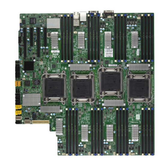
Checklist Congratulations on purchasing your computer motherboard from an acknowledged leader in the industry. Supermicro boards are designed with the utmost attention to detail to provide you with the highest standards in quality and performance. Note 1: The X10QBL(-CT) motherboard was designed to be used with a Supermicro-proprietary chassis as an integrated server platform. - Page 10 X10QBL-CT/X10QBL Motherboard User’s Manual X10QBL(-CT) Motherboard Image Note: All graphics shown in this manual were based upon the latest PCB revision available at the time of publishing of the manual. The motherboard you've received may or may not look exactly the same as the graphics...
- Page 11 JPWR4 JPS4 JPS1 JPWR3 USB8 JPI2C1 JPWR2 JPWR1 LED15 LEDPWR FAN7 FAN1 Differences between the X10QBL-CT and the X10QBL Item/Description X10QBL-CT X10QBL SAS Support LSI SAS Controller 3008 SAS0-3 (JSAS1) Supported SAS4-7 (JSAS2) Supported LAN Connection Speed 10G (TGLAN) supported...
- Page 12 X10QBL-CT/X10QBL Motherboard User’s Manual X10QBL(-CT) Quick Reference USB0/1 USB2 COM1 LED1 LEDBMC FAN9 IPMI_LAN LAN CTRL LAN1/2 FAN10 JPTG1 MAC CODE IPMI CODE BAR CODE SAS CODE JBT1 USB4/5 X10QBL-CT USB6/7 IB CODE BIOS Rev. 1.01 CPU4 CPU2 CLOSE 1st...
- Page 13 JIPMB1 4-pin external BMC I C header (for IPMI-card support) Chassis intrusion header Power System Management Bus (SMB) header JPSAS1 (for X10QBL-CT) 2-pin power connector for SAS HDD status support JPWR1 24-pin power connection header JPWR2/3/4/5 8-pin power connectors LAN1/2 (for X10QBL)
- Page 14 X10QBL-CT/X10QBL Motherboard User’s Manual JSTBY1 Standby power connection header JTPM1 TPM (Trusted Platform Module)/Port 80 header (CPU1) Slot1 PCI-Exp. 3.0x16 slot (supported by CPU1) (CPU2) Slot2/4 PCI-Exp. 3.0x8 slots (supported by CPU2) (CPU2) Slot3 PCI-Exp. 3.0x16 slot (supported by CPU2)
-
Page 15: Motherboard Features
Intel i350 Gigabit (10/100/1000 Mb/s) Ethernet con- troller for LAN Port 1/Port 2 (X10QBL only), • Intel X540 10-Gigabit Ethernet controller for 10G- LAN (TLAN) Port1/Port 2 (X10QBL-CT only) • ASpeed 2400 Baseboard Controller (BMC) supports IPMI_LAN 2.0 I/O Devices SATA Connections •... -
Page 16: Peripheral Devices
Management Main switch override mechanism • Power-on mode for AC power recovery • Intel Intelligent Power Node Manager 3.0 (Avail- ® able when the Supermicro Power Manager [SPM] is installed and special power supply is used.) • Management Engine (ME) - Page 17 SuperDoctor 5, Watch Dog, NMI • Chassis Intrusion header and detection • Dimensions 16.40" (L) x 16.79" (W) (426.47 mm x 424.18 mm) Note: For IPMI Configuration instructions, please refer to the Embedded IPMI Configuration User's Guide available @ http://www.supermicro.com/ support/manuals/.
-
Page 18: System Block Diagram
X10QBL-CT/X10QBL Motherboard User’s Manual Memory Memory PCIE PCIE Buffer Buffer VMSE0 VMSE0 CTRL CTRL CPU2 CPU3 QPI0 QPI0 Memory Memory Buffer Buffer VMSE1 VMSE1 CTRL CTRL QPI2 QPI1 QPI1 QPI2 Memory Memory QPI0 QPI1 QPI1 QPI0 Buffer Buffer VMSE0 VMSE0... -
Page 19: Processor And Chipset Overview
Chapter 1: Overview Processor and Chipset Overview Built upon the functionality and capability of the Intel E7-4800 v2 processors (Socket R1) and the Intel C602J PCH, the X10QBL(-CT) motherboard provides the best solution for cost-effective, high-performance, cloud-computing platforms. With support of the new Intel Microarchitecture 22nm Processing technology, the X10QBL(-CT) dramatically increases performance for a multitude of server applications. -
Page 20: Special Features
X10QBL-CT/X10QBL Motherboard User’s Manual Special Features Recovery from AC Power Loss The Basic I/O System (BIOS) provides a setting that determines how the system will respond when AC power is lost and then restored to the system. You can choose for the system to remain powered off (in which case you must press the power switch to turn it back on), or for it to automatically return to the power-on state. -
Page 21: Acpi Features
Also, be sure to use the power supply recommended for this motherboard by Supermicro. It is recommended that you also install a power surge protector to help avoid prob- lems caused by power surges. -
Page 22: Management Engine (Me)
X10QBL-CT/X10QBL Motherboard User’s Manual Note: Support for IPNM Specification Version 1.5 or Vision 2.0 depends on the power supply used in the system. Management Engine (ME) Management Engine, an ARC controller embedded in the PCH, provides Server Platform Services (SPS) support to your system. The services provided by SPS are different from those provided by the ME on the client platforms. -
Page 23: Chapter 2 Installation
The following statements are industry-standard warnings, provided to warn the user of situations which may cause bodily injury. Should you have questions or experi- ence difficulty, contact Supermicro Technical Support for assistance. Only certified technicians should attempt to install or configure components. - Page 24 X10QBL-CT/X10QBL Motherboard User’s Manual Attention Danger d'explosion si la pile n'est pas remplacée correctement. Ne la remplacer que par une pile de type semblable ou équivalent, recommandée par le fabricant. Jeter les piles usagées conformément aux instructions du fabricant. ¡Advertencia! Existe peligro de explosión si la batería se reemplaza de manera incorrecta.
-
Page 25: Product Disposal
Chapter 2: Installation Product Disposal Warning! Ultimate disposal of this product should be handled according to all national laws and regulations. 製品の廃棄 この製品を廃棄処分する場合、 国の関係する全ての法律 ・ 条例に従い処理する必要が あります。 警告 本产品的废弃处理应根据所有国家的法律和规章进行。 警告 本產品的廢棄處理應根據所有國家的法律和規章進行。 Warnung Die Entsorgung dieses Produkts sollte gemäß allen Bestimmungen und Gesetzen des Landes erfolgen. -
Page 26: Static-Sensitive Devices
X10QBL-CT/X10QBL Motherboard User’s Manual القىانين واللىائح الىطنية جميع وفقا ل ينبغي التعامل معه هذا المنتج من التخلص النهائي عند 경고! 이 제품은 해당 국가의 관련 법규 및 규정에 따라 폐기되어야 합니다. Waarschuwing De uiteindelijke verwijdering van dit product dient te geschieden in overeenstemming met alle nationale wetten en reglementen. -
Page 27: Motherboard Installation
There are fourteen (14) mounting holes on this motherboard indicated by the circles. MAC CODE IPMI CODE BAR CODE SAS CODE X10QBL-CT IB CODE Rev. 1.01 Caution: 1) To avoid damaging the motherboard and its components, please do not use a force greater than 8 lb/inch on each mounting screw during motherboard installation. -
Page 28: Installing The Motherboard
X10QBL-CT/X10QBL Motherboard User’s Manual Installing the Motherboard Note: Always connect the power cord last, and always remove it before adding, removing or changing any hardware components. 1. Install the I/O shield into the chassis. 2. Locate the mounting holes on the motherboard. -
Page 29: Processor And Heatsink Installation
CPU socket cap is in place, and none of the socket pins are bent; otherwise, contact your retailer immediately. Refer to the Supermicro website for updates on CPU support. Installing the E7-4800 v2 Series Processor 1. There are two load levers on the processor socket. To open the socket lever, first press and release the load lever labeled 'Open 1st'. - Page 30 X10QBL-CT/X10QBL Motherboard User’s Manual 2. Press the second load lever labeled 'Close 1st' to release the load plate that covers the CPU socket from its locking position. Press down on the Pull the lever away Load Lever labeled 'Close from the socket 1st' 3.
- Page 31 Chapter 2: Installation 4. Use your thumb and the index finger to loosen the lever and open the load plate. 5. Using your thumb and index finger, hold the CPU on its edges. Align the CPU keys, which are semi-circle cutouts, against the socket keys. Socket Keys CPU Keys 6.
- Page 32 X10QBL-CT/X10QBL Motherboard User’s Manual 7. With the CPU inside the socket, inspect the four corners of the CPU to make sure that the CPU is properly installed. Gently close Push down and lock the the load plate. lever labeled 'Close 1st'.
-
Page 33: Installing A Passive Cpu Heatsink
Chapter 2: Installation Installing a Passive CPU Heatsink 1. Do not apply any thermal grease to the heatsink or the CPU die -- the re- quired amount has already been applied. 2. Place the heatsink on top of the CPU so that the four mounting holes are aligned with those on the motherboard and the heatsink bracket underneath. -
Page 34: Removing The Heatsink
X10QBL-CT/X10QBL Motherboard User’s Manual Removing the Heatsink Warning: We do not recommend that the heatsink be removed. However, if you do need to uninstall the heatsink, please follow the instructions below to uninstall the heatsink to prevent damage done to the CPU, the CPU socket or the heatsink. -
Page 35: Installing And Removing The Memory Modules
Chapter 2: Installation Installing and Removing the Memory Modules Note: Check Supermicro's website for recommended memory modules. CAUTION Exercise extreme care when installing or removing DIMM modules to prevent any possible damage. Installing & Removing DIMMs 1. Insert the desired number of DIMMs into the memory slots, starting with P1M1-DIMMA1. - Page 36 Registered (RDIMM) or up to 2 TB of Load Reduced (LRDIMM) 1600/1333/1066 MHz modules in 32 slots (2 DIMMs per channel). For the latest memory updates, please refer to our website a at http://www.supermicro.com/products/motherboard. Processor & Memory Module Population Configuration For memory to work properly, follow the tables below for memory installation.
- Page 37 Chapter 2: Installation Performance Mode (2:1) - DDR3 RDIMM + LRDIMM Configuration RDIMM/LRDIMM DDR3 ECC in Performance Mode (2:1) Speed (MT/s), & DIMM Max Speed (GHz) ; Voltage (V); Ranks Per DIMM per Channel (DPC) Slot Per Channel (SPC) and DIMM Per Channel (DPC) and Data Width (x8 is supported Max DIMM...
-
Page 38: Control Panel Connectors And I/O Ports
3. VGA (Blue) 4. Back Panel USB 2.0 Port 0 5. Back Panel USB 2.0 Port 1 6. IPMI_LAN 7. Gigabit_LAN 1 (X10QBL-CT), 10G-LAN (TLAN) 1 (X10QBL) 8. Gigabit_LAN 2 (X10QBL-CT), 10G-LAN (TLAN) 2 (X10QBL) 9. UID Switch/UID LED (LED1) 2-16... -
Page 39: Com Port/Serial Connection Header
JPTG1 5. Backpanel USB2 (Vertical USB2.0) MAC CODE IPMI CODE 6. Backpanel USB4/5 (USB2.0) BAR CODE SAS CODE JBT1 USB4/5 X10QBL-CT USB6/7 IB CODE 7. Backpanel USB6/7 (USB2.0) BIOS Rev. 1.01 CPU4 CPU2 CLOSE 1st 8. Type A USB8 (USB 2.0) -
Page 40: Video Connection
SGND Ethernet ports support 10G-LAN TD0+ Act LED (TLAN) connections (10G-LAN 1/2) on TD0- P3V3SB the X10QBL-CT, and gigabit LAN con- TD1+ Link 100 LED nections (GLAN 1/2) on the X10QBL. (Yellow, +3V3SB) In addition, an IPMI_LAN located on TD1-... -
Page 41: Unit Identifier Switches/Uid Led Indicators
@http://www.super- Reset Reset Button Ground micro.com. Power Button Ground 1. Rear UID Switch 2. Rear UID LED 3. Front UID Switch 4. Front UID LED MAC CODE IPMI CODE BAR CODE SAS CODE X10QBL-CT IB CODE Rev. 1.01 2-19... -
Page 42: Front Control Panel
These connectors are designed specifically for use with Supermicro's server chassis. See the figure below for the descriptions of the various control panel buttons and LED indicators. Refer to the following section for descriptions and pin definitions. -
Page 43: Front Control Panel Pin Definitions
HDD LED NIC1 Link LED NIC1 Activity LED NIC2 Activity LED NIC2 Link LED MAC CODE IPMI CODE BAR CODE SAS CODE X10QBL-CT OH/Fan Fail/ IB CODE UID LED Rev. 1.01 PWR Fail LED) Power Fail LED 3.3V Reset Reset Button... -
Page 44: Hdd/Uid Led
X10QBL-CT/X10QBL Motherboard User’s Manual HDD/UID LED HDD LED Pin Definitions (JF1) The HDD LED connection is located Pin# Definition on pins 13 and 14 of JF1. Attach a UID LED cable here to indicate HDD activity HD Active and UID status. See the table on the right for pin definitions. - Page 45 HDD LED NIC1 Link LED NIC1 Activity LED NIC2 Activity LED NIC2 Link LED MAC CODE IPMI CODE BAR CODE SAS CODE X10QBL-CT OH/Fan Fail/ IB CODE UID LED Rev. 1.01 PWR Fail LED) Power Fail LED 3.3V Reset Reset Button...
-
Page 46: Reset Button
X10QBL-CT/X10QBL Motherboard User’s Manual Reset Button Reset Button Pin Definitions (JF1) The Reset Button connection is located Pin# Definition on pins 3 and 4 of JF1. Attach it to a Reset hardware reset switch on the computer Ground case. Refer to the table on the right for pin definitions. -
Page 47: Connecting Cables
LAN1/2 FAN10 C.JPWR3 (8-pin PWR) JPTG1 D.JPWR4 (8-pin PWR) E.JPWR5 (8-pin PWR) MAC CODE IPMI CODE BAR CODE SAS CODE JBT1 USB4/5 X10QBL-CT USB6/7 IB CODE BIOS Rev. 1.01 CPU2 CPU4 CLOSE 1st CMOS OPEN 1st CLOSE 1st OPEN 1st... -
Page 48: Fan Headers
X10QBL-CT/X10QBL Motherboard User’s Manual Fan Headers Fan Header Pin Definitions This motherboard has system/CPU fan head- Pin# Definition ers (Fan1-Fan10) on the motherboard. These Ground 4-pin fan headers are backward compatible with +12V the traditional 3-pin fans. However, fan speed... -
Page 49: Tpm/Port 80 Header
B. JSD1 IPMI_LAN LAN CTRL C. JSD2 LAN1/2 FAN10 JPTG1 MAC CODE IPMI CODE BAR CODE SAS CODE JBT1 USB4/5 X10QBL-CT USB6/7 IB CODE BIOS Rev. 1.01 CPU4 CPU2 CLOSE 1st CMOS OPEN 1st CLOSE 1st OPEN 1st CPLD Battery... -
Page 50: Chassis Intrusion
X10QBL-CT/X10QBL Motherboard User’s Manual Chassis Intrusion Chassis Intrusion Pin Definitions A Chassis Intrusion header is located Pin# Definition at JL1 on the motherboard. Attach an Intrusion Input appropriate cable from the chassis to Ground inform you of a chassis intrusion when the chassis is opened. -
Page 51: T-Sgpio 1/2 Headers
IPMI_LAN LAN CTRL B. T-SGPIO2 LAN1/2 FAN10 C. JD1 JPTG1 MAC CODE IPMI CODE BAR CODE SAS CODE JBT1 USB4/5 X10QBL-CT USB6/7 IB CODE BIOS Rev. 1.01 CPU4 CPU2 CLOSE 1st CMOS OPEN 1st CLOSE 1st OPEN 1st CPLD Battery... -
Page 52: Standby Power Header
X10QBL-CT/X10QBL Motherboard User’s Manual Standby Power Header Standby PWR Pin Definitions The +5V Standby Power header is Pin# Definition located at JSTBY1 on the mother- +5V Standby board. See the table on the right for Ground pin definitions. (You must also have a... -
Page 53: Jumper Settings
Jumper Setting Definition Enabled (default) JPL1 enables or disables Gigabit_LAN ports Disabled on the X10QBL-CT, while JPTG1 enables or disables 10G-LAN ports on the X10QBL-T. See the table on the right for jumper settings. The default setting is Enabled. A. JPL1: GLAN1/2... -
Page 54: Cmos Clear
X10QBL-CT/X10QBL Motherboard User’s Manual CMOS Clear JBT1 is used to clear CMOS. Instead of pins, this "jumper" consists of contact pads to prevent accidental clearing of CMOS. To clear CMOS, use a metal object such as a small screwdriver to touch both pads at the same time to short the connection. -
Page 55: Vga Enable
LEDBMC BMC Enabled FAN9 LAN CTRL IPMI_LAN LAN1/2 FAN10 JPTG1 MAC CODE IPMI CODE BAR CODE SAS CODE JBT1 USB4/5 X10QBL-CT USB6/7 IB CODE BIOS Rev. 1.01 CPU4 CPU2 CLOSE 1st CMOS OPEN 1st CLOSE 1st OPEN 1st CPLD Battery... -
Page 56: I 2 C Bus To Pci-Exp. Slots
X10QBL-CT/X10QBL Motherboard User’s Manual C Bus to PCI-Exp. Slots C for PCI-E slots Jumper Settings Use Jumpers JI C1 and JI C2 to connect Jumper Setting Definition the System Management Bus (I C) to the Normal (Default) PCI-Express slots to improve PCI perfor- Enabled mance. -
Page 57: Manufacturer Mode Select
Use Jumper JPS1 to enable or disable Jumper Setting Definition onboard SAS connections (L-SAS 0-3, Enabled (Default) 4-7) on the X10QBL-CT. The default Disabled setting is on pins 1/2 to enable SAS support. See the table on the right for jumper settings. -
Page 58: 2-10 Onboard Led Indicators
X10QBL-CT/X10QBL Motherboard User’s Manual 2-10 Onboard LED Indicators LAN 1/2 Link LED Activity LED LAN LEDs Two LAN ports (LAN1/LAN2) are Rear View (when facing the rear side of the chassis) located on the IO back panel on the GLAN Activity Indicator (Left) motherboard. -
Page 59: Onboard Power Led
B. BMC LED FAN9 LAN CTRL IPMI_LAN LAN1/2 FAN10 JPTG1 MAC CODE IPMI CODE BAR CODE SAS CODE JBT1 USB4/5 X10QBL-CT USB6/7 IB CODE BIOS Rev. 1.01 CPU4 CPU2 CLOSE 1st CMOS OPEN 1st CLOSE 1st OPEN 1st CPLD Battery... -
Page 60: Sas Heartbeat Led (For X10Qbl-Ct Only)
X10QBL-CT/X10QBL Motherboard User’s Manual SAS Heartbeat LED (for X10QBL-CT only) SAS Heartbeat LED Status A SAS Heartbeat LED is located at LEDS1 on Color/State Definition the motherboard. When LEDS1 is blinking, the Green: On SAS: Normal SAS is functioning normally. See the table at... -
Page 61: 2-11 Sata/Sas 3.0 Connections
SATA_RXN table on the right for pin definitions. SATA_RXP Ground SAS 3.0 Ports (for X10QBL-CT only) Eight SAS 3.0 connections (L-SAS 0-3, 4-7) sup- ported by the LSI 3008 SAS controller are located on the motherboard. The SAS connections are faster than traditional SATA connections. - Page 62 X10QBL-CT/X10QBL Motherboard User’s Manual Notes 2-40...
-
Page 63: Chapter 3 Troubleshooting
Chapter 3: Troubleshooting Chapter 3 Troubleshooting Troubleshooting Procedures Use the following procedures to troubleshoot your system. If you have followed all of the procedures below and still need assistance, refer to the "Technical Support Procedures" and/or "Returning Merchandise for Service" section(s) in this chapter. Note: Always disconnect the power cord before adding, changing or install- ing any hardware components. -
Page 64: System Boot Failure
X10QBL-CT/X10QBL Motherboard User’s Manual No Video 1. If the power is on, but you have no video, remove all the add-on cards and cables. 2. Use the speaker to determine if any beep codes exist. Refer to Appendix A for details on beep codes. -
Page 65: Memory Errors
2. Memory support: Make sure that the memory modules are supported by test- ing the modules using memtest86 or a similar utility. Note: Refer to the product page on our website http:\\www.supermicro. com for memory and CPU support and updates. -
Page 66: Technical Support Procedures
Technical Support Procedures Before contacting Technical Support, please take the following steps. Also, please note that as a motherboard manufacturer, Supermicro also sells motherboards through its channels, so it is best to first check with your distributor or reseller for... - Page 67 1. Please go through the ‘Troubleshooting Procedures’ and 'Frequently Asked Question' (FAQ) sections in this chapter or see the FAQs on our website (http://www.supermicro.com/) before contacting Technical Support. 2. BIOS upgrades can be downloaded from our website (http://www.supermicro.
-
Page 68: Battery Removal And Installation
X10QBL-CT/X10QBL Motherboard User’s Manual Battery Removal and Installation Battery Removal To remove the onboard battery, follow the steps below: 1. Power off your system and unplug your power cable. 2. Locate the onboard battery as shown below. 3. Using a tool such as a pen or a small screwdriver, push the battery lock out- wards to unlock it. -
Page 69: Frequently Asked Questions
Note : The SPI BIOS chip used on this motherboard cannot be removed. Send your motherboard back to our RMA Department at Supermicro for repair. For BIOS Recovery instructions, please refer to the AMI BIOS Recovery Instructions posted at http://www.supermicro.com. -
Page 70: Returning Merchandise For Service
X10QBL-CT/X10QBL Motherboard User’s Manual Returning Merchandise for Service A receipt or copy of your invoice marked with the date of purchase is required before any warranty service will be rendered. You can obtain service by calling your ven- dor for a Returned Merchandise Authorization (RMA) number. When returning the... -
Page 71: Chapter 4 Bios
BIOS Introduction This chapter describes the AMI BIOS setup utility for the X10QBL-CT/X10QBL. It also provides the instructions on how to navigate the AMI BIOS setup utility screens. The AMI ROM BIOS is stored in a Flash EEPROM and can be easily updated. -
Page 72: How To Change The Configuration Data
<Delete> at the appropriate time during system boot. Note: For AMI UEFI BIOS Recovery, please refer to the UEFI BIOS Recov- ery User Guide posted @ http://www.supermicro.com/support/manuals/. Starting the Setup Utility Normally, the only visible Power-On Self-Test (POST) routine is the memory test. - Page 73 The date must be entered in Day MM/DD/YYYY format. The time is entered in HH:MM:SS format. (Note: The time is in the 24-hour format. For example, 5:30 P.M. appears as 17:30:00.). Supermicro X10QBL/X10QBL-CT Version This item displays the SMC version of the BIOS ROM used in this system.
-
Page 74: Advanced Setup Configurations
X10QBL-CT/X10QBL User’s Manual Advanced Setup Configurations Select the Advanced tab to access the following submenu items. Boot Features Boot Configuration Quiet Boot Use this item to select bootup screen display between POST messages and the OEM logo. Select Disabled to display the POST messages. Select Enabled to display the OEM logo instead of the normal POST messages. -
Page 75: Power Configuration
Chapter 4: AMI BIOS INT19 (Interrupt 19) Trap Response Interrupt 19 is the software interrupt that handles the boot disk function. When this item is set to Immediate, the BIOS ROM of the host adaptors will immediately cap- ture Interrupt 19 at bootup and allow the drive that is attached to the host adaptor to function as the bootable disk. -
Page 76: Cpu Configuration
X10QBL-CT/X10QBL User’s Manual CPU Configuration This submenu displays the following CPU information as detected by the BIOS. It also allows the user to configure CPU settings. Processor 0/Processor 1 This submenu displays the following information of the CPU installed a CPU socket detected by the BIOS. - Page 77 Chapter 4: AMI BIOS Clock Spread Spectrum Select Enable to allow the BIOS to monitor and attempt to reduce the level of Electromagnetic Interference caused by the components whenever needed. The options are Disable and Enable. Cores Enabled This feature allows the user to set the number of CPU cores to enable. Enter "0" to enable all cores.
-
Page 78: Advanced Power Management Configuration
X10QBL-CT/X10QBL User’s Manual Note: Please reboot the system for changes on this setting to take effect. Please refer to Intel’s web site for detailed information. DCU (Data Cache Unit) Streamer Prefetcher (Available when supported by the CPU) If this item is set to Enable, the DCU Streamer Prefetcher will prefetch data streams from the cache memory to the DCU (Data Cache Unit) to speed up data access- ing and processing for CPU performance enhancement. - Page 79 Chapter 4: AMI BIOS CPU P State Control EIST EIST (Enhanced Intel SpeedStep Technology) allows the system to automatically adjust processor voltage and core frequency to reduce power consumption and heat dissipation. The options are Disabled, and Enabled. Turbo Mode (Available when Intel® EIST Technology is enabled) Select Enabled to use the Turbo Mode to boost system performance.
- Page 80 X10QBL-CT/X10QBL User’s Manual Enhanced Halt State (C1E) Select Enabled to use Enhanced Halt-State technology, which will significantly reduce the CPU's power consumption by reducing the CPU's clock cycle and voltage during a Halt-state. The options are Disable and Enable. Monitor/Mwait Select Enabled to enable the Monitor/MWait instructions.
-
Page 81: Chipset Configuration
Chapter 4: AMI BIOS Chipset Configuration North Bridge This feature is used to configure Intel North Bridge settings. Integrated IO Configuration EV DFX (Device Function On-Hide) Features When this feature is set to Enable, the EV_DFX Lock Bits that are located inside a processor will always remain clear during electric tuning. - Page 82 X10QBL-CT/X10QBL User’s Manual LAN1/2 Use the items below to configure the PCI-E settings for a PCI-E device installed on a LAN connection specified by the user. The following items will display: • PCI-E Port Link Status • PCI-E Port Link Max •...
- Page 83 Chapter 4: AMI BIOS IIO1 Configuration No PCIe Port Active ECO Use this feature to select a workaround setting to implement the engineering- change order (ECO) on the system when PCI ports are not active. The options are PCU Squelch exit ignore option, and Reset the SQ FLOP by CSR option. CPU2 SLOT3 PCI-E 3.0 X16/CPU2 SLOT2 PCI-E 3.0 X8/ CPU2 SLOT2 PCI-E 3.0 X8 Use the items below to configure the PCI-E settings for a PCI-E port specified...
- Page 84 X10QBL-CT/X10QBL User’s Manual Disable TPH (TLP Processing Hint). If this item is set to Enable, TLP Processing Hint will be disabled. The options are Disable and Enable. Intel VT for Directed I/O (VT-d) Intel VT for Direct I/O (VT-d)
- Page 85 Chapter 4: AMI BIOS • QPI Global MMIO High Base/Limit • QPI Pci-e Configuration Base/Siz (Size) Link Speed Mode Use this feature to select the data transfer speed for QPI Link connections. The default setting is Fast. Link Frequency Select Use this feature to select the desired frequency for QPI Link connections.
-
Page 86: Memory Configuration
X10QBL-CT/X10QBL User’s Manual Memory Configuration This section displays the following Integrated Memory Controller (IMC) informa- tion. DDR Speed Use this feature to force a DDR3 memory module to run at a frequency other than what is specified in the specification. The options are Auto, 1067, 1333, 1600, 1867, and 2133. - Page 87 Chapter 4: AMI BIOS Closed Loop Thermal Throttling Select Enabled to support Closed-Loop Thermal Throttling which will improve reliability and reduces CPU power consumption via automatic voltage control while the CPU are in idle states. The options are Disabled and Enabled. Mem Hot Sense Therm Throt Select Enabled to activate thermal-throttling when the hot-sensor reaches the predefined threshold via automatic voltage control when the CPU is in idle states.
- Page 88 X10QBL-CT/X10QBL User’s Manual Sparing This item indicates if memory sparing is supported by the motherboard. Memory sparing enhances system performance. Memory Rank Sparing This item indicates if memory rank sparing is supported by the motherboard. Memory rank sparing enhances system performance.
-
Page 89: South Bridge
Chapter 4: AMI BIOS command, and the read data from memory turns out to be a correctable error, the error is corrected and sent to the requestor (the original source). Memory is updated as well. Select Enable to use Demand Scrubbing for ECC memory correction. The options are Enable and Disable. -
Page 90: Sata Configuration
X10QBL-CT/X10QBL User’s Manual Legacy USB Support (Available when USB Functions is not Disabled) Select Enabled to support legacy USB devices. Select Auto to disable legacy sup- port if USB devices are not present. Select Disabled to have USB devices available for EFI (Extensive Firmware Interface) applications only. - Page 91 Chapter 4: AMI BIOS RAID to configure a SATA drive specified by the user as a RAID drive. The options are IDE, AHCI, and RAID. *If the item above "Configure SATA as" is set to AHCI, the following items will display: SATA Port 0~ Port 5 This item displays the information detected on the installed SATA drive on the particular SATA port.
- Page 92 X10QBL-CT/X10QBL User’s Manual *If the item above "Configure SATA as" is set to RAID, the following items will display: SATA RAID Option ROM Type Use this item to select the device type for onboard SATA RAID Option ROM for system boot. The options are EFI and Legacy.
- Page 93 Chapter 4: AMI BIOS Above 4G Decoding (Available if the system supports 64-bit PCI decoding) Select Enabled to decode a PCI device that supports 64-bit in the space above 4G Address. The options are Enabled and Disabled. SR-IOV Support (Available if the system supports Single-Root Virtualization) Select Enabled for Single-Root IO Virtualization support.
-
Page 94: Acpi Settings
X10QBL-CT/X10QBL User’s Manual Resource Auto Adjust Select Enable for the PCI resource-requests for each CPU socket to be automati- cally adjusted on a need basis when the PCI resource allocator fails. The options are Enable and Disable. Warning: Enabling ASPM support may cause some PCI-E devices to fail! PCI Devices Option ROM Settiing CPU1 SLOT1 PCI-E 3.0 x8 OPROM/CPU1 SLOT2 PCI-E 3.0 x16 OPROM/... -
Page 95: Network Stack
Chapter 4: AMI BIOS WHEA Support Select Enabled to support the Windows Hardware Error Architecture (WHEA) plat- form and provide a common infrastructure for the system to handle hardware errors within the Windows OS environment to reduce system crashes and to enhance system recovery and health monitoring. -
Page 96: Super Io Configuration
X10QBL-CT/X10QBL User’s Manual TPM Active Status This item displays the status of TPM Support to indicate if TPM is currently ac- tive or deactivated. TPM Owner Status This item displays the status of TPM Ownership. Intel TXT Support Select Enabled for Intel Trusted Execution Technology support. The options are Enabled and Disabled. -
Page 97: Serial Port 2 Configuration
Chapter 4: AMI BIOS unavailable. The options are Auto, IO=3F8h; IRQ=4; IO=3F8h; IRQ=3, 4, 5, 6, 7, 9, 10, 11, 12; IO=2F8h; IRQ=3, 4, 5, 6, 7, 9, 10, 11, 12; IO=3E8h; IRQ=3, 4, 5, 6, 7, 9, 10, 11, 12; IO=2E8h; IRQ=IRQ=3, 4, 5, 6, 7, 9, 10, 11, 12. Serial Port 2 Configuration Serial Port Select Enabled to enable a serial port specified by the user. - Page 98 X10QBL-CT/X10QBL User’s Manual Bits Per second Use this item to set the transmission speed for a serial port used in Console Redirection. Make sure that the same speed is used in the host computer and the client computer. A lower transmission speed may be required for long and busy lines.
- Page 99 Chapter 4: AMI BIOS Legacy OS Redirection Resolution Use this item to select the number of rows and columns used in Console Redi- rection for legacy OS support. The options are 80x24 and 80x25. Putty KeyPad This feature selects Function Keys and KeyPad settings for Putty, which is a terminal emulator designed for the Windows OS.
- Page 100 X10QBL-CT/X10QBL User’s Manual Data Bits Use this feature to set the data transmission size for Console Redirection. The options are 7 (Bits) and 8 (Bits). Parity A parity bit can be sent along with regular data bits to detect data transmission errors.
- Page 101 Chapter 4: AMI BIOS Putty KeyPad This feature selects Function Keys and KeyPad settings for Putty, which is a terminal emulator designed for the Windows OS. The options are VT100, LINUX, XTERMR6, SCO, ESCN, and VT400. Redirection After BIOS POST Use this feature to enable or disable legacy Console Redirection after BIOS POST (Power-On Self-Test).
-
Page 102: Event Logs
X10QBL-CT/X10QBL User’s Manual Event Logs Select the Event Logs tab to access the following submenu items. Change SMBIOS Event Log Settings This feature allows the user to configure SMBIOS Event settings. Runtime Error Logging Support Select Enabled to enable runtime error logging upon system boot. The options are Auto, Enabled, and Disabled. - Page 103 Chapter 4: AMI BIOS Erasing Settings Erase Event Log Select Enabled to erase the SMBIOS (System Management BIOS) event log, which is completed before a event logging is initialized upon system reboot. The options are No, Yes, Next reset, and Yes, Every reset. When Log is Full Select Erase Immediately to immediately erase SMBIOS error event logs that ex- ceed the limit when the SMBIOS event log is full.
-
Page 104: View Smbios Event Log
X10QBL-CT/X10QBL User’s Manual View SMBIOS Event Log This item allows the user to view the event in the SMBIOS event log. Select this item and press <Enter> to view the status of an event in the log. The following categories are displayed: •... -
Page 105: Ipmi
Chapter 4: AMI BIOS IPMI Select the IPMI (Intelligent Platform Management Interface) tab to access the fol- lowing submenu items. These items indicates your system IPMI firmware revision number and status. • IPMI Firmware Revision • IPMI Status System Event Log ... -
Page 106: Bmc Network Configuration
X10QBL-CT/X10QBL User’s Manual When SEL is Full This feature allows the user to determine what the BIOS should do when the sys- tem event log is full. Select Erase Immediately to erase all events in the log when the system event log is full. The options are Do Nothing and Erase Immediately. - Page 107 Chapter 4: AMI BIOS Gateway IP Address This item displays the Gateway IP address for this computer. This should be in decimal and in dotted quad form (i.e., 192.168.10.253). When you have completed the system configuration changes, select this option to save the changes and reboot the computer so that the new system configuration settings can take effect.
-
Page 108: Security
X10QBL-CT/X10QBL User’s Manual Security This menu allows the user to configure the following security settings for the system. Password Check Select Setup for the system to prompt for a password when the user's entering the BIOS setup utility. Select Always for the system to prompt for a password at bootup and when the user's entering the BIOS Setup utility. -
Page 109: Boot
Chapter 4: AMI BIOS Boot This submenu allows the user to configure the following boot settings for the system. Boot Mood Select Use this item to configure boot mood select settings for the machine. The options are Legacy, UEFI, and Dual. Fixed Boot Order Priorities This option prioritizes the order of bootable devices that the system to boot from. -
Page 110: Save & Exit
X10QBL-CT/X10QBL User’s Manual Network Drive BBS Priorities (Available when a device is installed in this drive) This item sets the boot sequence of available network boot drives. • Boot Order #1 UEFI Application Boot Priorities (Available when a device is installed in this drive) •... - Page 111 Chapter 4: AMI BIOS Save Changes and Reset When completing the system configuration changes, select this option to save the changes and reboot the computer so that the new system configuration settings can take effect. Discard Changes and Reset When completing the system configuration changes, select this option to discard the changes made the user and reboot the computer so that the new system con- figuration settings can take effect.
- Page 112 X10QBL-CT/X10QBL User’s Manual Boot Override This feature allows the user to override the Boot Option Priority sequence set in the Boot menu, and boot the system with one of the listed devices instead. 4-42...
-
Page 113: Appendix A Bios Error Beep Codes
Appendix A: BIOS POST Error Codes Appendix A BIOS Error Beep Codes During the POST (Power-On Self-Test) routines, which are performed at each system boot, errors may occur. Non-fatal errors are those which, in most cases, allow the system to continue to boot. - Page 114 X10QBL-CT/X10QBL Motherboard User’s Manual Notes...
-
Page 115: Appendix B Software Installation Instructions
Appendix B Software Installation Instructions B-1 Installing Software Programs The Supermicro ftp site contains drivers and utilities for your system at ftp://ftp. supermicro.com. Some of these must be installed, such as the chipset driver. After accessing the ftp site, go into the CDR_Images directory and locate the ISO file for your motherboard. -
Page 116: Configuring Superdoctor 5
X10QBL-CT/X10QBL Motherboard User’s Manual B-2 Configuring SuperDoctor 5 The Supermicro SuperDoctor 5 is a hardware monitoring program that functions in a command-line or web-based interface in Windows and Linux operating systems. The program monitors system health information such as CPU temperature, system voltages, system power consumption, fan speed, and provides alerts via email or Simple Network Management Protocol (SNMP). -
Page 117: Appendix C Uefi Bios Recovery Instructions
Flashing the wrong BIOS can cause irreparable damage to the system. In no event shall Supermicro be liable for direct, indirect, special, incidental, or consequential damages arising from a BIOS update. If you need to update the BIOS, do not shut down or reset the system while the BIOS is updating to avoid possible boot failure. - Page 118 Root "\" Directory of a USB device or a writeable CD/DVD. Note: If you cannot locate the "Super.ROM" file in your driver disk, visit our website at www.supermicro.com to download the BIOS image into a USB flash device and rename it "Super.ROM" for BIOS recovery use.
- Page 119 Appendix C: UEFI BIOS Recovery 4. After locating the new BIOS binary image, the system will enter the BIOS Recovery menu as shown below. Note: At this point, you may decide if you want to start with BIOS recovery. If you decide to proceed with BIOS recovery, follow the procedures below. 5.
- Page 120 X10QBL-CT/X10QBL Motherboard User’s Manual 6. After the process of BIOS recovery is completed, press any key to reboot the system. 7. Using a different system, extract the BIOS package into a bootable USB flash drive. 8. When a DOS prompt appears, enter FLASH.BAT BIOSname.### at the prompt.
- Page 121 (Disclaimer Continued) The products sold by Supermicro are not intended for and will not be used in life support systems, medical equipment, nuclear facilities or systems, aircraft, aircraft devices, aircraft/emergency communication devices or other critical systems whose failure to perform be reasonably expected to result in significant injury or loss of life or catastrophic property damage.
Need help?
Do you have a question about the X10QBL-CT and is the answer not in the manual?
Questions and answers