Table of Contents
Advertisement
Quick Links
Si5347 E
VALUATION
Description
The Si5347-EVB is used for evaluating the Si5347
Quad Any-Frequency Jitter Attenuating Clock Multiplier.
The Si5347 contains 4 independent DSPLLs in a single
IC with programmable jitter attenuation bandwidth on a
per DSPLL basis. The Si5347-EVB supports 4
independent input clocks and 8 independent output
clocks via on-board SMA connectors. The Si5347-EVB
can be controlled and configured via a USB connection
to a host PC running Silicon Labs' next generation
Clock Builder Pro
(CBPro
are provided on-board for external monitoring of supply
voltages.
Rev. 1.1 5/15
B
OARD
) software tool. Test points
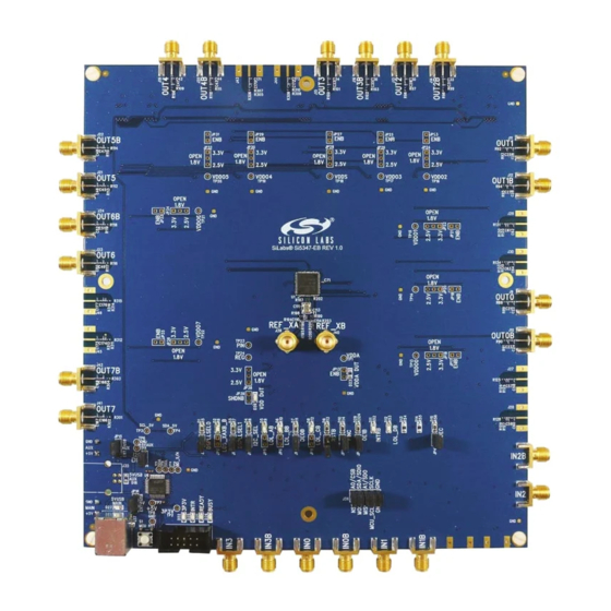
Figure 1. Si5347 Evaluation Board
Copyright © 2015 by Silicon Labs
Si 5 34 7 - EV B
U
'
G
SER
S
U I D E
EVB Features
Powered from USB port or external +5 V power
supply via screw terminals.
Onboard 48 MHz XTAL allows standalone or
holdover mode of operation on the Si5347.
CBPro
GUI programmable V
device supply voltages of 3.3, 2.5, or 1.8 V.
CBPro GUI programmable V
of the 8 outputs to have its own supply voltage
selectable from 3.3, 2.5, or 1.8 V.
CBPro GUI allows control and measurement of
voltage, current, and power of V
supplies.
Status LEDs for power supplies and control/status
signals of Si5347.
SMA connectors for input clocks, output clocks and
optional external timing reference clock.
supply allows
DD
supplies allow each
DDO
and all 8 V
DD
DDO
Si5347-EVB
Advertisement
Table of Contents

Related Manuals for Silicon Laboratories Si5347-EVB


Summary of Contents for Silicon Laboratories Si5347-EVB
- Page 1 VALUATION OARD U I D E Description EVB Features The Si5347-EVB is used for evaluating the Si5347 Powered from USB port or external +5 V power Quad Any-Frequency Jitter Attenuating Clock Multiplier. supply via screw terminals. The Si5347 contains 4 independent DSPLLs in a single Onboard 48 MHz XTAL allows standalone or ...
-
Page 2: Power Supply
1. Si5347-EVB Functional Block Diagram Below is a functional block diagram of the Si5347-EVB. This EVB can be connected to a PC via the main USB connector for programming, control, and monitoring. See section “3. Quick Start” for more information. -
Page 3: Quick Start
2. Connect USB cable from Si5347-EVB to PC with ClockBuilderPro software installed. 3. Leave the jumpers as installed from the factory, and launch the ClockBuilderPro software. 4. You can use ClockBuilderPro to create, download, and run a frequency plan on the Si5347-EVB. 5. For the Si5347 data sheet, go to http://www.silabs.com/timing. -
Page 4: Status Leds
Si5347-EVB 5. Status LEDs Table 2. Si5347-EVB Status LEDs Location Silkscreen Color Status Function Indication 5VUSBMAIN Blue Main USB +5 V present 3P3V Blue DUT +3.3 V is present VDD DUT Blue DUT VDD Core voltage present INTR MCU INTR (Interrupt) active... - Page 5 Si5347-EVB Figure 3. Si5347-EVB LED Locations Rev. 1.1...
-
Page 6: External Reference Input (Xa/Xb)
DSPLL and for providing a stable reference for the free-run and holdover modes. The Si5347-EVB can also accommodate an external reference clock instead of a crystal. To evaluate the device with an external REFCLK, C111 and C113 must be populated and XTAL Y1 removed (see Figure 4 below). -
Page 7: Clock Input Circuits (Inx/Inxb)
The Si5347-EVB provides pads for optional output termination resistors and/or low frequency capacitors. Note that components with schematic “NI” designation are not normally populated on the Si5347-EVB and provide locations on the PCB for optional dc/ac terminations by the end user. - Page 8 Si5347-EVB 9. Installing ClockBuilderPro (CBPro) Desktop Software To install the CBPro software on any Windows 7 (or above) PC: Go to http://www.silabs.com/CBPro and download ClockBuilderPro software. Installation instructions and User’s Guide for ClockBuilder can be found at the download link shown above. Please follow the instructions as indicated.
- Page 9 Si5347-EVB 10.2. Additional Power Supplies The Si5347-EB comes pre-configured with jumpers installed at JP15 and JP16 (pins 1-2 in both cases) in order to select “USB”. These jumpers, together with the components installed, configure the evaluation board to obtain all +5 V power solely through the main USB connector at J37.
- Page 10 Si5347-EVB 10.3. Overview of ClockBuilderPro Applications The ClockBuilderPro installer will install two main applications: Figure 9. Application #1: ClockbuilderPro Wizard Use the CBPro Wizard to: Create a new design Review or edit an existing design Export: create in-system programming files ...
- Page 11 Si5347-EVB 10.4. Common ClockBuilderPro Work Flow Scenarios There are three common workflow scenarios when using CBPro and the Si5347 EVB. These workflow scenarios are: Workflow Scenario #1: Testing a Silicon Labs-Created Default Configuration Workflow Scenario #2: Modifying the Default Silicon Labs-Created Device Configuration ...
- Page 12 Si5347-EVB Figure 14. Writing Design Status After CBPro writes the default plan to the EVB, click on “Open EVB GUI” as shown below. Figure 15. Open EVB GUI The EVB GUI will appear. Note all power supplies will be set to the values defined in the device’s default CBPro project file created by Silicon Labs, as shown below.
- Page 13 Si5347-EVB 10.5.1. Verify Free-Run Mode Operation Assuming no external clocks have been connected to the INPUT CLOCK differential SMA connectors (labeled “INx/INxB”) located around the perimeter of the EVB, the DUT should now be operating in free-run mode, as the DUT will be locked to the crystal in this case.
- Page 14 Si5347-EVB Your configuration’s design report will appear in a new window, as shown below. Compare the observed output clocks to the frequencies and formats noted in your default project’s Design Report. Figure 19. Design Report Window 10.5.2. Verify Locked Mode Operation Assuming you connect the correct input clocks to the EVB (as noted in the Design Report shown above), the DUT on your EVB will be running in “locked”...
- Page 15 Si5347-EVB 10.6. Workflow Scenario #2: Modifying the Default Silicon Labs-Created Device Configuration To modify the “default” configuration using the CBPro Wizard, click on Edit Configuration with Wizard: Figure 20. Edit Configuration with Wizard You will now be taken to the Wizard’s step-by-step menus to allow you to change any of the default plan’s operating configurations.
- Page 16 Si5347-EVB Figure 22. Writing Design Status 10.7. Workflow Scenario #3: Testing a User-Created Device Configuration To test a previously created user configuration, open the CBPro Wizard by clicking on the icon on your desktop and then selecting Open Design Project File.
- Page 17 Si5347-EVB Locate your CBPro design file (*.slabtimeproj or *.sitproj file) in the Windows file browser. Figure 24. Browse to Project File Select Yes when the WRITE DESIGN to EVB popup appears: Figure 25. Write Design to EVB Dialog The progress bar will be launched. Once the new design project file has been written to the device, verify the presence and frequencies of your output clocks and other operating configurations using external instrumentation.
- Page 18 Si5347-EVB 10.8. Exporting the Register Map File for Device Programming by a Host Processor You can also export your configuration to a file format suitable for in-system programming by selecting Export as shown below: Figure 26. Export Register Map File You can now write your device’s complete configuration to file formats suitable for in-system programming.
-
Page 19: Writing A New Frequency Plan Or Device Configuration To Non-Volatile Memory (Otp)
Interface) link. The MCU is the SPI master and the Si5347 device is the SPI slave. The Si5347 device can also support a 2-wire I2C serial interface, although the Si5347-EVB does NOT support the I2C mode of operation. SPI mode was chosen for the EVB because of the relatively higher speed transfers supported by SPI vs. I2C. - Page 20 The Si5347 EVB Schematic and Bill of Materials (BOM) can be found online at: http://www.silabs.com/products/clocksoscillators/pages/si538x-4x-evb.aspx Note: Please be aware that the Si5347-EVB schematic is in OrCad Capture hierarchical format and not in a typical “flat” sche- matic format. Rev. 1.1...
- Page 21 The products must not be used within any Life Support System without the specific written consent of Silicon Laboratories. A "Life Support System" is any product or system intended to support or sustain life and/or health, which, if it fails, can be reasonably expected to result in significant personal injury or death.
Need help?
Do you have a question about the Si5347-EVB and is the answer not in the manual?
Questions and answers