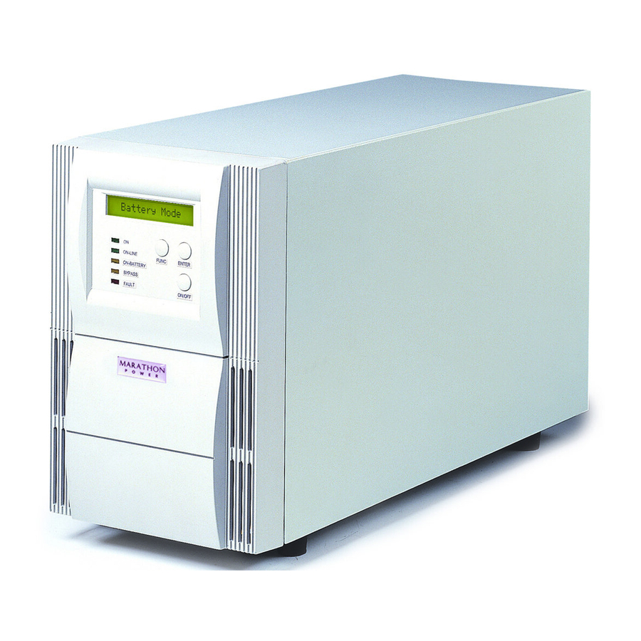
Marathon Power vault series User Manual
True on line double conversion
Hide thumbs
Also See for vault series:
- User manual (51 pages) ,
- User manaul (36 pages) ,
- User manual (32 pages)

Subscribe to Our Youtube Channel
Related Manuals for Marathon Power vault series


Summary of Contents for Marathon Power vault series
- Page 1 Vault Series True On Line, Double Conversion Uninterruptible Power Supply USER MANUAL FOR MODELS: 700VA - 3000VA...
-
Page 3: Table Of Contents
Table of Contents Section Page 1. Introduction ..........................5 2. System Description .........................5 2.1 General Description ......................5 2.2 System Configuration ......................6 3. Safety Information ........................7 4. Storage .............................7 5. Installation ..........................8 5.1 Environment and Mounting Options ................8 - 11 5.2 Rear Panel Views .......................12 - 16 5.2.a Tower Models - 700 / 1K / 1.5KVA Rear Panel View ..........12 5.2.b Tower Models - 2K / 3KVA Rear Panel View .............13 5.2.c 19”... -
Page 4: Declaration Of Conformity Request
EMC Statements FCC Part 15 NOTICE: Pursuant to section 15 of the FCC rules, this product has been tested and thereby complies with the conditions of a Class B (700-2000VA) and Class A (3000VA) digital device, which have been established for offering sufficient protection against dangerous interference for installation in a residential area. -
Page 5: Important Safety Instructions
IMPORTANT SAFETY INSTRUCTIONS SAVE THESE INSTRUCTIONS 1. T his Manual Contains Important Instructions that should be followed during Installation and Maintenance of the UPS and Batteries. 2. T he equipment can be operated by any individual. No previous experience is required. 3. - Page 6 The instructions contained within this safety manual are extremely important and should be closely followed at all times during installation and follow-up maintenance of the UPS and batteri. CAUTION The unit contains dangerous voltage levels. If the UPS is on, but not connected to an AC power supply, the unit’s outlets may still be energized with voltage due to the presence of an internal power source, i.e.
-
Page 7: Introduction
1. Introduction The information provided in this manual refers to our single phase, 700VA through 3000VA, true on-line uninterruptible power supplies. It covers basic functions, operating and installation instructions, cautionary notes and detail on how to ship, store and handle them. Installation must be carried out in accordance with this manual as well as local electrical regulations and should only be performed by qualified personnel to avoid the risk of electric shock or damage to the unit. -
Page 8: System Configuration
Efficiency Optimizer The Efficiency Optimizer is a unique feature that reduces long-term cost of ownership by minimizing power loss and reducing power consumption thereby making the entire system extremely efficient. Simply put, the UPS automatically alternates between bypass and on-line modes depending upon the condition of the incoming AC power. -
Page 9: Safety Information
3. Safety Information PLEASE READ THIS SECTION TO AVOID RISK OF SHOCK OR OTHER HAZARDOUS SITUATIONS. 1. Please handle the unit with extreme caution since the batteries contain large amounts of energy. Always store the unit in the orientation marked on the packaging. 2. -
Page 10: Installation
5. Installation 5.1 System Configuration and Sizing The internal electronics of the UPS plus the internal battery or batteries constitute the system. Please make sure that the following factors have been taken into consideration: 1. The total demand of the protected load determines the UPS power (VA) requirements. Allow some margin or headroom for future expansion or power requirement calculation inaccuracies. - Page 11 Vertical and Wall-Mount Installation The following diagrams illustrate how to install or mount the UPS (and battery packs when applicable) in either vertical or wall-mount applications: Vertical Installation Wall-Mount Installation...
- Page 12 19” Rack-Mount Installation The following diagrams illustrate how to install or mount the UPS (and battery packs when applicable) in 19” rack-mount applications: Lower Side Rail Installation Rear Bracket Installation...
- Page 13 Unit Stack Installation The following diagrams illustrate how to stack the units (and battery packs when applicable): Stack Installation...
-
Page 14: Rear Panel Views
5.2 Rear Panel Views 5.2a Tower Models 700 / 1K / 1.5KVA Rear Panel Views (120V NEMA) (220V G TYPE) Rear View 1 Rear View 2 (220V IEC) (220V NEMA) Rear View 3 Rear View 4 VTWE-0700-01 ..Rear View 1 VTWE-1000-01 .. -
Page 15: Tower Models - 2K / 3Kva Rear Panel View
5.2b Tower Models 2K / 3KVA Rear Panel Views (120V NEMA) (220V G TYPE) Rear View 6 Rear View 7 (220V IEC) (220V NEMA) Rear View 8 Rear View 9 VTWE-2000-01 ..Rear View 6 VTWE-3000-01 ..Rear View 6 VTWE-2000-02 .. -
Page 16: C 19" Rack-Mount Models (1U) - 700 / 1Kva Rear Panel View
5.2c 19” Rack Mount Models (1U) 700 / 1KVA Rear Panel Views (RM-1U 120V NEMA) Rear View 11 (RM-1U 220V NEMA) Rear View 12 (RM-1U 220V IEC) Rear View 13 VRME-0700-01 ..Rear View 11 VRME-1000-01 ..Rear View 11 VRME-0700-02 .. -
Page 17: D 19" Rack-Mount Models (2U) - 700 / 1K / 1.5Kva Rear Panel View
5.2d 19” Rack Mount Models (2U) 700 / 1K / 1.5KVA Rear Panel Views (RM-2U 120V NEMA) Rear View 14 (RM-2U 220V IEC) Rear View 15 (RM-2U 220V G-TYPE) Rear View 16 (RM-2U 220V NEMA) Rear View 17 A hardwire version of all models is available. For model number, substitute the last two digits for H1 (120V) or H2 (220V). VRTE-0700-01 .. -
Page 18: E 19" Rack-Mount Models (1U) - 2K / 3Kva Rear Panel View
5.2e 19” Rack Mount Models (2U) 2K / 3KVA Rear Panel Views (RM-2U 120V NEMA) Rear View 18 (RM-2U 220V IEC) Rear View 19 (RM-2U 220V G-TYPE) Rear View 20 (RM-2U 220V NEMA) Rear View 21 (HARDWIRE TERMINAL) Rear View 22 A hardwire version of all models is available. -
Page 19: Ac Power And Load Connection
5.3 AC Power and Load Connections Various input (and sometimes output) cables are supplied with all models: 1. Ensure that the UPS is disconnected from the AC power supply when connecting External Battery Packs. 2. Use the battery cable that is supplied with the External Battery Pack when connecting it to the UPS. -
Page 20: Connecting An Extended Run-Time Battery Pack
5.4 Connecting an Extended Run-Time Battery Pack Please refer to the Extended Run-Time Battery Pack user manual for detailed instructions. 5.5 Factory Default Settings The following table shows the factory default settings for all UPS parameters as well as user selectable options. -
Page 21: Rs-232 Interface Port
6.3 RS-232 Interface Port (Standard) The RS-232 interface uses a 9-pin female D-sub connector. This information consists of data regarding utility (AC) power, the load and the UPS. The interface port pins and their functions are identified in the following table: Pin# Signal Direction (UPS) -
Page 22: Operational Instructions
7. Operational Instructions 7.1 Starting Up and Shutting Down the UPS Start Up 1. Ensure that the unit has been correctly installed and that the input power cable is connected to a properly grounded AC outlet. 2. The unit is turned on by pushing the power push-button on the front panel for more than 3 seconds. -
Page 23: Control Panel Indicators
7.3 Control Panel Indicators Status, parameters and readings are displayed on the control panel via five LED indicators and/ or an LCD screen and audible alarms compliment the display. This symbol is accompanied by a green LED that illuminates when the UPS has been turned on. -
Page 24: Lcd Panel Display Modes
7.4 LCD Panel Display Modes 1. Normal Display Mode UPS status is shown in this display mode. From this mode, the UPS data display mode and the setting display mode can be selected by pressing the appropriate push-button. 2. Data Display Mode Various data and measurements are shown in this display mode. -
Page 25: Manual Ups Or Battery Test
Settings LCD Display Detail Selection/Option Default 208/220/230/240 V 230V Output Voltage O/P V Setting Nominal Voltage Selection 100/110/115/120/127 V 110V ±2% Input frequency range selection when ±5% ±5% Input/Frequency I/P F Setting UPS is in free run mode ±7% ±10% Input Voltage range selection when Input/Bypass +10/-15%... -
Page 26: Audible Alarms
7.6 Audible Alarms 1. If the UPS is on battery and the “ON BATTERY” LED is illuminated, the unit will beep every 5 seconds. 2. If the battery capacity is low and the “ON BATTERY” LED is flashing, the unit will beep twice every 5 seconds. -
Page 27: Troubleshooting
7.7 Trouble shooting Corrective Action LCD Dis. Audible Alar. Problem Description Output Two beeps per The UPS is overloaded (in Reduce the load on the UPS by Overload second Line Mode). The power rating disconnecting less critical equipment. of the connected equipment Once the total load is below the exceeds the capacity (VA maximum specified by the UPS, it will... -
Page 28: Maintenance
8. Maintenance As long as all the installation, environmental and operational requirements have been followed and met, the UPS will require little or no maintenance for many years. The batteries are the only component that should eventually need replacing. Their useful life depends primarily on the following two factors;... -
Page 29: Storage Requirements
Battery Replacement Procedure Diagram for Tower Models Step 1 Step 2 Step 3 CAUTION: Take care when removing the front cover as there is a ribbon cable attached to the cover from the UPS! Fig.4 Battery Replacement Procedure Diagram for 19” Rack-Mount Models Step 1 Step 2 Step 3... -
Page 30: Specifications
9. Specifications 9.1 120V Models GENERAL Rated Capacity: 700VA, 1000 VA, 1500 VA, 2000 VA, 3000 VA with a power factor of 0.7 Technology: True on-line, double conversion topology with integral automatic bypass INPUT Phase: Single phase plus ground Input Bypass Voltage: 96 - 138 VAC (+15% to -20% of 120V nominal - user selectable) Input Voltage range: 60 / 70 / 80VAC - 144 VAC... - Page 31 9.3 All Models ENVIRONMENTAL Ambient temperature range: +32 °F to +104°F (+0 °C to +40 °C) Optimum temperature range: +59 °F to +77°F (+15 °C to +25 °C) Storage temperature: +5 °F to +122°F (-15 °C to +50 °C) Cooling: Forced air cooling Humidity: 0-95%, non-condensing...
- Page 32 230V Tower Models: Model # VTWE-0700-02* VTWE-1000-02* VTWE-1500-02* VTWE-2000-02* VTWE-3000-02* Capacity 700VA / 490W 1000VA / 700W 1500VA / 1050W 2000VA / 1400W 3000VA / 2100W Input Connection IEC 320 (10A) IEC 320 (16A) 4 x IEC 320 (10A) 8 x IEC 320 (10A), 1 x IEC 320 (16A) Output Connection 4 x NEMA 5-15R 12 x NEMA 5-15R...
- Page 33 120V Tower Models: Model # VTWE-0700-01* VTWE-1000-01* VTWE-1500-01* VTWE-2000-01* VTWE-3000-01* Capacity 700VA / 490W 1000VA / 700W 1500VA / 1050W 2000VA / 1400W 3000VA / 2100W Input Connection Fixed Power Cord Output Connection 6 x NEMA 5-15R 6 x NEMA 5-15R Sealed, lead-acid Sealed, lead-acid Sealed, lead-acid...
-
Page 34: Warranties
Marathon Power warrants to the original purchaser, who must have properly registered the product within 30 days of purchase, and not for the benefit of anyone else that this product at the time of its sale by Marathon Power is free of defects in materials and workmanship for three (3) years (batteries for 2 years within the USA, Canada and Mexico, otherwise 1 year) from the original purchase date. - Page 36 Marathon Power, Inc. 2016 2538 E. 54th Street Huntington Park, CA 90255 Office: 310-689-2328 Fax: 310-689-2329 support@marathon-power.com www.marathon-power.com Vault700_3kVA_UserMan_Rev3 Marathon Power Inc. 2016 ©...
Need help?
Do you have a question about the vault series and is the answer not in the manual?
Questions and answers