Table of Contents
Advertisement
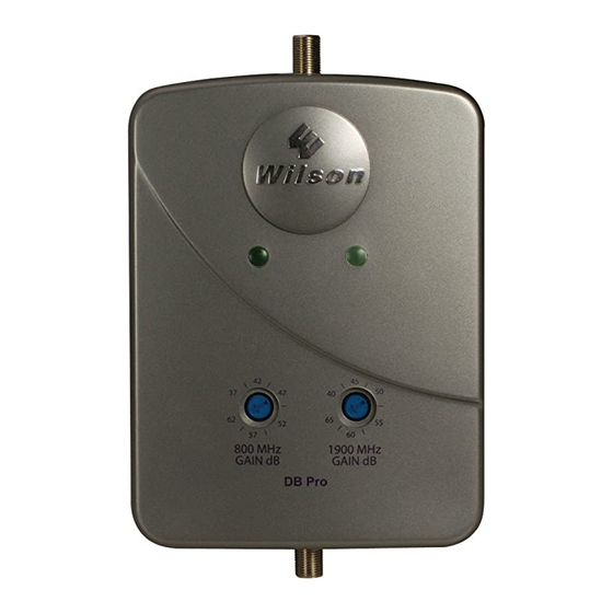
DB Pro
™
Adjustable Gain
In-Building Wireless
800/1900 MHz
Smart Technology ™
Signal Booster
Contents:
How it Works . . . . . . . . . . . . . . . . . . . . . . . . . . . . . . . . . . . . . . 1
Quick Install Overview . . . . . . . . . . . . . . . . . . . . . . . . . . . . . . . 2
Installation Diagram . . . . . . . . . . . . . . . . . . . . . . . . . . . . . . . . . 3
Installing the Outside Antenna . . . . . . . . . . . . . . . . . . . . . . . . . 5
Finding the Strongest Signal . . . . . . . . . . . . . . . . . . . . . . . . . . 7
Installing the Inside Antenna . . . . . . . . . . . . . . . . . . . . . . . . . . 8
Installing a Wilson Electronics Signal Booster . . . . . . . . . . . . . 9
Powering up a Wilson Electronics Signal Booster . . . . . . . . . . 9
Understanding the Signal Booster Lights . . . . . . . . . . . . . . . 10
Warnings & Recommendations . . . . . . . . . . . . . . . . . . . . . . . 12
Signal Booster Specifications . . . . . . . . . . . . . . . . . Back Cover
Appearance of device and accessories may vary .
Note: This manual contains important safety and operating information . Please read and
follow the instructions in this manual . Failure to do so could be hazardous and result in
damage to your Signal Booster .
Wilson
Electronics, Inc.
®
Advertisement
Table of Contents

Related Manuals for Wilson Electronics DB Pro 271265


Summary of Contents for Wilson Electronics DB Pro 271265
-
Page 1: Table Of Contents
Installing the Inside Antenna . . . . . . . . . . . . . . . . . . . . . . . . . . 8 Installing a Wilson Electronics Signal Booster . . . . . . . . . . . . . 9 Powering up a Wilson Electronics Signal Booster . -
Page 2: How It Works
Installation Instructions for the Following Wilson Quick Install Overview Electronics Signal Booster: See Installation Diagram on pages 3 & 4 . Contact Wilson Electronics Technical Support Team with any questions at 866-294-1660 . DB Pro™ Adjustable Gain In-Building Wireless 800/1900 MHz Smart Technology ™ Signal Booster... -
Page 3: Installation Diagram
AG DB Pro Installation Diagram Before Getting Started This guide will help you properly install your Wilson Electronics Signal Booster . It is important to read through all of the installation steps for your particular application prior to installing any equipment. - Page 4 Antenna. See Figure 1 & 2 on page 10. clearance in all directions around it . Position the antenna so that it has Contact Wilson Electronics Technical Support Team with any questions at 866-294-1660 Contact Wilson Electronics Technical Support Team with any questions at 866-294-1660 or email: tech@wilsonelectronics.com.
-
Page 5: Installation Diagram
3-way Contact Wilson Electronics Technical Support Team with any questions at 866-294-1660 Contact Wilson Electronics Technical Support Team with any questions at 866-294-1660 or email: tech@wilsonelectronics.com. Hours: 7 am to 6 pm MST. -
Page 6: Installing A Wilson Electronics Signal Booster
Support hours are 7 am to 6 pm MST . Booster has protection shutoff circuits to prevent the disruption of Contact Wilson Electronics Technical Support Team with any questions at 866-294-1660 Contact Wilson Electronics Technical Support Team with any questions at 866-294-1660 or email: tech@wilsonelectronics.com. -
Page 7: Warnings & Recommendations
15 minute installation period and the unit is powered up and working properly . Contact Wilson Electronics Technical Support Team with any questions at 866-294-1660 Contact Wilson Electronics Technical Support Team with any questions at 866-294-1660 or email: tech@wilsonelectronics.com. Hours: 7 am to 6 pm MST. - Page 8 . However, no responsibility is assumed company’s 55,000-square-foot headquarters in St . George, Utah . Wilson by Wilson Electronics, Inc . for any business or personal losses arising from its Electronics has product dealers in all 50 states as well as in countries use, or for any infringements of patents or other rights of third parties that may result from its use .
-
Page 9: Signal Booster Specifications
Signal Booster Specifications IC: 4726A-271265 DB Pro FCC ID: PWO271265 Specifications Model Number 271265 Antenna connectors F-Female Antenna impedance 75 ohms 6 .5 x 4 .5 x 1 .75 inch Dimensions (16 .5 x 11 .4 x 4 .4 cm) Weight 0 .47 lbs (0 .213 kg) Frequency...
Need help?
Do you have a question about the DB Pro 271265 and is the answer not in the manual?
Questions and answers