Table of Contents
Advertisement
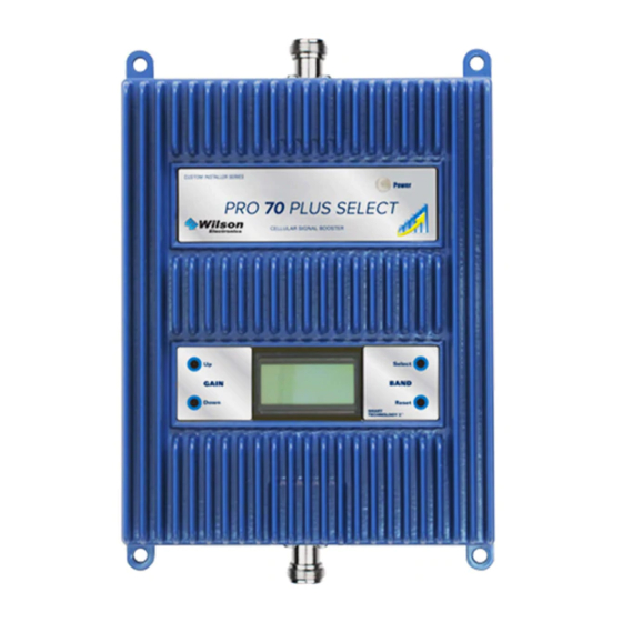
PRO SERIES
Contents:
How Cellular Boosters Work . . . . . . . . . . . . . . . . . . . . . . . . . . . . . . . . . . 1
Inside This Package . . . . . . . . . . . . . . . . . . . . . . . . . . . . . . . . . . . . . . . . 2
Install Overview . . . . . . . . . . . . . . . . . . . . . . . . . . . . . . . . . . . . . . . . . . . . 2
Installation Diagram . . . . . . . . . . . . . . . . . . . . . . . . . . . . . . . . . . . . . .3 & 4
Outside Antenna Installation . . . . . . . . . . . . . . . . . . . . . . . . . . . . . . . . . . 5
Installing the Inside Panel Antenna(s) . . . . . . . . . . . . . . . . . . . . . . . . . . . 7
Installing The Signal Booster . . . . . . . . . . . . . . . . . . . . . . . . . . . . . . . . . . 7
Finding The Strongest Signal . . . . . . . . . . . . . . . . . . . . . . . . . . . . . . . . . 8
Post Install Setup / LCD Screen . . . . . . . . . . . . . . . . . . . . . . . . . . . . . . . 9
Warnings and Recommendations . . . . . . . . . . . . . . . . . . . . . . . . . . . . . 13
Warranty . . . . . . . . . . . . . . . . . . . . . . . . . . . . . . . . . . . . . . . . . . . . . . . . 16
Specifications . . . . . . . . . . . . . . . . . . . . . . . . . . . . . . . . . . . . . Back page
Appearance of device and accessories may vary .
Note: This manual contains important safety and operating information . Please read and follow the
instructions in this manual . Failure to do so could result in damage to your Signal Booster .
INSTALLATION GUIDE
PRO 70 PLUS SELECT
In-Building
SmarTech
Cellular Signal Boosters
®
Advertisement
Table of Contents

Related Manuals for Wilson Electronics PRO 70 PLUS SELECT


Summary of Contents for Wilson Electronics PRO 70 PLUS SELECT
-
Page 1: Table Of Contents
PRO SERIES INSTALLATION GUIDE PRO 70 PLUS SELECT In-Building SmarTech ® Cellular Signal Boosters Contents: How Cellular Boosters Work . . . . . . . . . . . . . . . . . . . . . . . . . . . . . . . . . . 1 Inside This Package . -
Page 2: How Cellular Boosters Work
. Refer to pages 9-11 for explanation of the booster status display . Contact Wilson Electronics Customer Support Team with any questions at 866-839-9361 or email: tech@wilsonelectronics.com. Mon.- Fri. Hours: 7 am to 6 pm MST. -
Page 3: Inside This Package
For additional antenna options see pages 14 & 15. Install Overview Refer to Installation Diagram on page 3 & 4 . Contact Wilson Electronics Technical Support Team with any questions at 866-839-9361 1 . Select a location on the roof or outside of the building to install the outside antenna . -
Page 4: Installation Diagram
Inside Antenna in the ceiling facing down for the best coverage . Power Supply Surge Protector Power Strip Contact Wilson Electronics Customer Support Team with any questions at 866-839-9361 or email: tech@wilsonelectronics.com. Mon.- Fri. Hours: 7 am to 6 pm MST. - Page 5 2-way or 3-way, when using multiple inside antennas for increased coverage Optional Inside Antenna for added coverage Signal Booster Contact Wilson Electronics Customer Support Team with any questions at 866-839-9361 or email: tech@wilsonelectronics.com. Mon.- Fri. Hours: 7 am to 6 pm MST.
-
Page 6: Outside Antenna Installation
Inside Panel Inside Panel Antenna Antenna Antenna Outdoor Antenna Signal Booster Signal Booster Figure 2 Figure 1 Contact Wilson Electronics Customer Support Team with any questions at 866-839-9361 or email: tech@wilsonelectronics.com. Mon.- Fri. Hours: 7 am to 6 pm MST. - Page 7 . In this circumstance, the cable will be accessible in the attic for further routing . Contact Wilson Electronics Customer Support Team with any questions at 866-839-9361 or email: tech@wilsonelectronics.com.
-
Page 8: Installing The Inside Panel Antenna(S)
. Attic installations may expose the booster to high heat . Contact Wilson Electronics Customer Support Team with any questions at 866-839-9361 or email: tech@wilsonelectronics.com. Mon.- Fri. Hours: 7 am to 6 pm MST. -
Page 9: Finding The Strongest Signal
Signal readings usually appear as a negative number (for example, -86) . The closer the number to zero, the stronger the signal (see Signal Srength Graph above) . Contact Wilson Electronics Customer Support Team with any questions at 866-839-9361 or email: tech@wilsonelectronics.com. -
Page 10: Post Install Setup / Lcd Screen
The 1900 MHz 1700/2100 MHz The 800 MHz Band – PCS Band – AWS Band – Cell Band Contact Wilson Electronics Customer Support Team with any questions at 866-839-9361 or email: tech@wilsonelectronics.com. Mon.- Fri. Hours: 7 am to 6 pm MST. - Page 11 . Contact Wilson Electronics Customer Support Team with any questions at 866-839-9361 or email: tech@wilsonelectronics.com. Mon.- Fri. Hours: 7 am to 6 pm MST.
- Page 12 . If the Signal Booster will not respond, relocation of the outside antenna may be required . 2 . If the light remains orange, contact the Wilson Electronics Customer Support Team for assistance at 866-839-9361 .
- Page 13 . All products are engineered and assembled in the company’s 100,000 square-foot headquarters in St . George, Utah . Wilson Electronics has product dealers in all 50 states as well as in countries around the world .
-
Page 14: Warnings And Recommendations
This device complies with Part 15 of FCC rules . Operation is subject to two conditions: (1) This device may not cause harmful interference, and (2) this device must accept any interference received, including interference that may cause undesired operation . Changes or modifications not expressly approved by Wilson Electronics could void the authority to operate this equipment . - Page 15 • 25’ RG58 Cable • N-Male to F-Female adapter Kit 314411-5825 • 50 Ohm Wide Band Directional Contact Wilson Electronics Customer Support Team with any questions at 866-839-9361 or email: tech@wilsonelectronics.com. Mon.- Fri. Hours: 7 am to 6 pm MST.
- Page 16 • N-Male to F-Female adapter Kit 311124-1180 • 1900 MHz Yagi Directional • 80’ RG11 Cable • N-Male to F-Female adapter Contact Wilson Electronics Customer Support Team with any questions at 866-839-9361 or email: tech@wilsonelectronics.com. Mon.- Fri. Hours: 7 am to 6 pm MST.
-
Page 17: Warranty
Returned Material Authorization (RMA) number supplied by Wilson Electronics . Wilson Electronics shall, at its option, either repair or replace the product . Wilson Electronics will pay for delivery of the repaired or replaced product back to the original consumer if located within the continental U .S . - Page 18 Notes: _____________________________________________________________ _____________________________________________________________ _____________________________________________________________ _____________________________________________________________ _____________________________________________________________ _____________________________________________________________ _____________________________________________________________ _____________________________________________________________ _____________________________________________________________ _____________________________________________________________ _____________________________________________________________ _____________________________________________________________ _____________________________________________________________ _____________________________________________________________ _____________________________________________________________ _____________________________________________________________ _____________________________________________________________ _____________________________________________________________ _____________________________________________________________ _____________________________________________________________ _____________________________________________________________ _____________________________________________________________ _____________________________________________________________ _____________________________________________________________ _____________________________________________________________ _____________________________________________________________ _____________________________________________________________...
- Page 19 Notes: _____________________________________________________________ _____________________________________________________________ _____________________________________________________________ _____________________________________________________________ _____________________________________________________________ _____________________________________________________________ _____________________________________________________________ _____________________________________________________________ _____________________________________________________________ _____________________________________________________________ _____________________________________________________________ _____________________________________________________________ _____________________________________________________________ _____________________________________________________________ _____________________________________________________________ _____________________________________________________________ _____________________________________________________________ _____________________________________________________________ _____________________________________________________________ _____________________________________________________________ _____________________________________________________________ _____________________________________________________________ _____________________________________________________________ _____________________________________________________________ _____________________________________________________________ _____________________________________________________________ _____________________________________________________________...
-
Page 20: Specifications
Signal Booster Specifications Pro 70 Plus Select Model Number U462027 FCC ID PWO460027 IC ID 4726A-460027 Connectors N-F emale Antenna Impedance 50 Ohms Frequency 698-716 MHz, 746-787 MHz, 824-894 MHz, 1850-1995 MHz, 1710-1755/2110-2155 MHz Band12/17 Band13 1700/2100 1900 Passband Gain (nominal) 56 .0...
Need help?
Do you have a question about the PRO 70 PLUS SELECT and is the answer not in the manual?
Questions and answers