Pfaff 335 Instruction Manual
Hide thumbs
Also See for 335:
- Instruction manual (62 pages) ,
- Adjustment manual (36 pages) ,
- Instruction manual (44 pages)

Subscribe to Our Youtube Channel
Related Manuals for Pfaff 335


Summary of Contents for Pfaff 335
-
Page 1: Instruction Manual
Instruction manual This instruction manual applies to machines from the following serial numbers onwards: # 2432978 296-12-18 393/002 Betriebsanleitung engl. 10.00... - Page 2 This Instruction manual is valid for all models and subclasses listed in the chapter „Specifications“ . The reprinting, copying or translation of PFAFF Instruction Manuals, whether in whole or in part, is only permitted with our previous permission and with written reference to the source.
-
Page 3: Table Of Contents
Danger symbols .................... 1 - 5 Proper use ...................2 - 1 Specifications ................3 - 1 PFAFF 335 ....................3 - 1 Possible models and subclasses ..............3 - 1 Disposal of the machine ..............4 - 1 Transport, packaging and storage ............ 5 - 1 Transport to the customer’s premises ............ - Page 4 Contents .01.05 Mounting the sewing lamp ................8 - 4 .01.06 Mounting the spool holder ................8 - 4 Initial operation ..................... 8 - 4 Switching the machine on/off ............... 8 - 4 Preparation .................. 9 - 1 Needle and thread ..................9 - 1 Inserting the needle ..................
- Page 5 Contents .04.08 Needle thread tension release ..............11 - 10 .04.09 Thread check spring ................... 11 - 11 .04.10 Bobbin winder .................... 11 - 12 .04.11 Regulating the pressure on the presser foot ..........11 - 13 Adjusting the thread trimmer -800/52 ............ 11 - 14 .05.01 Preadjusting the control cam ..............
-
Page 6: Safety
Safety Safety 1.01 Directives This machine is constructed in accordance with the European regulations contained in the conformity and manufacturer’s declarations. In addition to this Instruction Manual, observe also all generally accepted, statutory and other regulations and legal requirements -including those of the country and all valid environ- mental protection regulations! The regionally valid regulations of the social insurance society for occupational accidents or other supervisory organisations are to be strictly adhered to! -
Page 7: Safety Symbols
It is the obligation of the operator to ensure that none of the safety mechanisms are removed or deactivated. It is the obligation of the operator to ensure that only authorised persons operate and work on the machine. Further information can be obtained at your PFAFF agent. 1 - 2... -
Page 8: Operating And Specialist Personnel
Safety Operating and specialist personnel Operating personnel 05.01 Operating personnel are persons responsible for the equipping, operating and cleaning of the machine as well as taking care of faults arising in the sewing area. The operating personnel is obliged to observe the following points and must: always observe the Notes on Safety in the Instruction Manual. -
Page 9: Danger Symbols
Safety Danger symbols A working area of 1 metre is to be kept free both in front of and behind the machine while it is in operation so that it is always easily accessible. Never reach into the sewing area while sewing! Danger of injury by the needle! Never leave objects on the table or in the needle plate area while adjusting the machine settings! Objects can become trapped or be slung away! Danger of injury! - Page 10 Safety Do not operate the machine without the belt guard 4! Danger of injury by the rotating V-belt! Fig. 1 - 03 1 - 5...
-
Page 11: Proper Use
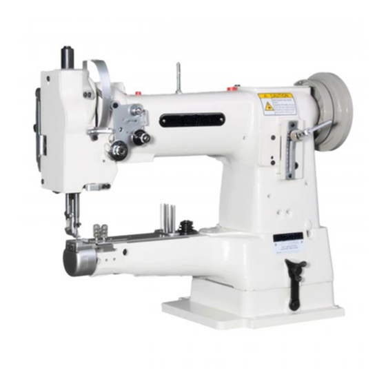
Proper use Proper use The PFAFF 335 is a single needle, free-arm sewing machine with bottom, top and needle feeds for sewing lockstitch seams. Any and all uses of this machine which have not been approved of by the manufacturer are considered to be inappropriate! The manufacturer cannot be... -
Page 12: Specifications
Specifications Specifications PFAFF 335 Stitch type: ....................... 301 ( lockstitch) Model: ............................ B Needle system: ......................134 - 35 Needle thickness (Nm) in 1/100 mm: ................80 - 100 Max. stitch length: on sub classes -2/77; -6/01; -17/01; -39/21; -40/64; -155/01 .......... 4.5 mm on sub class -40/63 (model N 2.5) ................ -
Page 13: Disposal Of The Machine
Disposal of the machine Disposal of machine waste The proper disposal of machine waste is the responsibility of the customer. The materials used on the machines are steel, aluminium, brass and various plastics. The electrical equipment consists of plastics and copper. The machine waste is to be disposed of in accordance with the locally valid environmental protection regulations. -
Page 14: Transport, Packaging And Storage
Transport, packaging and storage Transport, packaging and storage Transport to the customer’s premises Within Germany, complete machines (with table and motor) are delivered without packaging. Machines without table and motor (machine heads only) and machines for export are packaged. Transport within the customer’s premises The manufacturer carries no liability for transport within the customer’s premises. -
Page 15: Explanation Of The Symbols
Explanation of the symbols Explanation of the symbols In the following section of this Instruction Manual, certain tasks or important pieces of information are accentuated by symbols. The symbols used have the following meanings: Note, information Cleaning, care Servicing, repairing, adjustment, maintenance (only to be carried out by specialist personnel) Lubrication, greasing 6 - 1... -
Page 16: On/Off Switch
Elements of operation Elements of operation On/Off switch Turn the machine on and off by pressing the On/Off switch 1. When the machine is turned on, the control lamp in the switch lights up. The On/Off switch pictured in the illustration is to be found on machines with Quick motors. -
Page 17: Stitch-Length Adjustment Lever/Reverse Sewing
Elements of operation Stitch-length adjustment lever / reverse sewing Adjust the stitch length by turning the milled nut 1 as required. Reverse sewing Raise the milled nut 1 as far as possible (position “R“). Fig. 7 - 03 Adjustment nut for the top feed lift Turn the machine off! Open cover 1 on the back of the machine, loosen nut 1 and move it as... -
Page 18: Mounting And Initial Operation
Mounting and initial operation Mounting and initial operation This machine may only be mounted and put into operation by qualified specialists! All relevant safety regulations are to be adhered to! Connections for electrical and compressed air supplies must be available at the machine’s location (see chapter 3: Specifications). -
Page 19: Tightening The V-Belt
Mounting and initial operation Tightening the V-belt .01.02 Loosen nuts 1. Tighten the V-belt using the dolly switch 2. Tighten nuts 1. Fig. 8 - 02 Fig. 8-02 shows a Quick motor. If another motor is used proceed as described in the instruction manual! 8 - 2... -
Page 20: Mounting The Upper V-Belt Guard
Mounting and initial operation Mounting the upper V-belt guard .01.03 Attach the two upper segments of the V-belt guard 1 and 2 using screws 5. Then screw the two lower segments of the lower V-belt guard 3 and 4 onto the table top with screws 6. -
Page 21: Mounting The Sewing Lamp
Mounting and initial operation Mounting the sewing lamp .01.05 Screw the sewing lamp onto the table top (wood screws 5x35) and have it connected by a specialist. Mounting the spool holder .01.06 Mount the spool holder. Insert the spool holder into the hole in the table top and affix it with the enclosed nuts. Initial operation Before operating the machine, check the electrical and pneumatic connections for possible damage. -
Page 22: Preparation
Preparation Preparation All regulations and instructions in this Instruction manual are to be observed. Special attention should be paid to the safety regulations! Preparation work is only to be carried out by appropriately trained personnel. The machine must always be separated from the power supply by switching off the on/off switch or by removing the mains plug from the power supply when carrying out preparation work! Needle and thread... -
Page 23: Inserting The Needle
Preparation Inserting the needle Switch off the machine! Loosen the needle retaining screw 1. Insert the needle as far as possible (The long groove in the needle must be pointing to the left). Retighten the needle retaining screw 1. Fig. 9 - 01 Winding the bobbin thread, adjusting the thread tension Fig. -
Page 24: Removing The Bobbin Case, Threading The Bobbin Case
Preparation Removing the bobbin case, threading the bobbin case Switch the machine off! Removing the bobbin case. Lift the retainer 1 and remove the bobbin case 2. Threading the bobbin case. Thread the bobbin in accordance with Fig. 9-04. The bobbin must rotate in the direction the arrow when the thread is pulled. -
Page 25: Threading The Needle Thread
Preparation Fig. 9 - 05 Threading the needle thread Switch the machine off! Thread the machine in accordance with Fig. 9-05, taking care to ensure that the needle is threaded from the left (see arrow). Adjusting the needle thread tension Adjust tension 1 so that the stitch loops are inside the sewing material. -
Page 26: Care And Maintenance
Care and maintenance Care and maintenance Servicing intervals Cleaning ............daily, more often if in continuous operation General lubrication ..................twice weekly Lubricating the sewing head ................. twice weekly Lubricating the hook ....................daily Checking the air pressure ............daily before starting sewing Water container of the service unit ........ -
Page 27: General Lubrication
/s at 40°C and a density of 0.865 g/cm at 15°C! We recommend PFAFF sewing machine oil. Part no. 280-1-120 144. Switch off the machine! Oil all of the bearings which are marked in Fig. 10-02 and 10-03 twice a week. -
Page 28: Lubricating The Sewing Head
Only use oil with a mean viscosity of 22.0 mm /s at 40°C and a density of 0.865 g/cm at 15°C! We recommend PFAFF sewing machine oil. Part no. 280-1-120 144. Lubricating the hook Switch off the machine! Remove the bobbin case and squeeze 1 to 2 drops of oil into the hook race (Fig. -
Page 29: Emptying / Cleaning The Water Container Of The Air Filter
Care and maintenance Adjusting the air pressure Before using the machine, always check the air pressure on the manometer 1. The manometer must display a pressure of approx. 6 bar. If the reading is different, adjust the pressure to this value. To do so, lift button 2 and turn it until the manometer displays a pressure of 6 bar. -
Page 30: Adjustment
Adjustment Adjustment Tools, gauges and other accessories Screwdrivers with blade width from 2 to 10 mm Spanners (wrenches) with jaw width from 7 to 14 mm Allan keys from 2 to 6 mm Metal rule, Part No. 08-880 218-00 Adjustment gauge, Part No. 08-880 218-00 Terminal screw, Part No. -
Page 31: Adjusting The Basic Machine
Adjustment Adjusting the basic machine Positioning the feed dog .04.01 Lateral positioning of the feed dog 04.01.01 Requirement The clearances from the left and right of the bottom feed dog 1 to the needle plate cutout must be the the same size. X = X Fig. -
Page 32: Lengthwise Positioning Of The Feed Dog
Adjustment Lengthwise positioning of the feed dog .04.01.02 Requirement With the stitch length set at its longest the clearances behind and in front of the bottom feed dog 5 to the needle plate cutout must be the same. Fig. 11 - 02 Set the longest stitch length. -
Page 33: Centering The Needle In The Needle Hole
Adjustment Centering the needle in the needle hole 04.02 Requirement With the stitch length set at “0“ the needle must enter the needle hole exactly in the middle. Fig. 11 - 03 Unscrew the vibrating presser foot 1 and the presser foot 2. Set the stitch length at “0“... -
Page 34: Pre-Adjusting The Needle Height
Adjustment Pre-adjusting the needle height .04.03 Requirement With the needle bar at its bdc the distance between the needle bar and the needle plate must be 15 mm. 15 mm Fig. 11 - 04 Move the needle bar 1 (screw 2) in accordance with the requirement without twisting it. 11 - 5... -
Page 35: Driving Motion Of The Top And Bottom Feed Dogs
Adjustment Driving motion of the top and bottom feed dogs 04.04 Requirement With the longest stitch length set and the needle bar at its bdc the top and bottom feed dogs should not move when the reverse feed lever is activated. Fig. -
Page 36: Needle Rise, Hook-To-Needle Clearance And Needle Height
Adjustment Needle rise, hook-to-needle clearance and needle height 04.05 Requirement With the stitch length set at “0“ (1.8 mm after the bdc of the needle bar) the following must be correct: 1. The hook point must be opposite the middle of the needle and the distance to the needle must be 0.05 - 0.1 mm. -
Page 37: Vibrating Presser Feeding Motion
Adjustment Vibrating presser feeding motion 04.06 Requirement With the presser foot 3 resting on the needle plate the vibrating presser 6 and the needle point must both reach the needle plate at the same time with the vibrating presser stroke at maximum. -
Page 38: Vibrating Presser Lift
Adjustment Vibrating presser lift 04.07 Requirement With the vibrating presser lift at maximum and the stitch length set at “0“, presser foot 1 and vibrating presser foot 2 must lift 7.0 mm from the needle plate when the handwheel is rotated. 7 mm 7 mm Fig. -
Page 39: Needle Thread Tension Release
Adjustment Needle thread tension release 04.08 Requirement With the presser foot lifted, the two tension disks must be at least 0.5 mm apart. The distance of 0.5 mm is the minimum clearance. The clearance can range up to more than 1 mm with thick threads. 0.5 mm Fig. -
Page 40: Thread Check Spring
Adjustment Thread check spring 04.09 Requirement The movement of the thread check spring must be finished when the needle point enters the material (= approx. 7 mm spring movement). The length of the spring movement can vary a little upwards or downwards due to changes in the sewing parameters. -
Page 41: Bobbin Winder
Adjustment Bobbin winder 04.10 Requirement 1. With the bobbin winder engaged the winder spindle must be driven reliably. With the bobbin winder disengaged, however, the friction wheel 5 must not touch the drive wheel 1. 2. The bobbin winder must stop automatically when the thread wound on the bobbin has reached a point approx. -
Page 42: Regulating The Pressure On The Presser Foot
Adjustment Regulating the pressure on the presser foot 04.11 Requirement The material must be fed perfectly even at top sewing speed. There must not be any pressure marks on the material. Fig. 11 - 12 Turn screw 1 in accordance with the requirement. 11 - 13... -
Page 43: Adjusting The Thread Trimmer -800/52
Adjustment Adjusting the thread trimmer -900/52 (optional) Preadjusting the control cam 05.01 Requirement With the take-up lever at its bdc, projection 4 on the control cam 2 must be directly underneath the cam follower 5. Fig. 11 - 13 Loosen the two screws on the control cam 2 through the assembly hole 1. Bring the take-up lever to its bdc by turning the handwheel . -
Page 44: Tripping Lever Height
Adjustment Tripping lever height 05.02 Requirement With the needle bar at its bdc there must be a distance of 1.0 mm between the tripping lever 3 and the control cam 4. 1 mm Fig. 11 - 14 Bring the needle bar to its bdc by turning the handwheel. Move the carrier 1 (screws 2) of the tripping lever 3 in the elongated hole in accordance with the requirement. -
Page 45: Feed Regulator Pin
Adjustment Feed regulator pin 05.03 Requirement With the needle bar at its bdc, the feed regulator pin 5 must be able to fall lightly into the path of the control cam 7 when the engaging solenoid 6 is activated. Fig. 11 - 15 Bring the needle bar to its bdc by turning the handwheel. -
Page 46: Engaging Solenoid
Adjustment Engaging solenoid 05.04 Requirement With the needle bar at its bdc and with the magnet core 1 fully activated, there must be a clearance of approx. 0.5 mm between the pawl 7 and the retaining collar 6. 0.5 mm Fig. -
Page 47: Adjusting The Height Of The Feed Regulator Pin
Adjustment Adjusting the height of the feed regulator pin 05.05 Requirement With the thread trimmer in resting position and the pawl 4 clicked in place there must be a clearance of 0.3 mm between the highest point of the control cam 5 and the feed regulator pin. -
Page 48: Thread Catcher, Front Point Of Reversal
Adjustment Thread catcher, front point of reversal 05.06 Requirement With the thread catcher 3 at its front point of reversal, the rear edge of the thread catcher cutout must still be 1 mm over the front edge of the bobbin case position-finger 6. 1 mm Fig. -
Page 49: Lateral Adjustment Of The Thread Catcher
Adjustment Lateral adjustment of the thread catcher 05.07 Requirement With the needle bar at its bdc, the tip of the thread catcher 3 must point exactly at the middle of the needle. Fig. 11 - 19 Remove knife 1 (screws 2). Bring the needle bar to its bdc by turning the handwheel. -
Page 50: Control Cam, Final Adjustment
Adjustment Control cam, final adjustment 05.08 Requirement With the end of the thread guard 2 mm behind the middle of the bobbin case position- finger 3, the clearance between the thread catcher point 4 and the thread guard 2 must be approx. -
Page 51: Knife
Adjustment Knife 05.09 Requirement With the left edge of the thread catcher notch 1 mm in front of the knife edge, the left knife edge must be flush with the edge of the thread catcher (see arrow in circle). Fig. 11 - 21 Loosen screws 2 on knife 1. -
Page 52: Triggering The Needle Thread Tension
Adjustment Triggering the needle thread tension 05.10 Requirement With the tip of the release lever 5 at the highest point of the tension release cam 4, the tension disks must be at least 5 mm apart. 0,5 mm Fig. 11 - 22 Bring the sewing foot to rest on the needle plate using the hand lever. -
Page 53: Cutting Test
Adjustment Cutting test 05.11 Requirement Both threads must be trimmed perfectly. Fig. 11 - 23 Bring the needle bar to its bdc by turning the handwheel and activate the magnet core 1. Turn the handwheel in its direction of rotation until the thread catcher 2 is at its front point of reversal. -
Page 54: Positioner
Adjustment Positioner 05.12 Requirement When interrupting the sewing procedure the machine must position itself at 4 mm after the bdc of the needle bar. After trimming the thread, the machine must position itself at the tdc of the take-up lever. Carry out the adjustment in accordance with the instruction manual of the motor. -
Page 55: Wearing Parts
Wearing parts Wearing parts This list indicates the most important wearing parts. You can request a detailed parts list for the complete machine under parts number 296-12-18 284. 91-000 085-15 91-100 366-15 91-000 277-25 (2x) 91-173 664-15 (2x) 91-000 338-15 (2x) 91-000 625-15 (2x) 91-174 480-05 System 134-35... - Page 56 Wearing parts 99-137 151-45 91-171 049-05 91-171 042-05 PFAFF 335-900/52 91-000 094-25 (2x) 91-165 505-05 91-014 046-05 11-108 084-15 (2x) 91-000 452-15 (2x) 91-010 023-05 12 - 2...
- Page 57 Notes...
- Page 58 G.M. PFAFF KAISERSLAUTERN I N D U S T R I E M A S C H I N E N Postfach 3020 D-67653 Kaiserslautern Königstr. 154 D-67655 Kaiserslautern Telefon: (0631) 200-0 Telefax: (0631) 17202 E-Mail: info@pfaff-industrial.com Gedruckt in der BRD Printed in Germany Imprimé...
Need help?
Do you have a question about the 335 and is the answer not in the manual?
Questions and answers