Pfaff 335 Instruction Manual
Hide thumbs
Also See for 335:
- Instruction manual (62 pages) ,
- Adjustment manual (36 pages) ,
- Instruction manual (58 pages)

Related Manuals for Pfaff 335


Summary of Contents for Pfaff 335
-
Page 1: Instruction Manual
Instruction Manual This instruction manual applies to machines from the following serial numbers onwards: # 2734226 296-12-18 641/002 Betriebsanleitung engl. 09.07... - Page 2 This Instruction Manual is valid for all models and subclasses listed in the chap- ter " 3 Specifications ". The adjustment manual for the machines can be downloaded free of charge from the internet address www.pfaff-industrial.de/pfaff/de/service/downloads As an alternative to the internet download the adjustment manual can also be ordered in book form under part no.
-
Page 3: Table Of Contents
.05.02 Specialist personnel....................... 7 Danger warnings........................8 Proper use ..........................9 Specifications ........................10 PFAFF 335..........................10 Versions and subclasses ...................... 10 Disposal of Machine ......................11 Transportation, packing and storage ................12 Transportation to customer‘s premises ................12 Transportation inside the customer‘s premises..............12 Disposal of packing materials .................... - Page 4 Index Contents ..................Page Commissioning ........................23 Switching the machine on/off ....................23 Basic position of the machine drive unit ................24 Setting up ........................... 25 Inserting the needle ......................25 Winding the bobbin thread, adjusting the thread tension............ 26 Removing / Inserting the bobbin case ................27 Threading the bobbin thread and regulating the bobbin thread tension ......
-
Page 5: Safety
Safety Safety Directives This machine is constructed in accordance with the European regulations contained in the conformity and manufacturer’s declarations. In addition to this Instruction Manual, also observe all generally accepted, statutory and other regulations and legal requirements and all valid environmental protection regulations! The regionally valid regulations of the social insurance society for occupational accidents or other supervisory organizations are to be strictly adhered to! General notes on safety... -
Page 6: Safety Symbols
Safety Safety symbols Danger! Points to be observed.. Danger of injury for operating and specialist personnel! Caution Do not operate without finger guard and safety devices. Before threading, changing bobbin and needle, cleaning etc. switch off main switch. Important points for the user This Instruction Manual is an integral part of the machine and must be available to the ●... -
Page 7: Operating And Specialist Personnel
Safety Operating and specialist personnel Operating personnel .05.01 Operating personnel are persons responsible for the equipping, operating and cleaning of the machine as well as for taking care of problems arising in the sewing area. The operating personnel is required to observe the following points and must: always observe the Notes on Safety in the Instruction Manual! ●... -
Page 8: Danger Warnings
Safety Danger warnings A working area of 1 m must be kept free both in front of and behind the machi- ne, so that easy access is possible at all times. Never put your hands or fingers in the sewing area during sewing! Danger of injury by the needle! While setting or adjusting the machine do not leave any objects on the table nor in the needle plate area! Objects may be trapped or flung out of the machine! -
Page 9: Proper Use
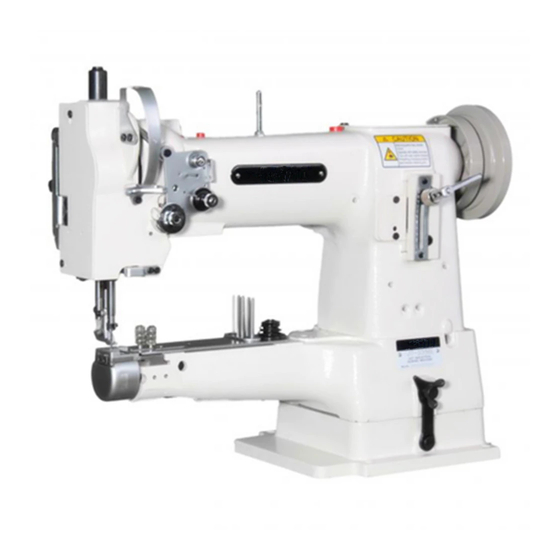
Proper use Proper use The PFAFF 335 is a single needle, free-arm sewing machine with bottom, top and needle feeds for sewing lockstitch seams. Any and all uses of this machine which have not been approved of by the manufacturer are considered to be inappropriate! The manufacturer cannot be... -
Page 10: Specifications
Specifications Specifications PFAFF 335 ◆ Stitch type:......................301 ( lockstitch) Model:............................B Needle system:......................134 - 35 Needle thickness (Nm) in 1/100 mm:................80 - 100 Max. stitch length: on sub classes -940/01-6/01 ..................4,5 mm on sub classes -2/27; -6/01; -17/01; -39/21 ..............6,0 mm on sub classes -900/52 ....................5,5 mm... -
Page 11: Disposal Of Machine
Disposal of Machine Disposal of Machine Proper disposal of the machine is the responsibility of the customer. ● The materials used for the machine are steel, aluminium, brass and various plastic ● materials. The electrical equipment comprises plastic materials and copper. The machine is to be disposed of according to the locally valid pollution control regula-ti- ●... -
Page 12: Transportation, Packing And Storage
Transportation, packing and storage Transportation, packing and storage Transportation to customer‘s premises The machines are delivered completely packed. Transportation inside the customer‘s premises The manufacturer cannot be made liable for transportation inside the customer‘s premises nor to other operating locations. It must be ensured that the machines are only transported in an upright position. -
Page 13: Explanation Of Symbols
Explanation of symbols Explanation of symbols In this instruction manual, work to be carried out or important information is accentuated by symbols. These symbols have the following meanings: Note, information Cleaning, care Lubrication Maintenance, repairs, adjustment, service work (only to be carried out by technical staff) -
Page 14: Controls
Controls Controls On/off switch The power supply to the machine is swit- ● ched on or off by turning switch 1. The illustrated on/off switch is fitted to machines with Quick motors. If other motors are used, a different switch may be fitted. -
Page 15: Lever For Lifting The Presser Foot
Controls Lever for lifting the presser foot The sewing foot can be lifted by raising ● lever 1. Fig. 7 - 03 Stitch-length adjustment lever / reverse sewing Adjust the stitch length by turning the ● milled nut on lever 1 as required. Reverse sewing For reverse sewing, push lever 1 up ●... -
Page 16: Adjustment Nut For The Top-Feed Stroke
Controls Adjustment nut for the top-feed stroke Switch the machine off! Danger due to unintentional starting of the machine! Open cover 1 on the back of the ma- ● chine, loosen screw 2 and move as re- quired. Fig. 7 - 05 Control panel (only on machines with Quick EcoDrive) The description can be found in the separate instruction manual for the control panel. -
Page 17: Installation And Commissioning
Installation and commissioning Installation and commissioning The machine must only be mounted and commissioned by qualified personnel! All relevant safety regulations are to be observed! If the machine is delivered without a table, it must be ensured that the frame and the table top which you intend to use can hold the weight of the machine and the motor. -
Page 18: Assembling The Motor (Only On Machines With Quick-Motor)
Installation and commissioning Assembling the motor .01.02 (only on machines with Quick-motor) 109-001 Fig. 8 - 02 Assemble motor mounting 1, motor 2, belt guard support 3 and belt pulley 4 as shown in ● Fig. 8-02. Tightening the V-belt .01.03 Fit the V-belt. -
Page 19: Mounting The Bottom V-Belt Guard
Installation and commissioning Mounting the bottom V-belt guard .01.04 109-07 Fig. 8 - 04 Loosen screws 2 and adjust belt guard support 1 so that the motor pulley and V-belt run ● freely. Tighten screws 2. ● Fasten belt guard 3 with screw 4. ●... -
Page 20: Fitting The Upper Belt Guard
Installation and commissioning Fitting the upper belt guard .01.05 Bei Verwendung eines großen Handrads ist die Ecke 1 des Riemenschutzteils 3 herauszu- brechen. Screw stop piece 2 onto belt guard part 3. ● Screw on belt guard part 3 onto the ●... -
Page 21: Fitting The Reel Stand
Installation and commissioning Fitting the reel stand .01.07 Fit the reel stand as shown in Fig. 8 - 07. ● Afterwards insert the stand in the hole in ● the table top and secure it with nuts pro- vided. Fig. 8 - 07 Table top mounting and circuit diagrams (see Chapter 11) -
Page 22: Connecting The Plug-In Connections And Earth Cables
Installation and commissioning Connecting the plug-in connections and earth cables .01.08 Fig. 8 - 09 Plug adapter cable 1 into control box 2. ● Remove screw 3 and tilt the machine back. ● Plug the cable coming from the machine to adapter cable 1 as marked. ●... -
Page 23: Commissioning
Installation and commissioning Insert plug 5 from the adapter cable to bush X 2. ● Connect the motor to the "motor" plug and the synchronizer to the "external" plug. ● Screw the earth cable from the sewing head and the main switch to earth point A. ●... -
Page 24: Basic Position Of The Machine Drive Unit
Installation and commissioning Basic position of the machine drive unit (only on machines with Quick-EcoDrive and control unit P40ED) Switch on the machine. ● Press the TE/speed key twice to select the input mode. ● Select parameter "798" by pressing the corresponding +/- key, and select service level ●... -
Page 25: Setting Up
Setting up Setting up All instructions and regulations in this instruction manual must be observed. Special attention must be given to all safety regulations! All setting-up work must only be done by personnel with the necessary train- ing. For all setting-up work the machine must be isolated from its power supply by turning off the on/off switch or removing the machine plug from the electric power socket! Inserting the needle... -
Page 26: Winding The Bobbin Thread, Adjusting The Thread Tension
Setting up Winding the bobbin thread, adjusting the thread tension Fig. 9 -02 Place an empty bobbin 1 onto bobbin shaft 2. ● Thread the bobbin in accordance with Fig. 9-02 and wind it anti-clockwise around bobbin ● 1 a few times. Switch on the bobbin winder while at the same time pressing bobbin winder spindle 2 ●... -
Page 27: Removing / Inserting The Bobbin Case
Setting up Removing / Inserting the bobbin case Switch the machine off! Danger due to unintentional starting of the machine! Removing the bobbin case: Lift latch 1 and take out bobbin case 2. ● Inserting the bobbin case: Insert full bobbin case 2 so that you feel ●... -
Page 28: Threading Needle Thread/Adjusting Needle Thread Tension
Setting up Threading needle thread/adjusting needle thread tension Fig. 9 - 05 Switch the machine off! Danger due to unintentional starting of the machine! Thread needle thread as shown in Fig. 9-05. ● Be sure to thread the needle from the left. ●... -
Page 29: Adjusting The Stitch Counter For The Bobbin Thread Control
Setting up Adjusting the stitch counter for the bobbin thread control (only on machines (only on machines with Quick Motor and P40 (ED) control unit) Please see the description in the separate control panel instruction manual. werden. -
Page 30: Care And Maintenance
Care and maintenance Care and maintenance Care and maintenance intervals Cleaning ............daily, in continuous operation several times General oiling ....................twice a week Oil the hook..............daily, before putting into operation Oil needle-head parts ..................twice a week Lubricate the bevel gears..................once a yea Lubricate the top-feed drive eccentric .............. -
Page 31: General Oiling
Care and maintenance General oiling Fig. 10 - 02 Switch off the machine! Danger of injury due to unintentional starting of the machine! Oil all bearing parts above the table top twice a week ( see arrows ). ● Remove screw 1 and tilt machine back- ●... -
Page 32: Oiling The Sewing Hook
Care and maintenance Oiling the sewing hook Switch off the machine! Danger of injury due to uninten- tional starting of the machine! Remove the bobbin case. ● Apply 1 - 2 drops of oil to the hook race ● daily (see arrow). Replace the bobbin case. -
Page 33: Lubricating The Bevel Gears
Care and maintenance Lubricating the bevel gears Fig. 10 - 06 Fig. 10 - 07 Switch off the machine! Danger of injury due to unintentional starting of the machine! All bevel gears must be supplied with new grease once a year. Top bevel gears Unscrew the cover on the rear side of the machine. -
Page 34: Lubricating The Top-Feed Drive Excentric
Care and maintenance Lubricating the top-feed drive excentric Switch off the machine! Danger of injury due to uninten- tional starting of the machine! Open cover 1 on the back of the machine. ● Grease nipple 2 at least once a year (use gre- ●... -
Page 35: Emptying/Cleaning The Water Bowl Of The Air Filter/Regulator
Care and maintenance Emptying/cleaning the water bowl of the air filter/regulator Switch off the machine. Disconnect the air hose at the air filter/regulating unit. Emptying the water bowl Water bowl 1 empties itself automatically ● when the air hose is disconnected from the air filter/regulator. -
Page 36: Parameter Settings
Care and maintenance Parameter settings (only on machines with Quick-EcoDrive and control unit P40ED) The selection of the user level and the alteration of parameters is described in the sepa- ● rate instruction manual for the drive unit. Parameter list .10.01 Speed for start backtack B, C... -
Page 37: Table Top Cutout
Mounting the table top Table top cutout Mounting the table top Stand position 906-3550-005/895 Drillholes for Speedcontrolunit fastening the motor (Screwed inserts M8 x 30 ) View: Controlbox P 40 ED Underside table top 91-141 940-95 Vers. 03.04.06... -
Page 38: Circuit Diagrams
Circuit diagrams Stromlaufpläne Circuit diagrams Reference list for the Circuit diagrams Control unit Quick P40 ED Control panel BDF S2 Sewing head recognition system (OTE) Sewing lamp (optional) LED stitch counter Sewing motor Main switch Manual backtacking key S1.1 Pedal speed control unit Needle position change key Single stitch key Start inhibitor (E6 stop) -
Page 39: Circuit Diagram
91-191 502-95 Circuit diagram Part 1 Version 07 .07 .06... - Page 40 Circuit diagram 91-191 502-92 Version 07 .07 .06 Part 2...
- Page 41 91-191 502-95 Circuit diagram Part 3 Version 07 .07 .06...
-
Page 42: Wearing Parts
91-000 277-25 (2x) 91-001 027-15 (2x) Subclass -940/01 91-173 664-15 91-000 452-15 (2x) Subclass -940/01 91-000 625-15 (2x) 91-000 338-15 (2x) 91-100 024-25 (2x) Subclass -940/01 PFAFF 335-G PFAFF 335 91-060 461-91 91-060 581-91 91-000 713-15 (2x) 91-000 713-15 (2x) 91-141 954-91... - Page 43 Wearing parts 99-137 151-45 91-171 049-05 91-171 042-05 95-774 464-25 91-700 996-15 PFAFF 335-900/52 91-165 505-05 91-000 094-25 (2x) 91-014 046-05 11-108 084-15 (2x) 91-000 452-15 (2x) 91-010 023-05...
- Page 44 PFAFF Industrie Maschinen AG Postfach 3020 D-67653 Kaiserslautern Königstr. 154 D-67655 Kaiserslautern Telefon: (0631) 200-0 Telefax: (0631) 17202 E-Mail: info@pfaff-industrial.com...
Need help?
Do you have a question about the 335 and is the answer not in the manual?
Questions and answers