
Related Manuals for Pfaff 3371-1 series


Summary of Contents for Pfaff 3371-1 series
-
Page 1: Instruction Manual
3371 -1/.. Instruction Manual This instruction manual applies to machines from software version 0335/013 and serial number 60 801 005 onwards 296-12-18 631/002 Betriebsanleitung engl. 08.06... - Page 2 As an alternative to the internet download the adjustment manual can also be ordered in book form under part no. 296-12-18 632/002. The reprinting, copying or translation of PFAFF Instruction Manuals, whether in whole or in part, is only permitted with our previous authorization and with written reference to the source.
-
Page 3: Table Of Contents
Index Contents ..................Page Safety ............................ 6 1.01 Directives ..........................6 General notes on safety ......................6 Safety symbols ........................7 Important points for the user ....................7 Operating and specialist personnel ..................8 .05.01 Operating personnel ......................8 .05.02 Specialist personnel ....................... 8 Danger ........................... - Page 4 Index Contents ..................Page .01.01 Adjusting the table height ....................24 .01.02 Assembling the oil pan ......................25 .01.03 Mounting the sewing head ....................26 .01.04 Mounting the spool holder ....................26 .01.05 Connecting the plug-in connections and earth cables ............27 Commissioning ........................
-
Page 5: Contents
Contents Contents ..................Chapter - Page List of parameters........................ 54 Error messages on the display..................... 61 Sewing motor errors ......................63 OTE-errors..........................63 Care and maintenance....................... 64 Maintenance intervals......................64 Cleaning the machine ......................64 Cleaning the hook compartment ..................65 Oiling the needle head parts.................... -
Page 6: Safety
Safety Safety Directives This machine is constructed in accordance with the European regulations contained in the conformity and manufacturer’s declarations. In addition to this Instruction Manual, also observe all generally accepted, statutory and other regulations and legal requirements and all valid environmental protection regulations! The regionally valid regulations of the social insurance society for occupational accidents or other supervisory organizations are to be strictly adhered to! General notes on safety... -
Page 7: Safety Symbols
It is the obligation of the user to ensure that none of the safety mechanisms are removed ● or deactivated. It is the obligation of the user to ensure that only authorized persons operate and work ● on the machine. Further information can be obtained from your PFAFF agent. -
Page 8: Operating And Specialist Personnel
Safety Operating and specialist personnel Operating personnel .05.01 Operating personnel are persons responsible for the equipping, operating and cleaning of the machine as well as for taking care of problems arising in the sewing area. The operating personnel is required to observe the following points and must: always observe the Notes on Safety in the Instruction Manual! ●... -
Page 9: Danger
Safety Danger A working area of 1 meter is to be kept free both in front of and behind the ma- chine while it is in operation so that it is always easily accessible. Never reach into the sewing area while sewing! Danger of injury by the needle! Never leave objects on the table while adjusting the machine settings! Objects can become trapped or be slung away! Danger of injury! -
Page 10: Proper Use
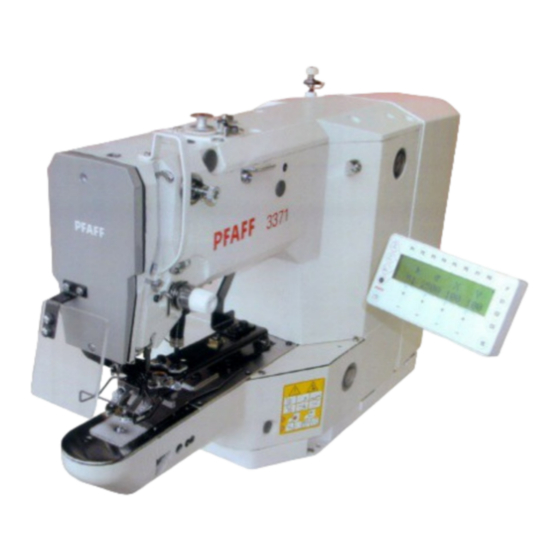
Proper use Proper use The Pfaff 3371-1/.. is an automatic sewing machine for sewing lockstitch bartacks and short seams in the sewing industry.. Any and all uses of this machine which have not been approved of by the manufacturer are considered to be inappropriate! The manufacturer cannot be... -
Page 11: Specifications
Specifications Specifications ▲ Max. sewing speed: ....................2700 spm Feed type: ......................intermittent Stitch length: ...................... 0.1 – 10.0 mm Stitch type: ......................301 (lockstitch) Needle size in 1/100 mm: for fine materials: ......................70 - 100 for medium-weight materials:..................100 - 120 for medium-heavy materials: .................. -
Page 12: Disposal Of Machine
Disposal of Machine Disposal of Machine Proper disposal of the machine is the responsibility of the customer. ● The materials used for the machine are steel, aluminium, brass and various plastic ● materials. The electrical equipment comprises plastic materials and copper. The machine is to be disposed of according to the locally valid pollution control regula-ti- ●... -
Page 13: Transportation, Packing And Storage
Transportation, packing and storage Transportation, packing and storage Transportation to customer‘s premises The machines are delivered completely packed. Transportation inside the customer‘s premises The manufacturer cannot be made liable for transportation inside the customer‘s premises nor to other operating locations. It must be ensured that the machines are only transported in an upright position. -
Page 14: Explanation Of Symbols
Explanation of symbols Explanation of symbols In this instruction manual, work to be carried out or important information is accentuated by symbols. These symbols have the following meanings: Note, information Cleaning, care Lubrication Maintenance, repairs, adjustment, service work (only to be carried out by technical staff) -
Page 15: Pedal
Control elements Control elements Main switch Switch the machine on or off by turning ● main switch 1. After switching the machine on, first press the "TE" key to bring the machine into its neutral po- sition. Fig. 7 - 01 Pedal The pedal is used to lower and raise ●... -
Page 16: Balance Wheel
Control elements Balance wheel By pressing and holding down balance ● wheel 1, it is possible to adjust the need- le bar manually. Fig. 7 - 03 Control panel The control panel is used to select seam programs, call up machine functions, change parameters, control the different operating modes, as well as for reading error signals and service settings. -
Page 17: Screen Displays
Control elements input. If the input required is invalid, e.g. because the max. permissible value for the parameter input has been reached, a double tone is audible. An SD-card reader for data transfer is integrated. Screen displays .04.01 Depending on the operating mode, on the screen 1 information is shown about the machine status, program selection, sequence program progress, input parameters, as well as error si- gnals (also see Chapter 11 Input). - Page 18 Control elements Menü This function is used in the respective operating mode to scroll within the existing menus. Wind The bobbin thread winding function is called up, see Chapter 9.03 Winding the bobbin thread. Basic position Work clamp and needle are positioned in the basic position and , if necessary, the thread trimming function is activated.
-
Page 19: Installation And Commissioning
Installation and commissioning Installation and commissioning The machine must only be installed and commissioned by qualified personnel! All relevant safety regulations must be strictly adhered to! If the machine is delivered without a table, be sure to use a stand and table top that can hold the weight of the machine with its motor. - Page 20 Installation and commissioning Removing the transit lock .01.02 Loosen nut 1. ● Remove screw 2. ● Fig. 8 - 02 Fitting the reel stand .01.03 Fit the reel stand as shown in Fig. 8 - 03. ● Afterwards insert the stand in the hole in ●...
- Page 21 Installation and commissioning Mounting the table top .01.04 (for deliveries without stand) Fig. 8 - 04 Drill holes in the table top as shown in the drawing, see Chapter 8.01.05Table top drill ● hole plans. Screw on the oil outlet 1. ●...
- Page 22 Installation and commissioning Table top drill hole plans .01.05 Top view...
- Page 23 Installation and commissioning Bottom view Drawer Gestell 906-3550-005/895 Controller Stand 906-3550-005/895...
-
Page 24: Connecting The Plug-In Connections And Earth Cables
Installation and commissioning Connecting the plug-in connections and earth cable .01.06 Fig. 8 - 05 Connect all plugs as labelled in the control box. ● Screw the earth cable from the machine and the main switch to earth point A. ●... -
Page 25: Inserting The Needle
Setting up Setting up All instructions and regulations in this instruction manual must be observed. Special attention must be given to all safety regulations! All setting-up work must only be done by personnel with the necessary training. For all setting-up work the machine must be isolated from its powe supply by turning off the on/off switch or removing the machine plug from the electric power socket! Inserting the needle... -
Page 26: Threading The Needle Thread / Adjusting The Needle Thread Tension
Setting up Threading the needle thread / adjusting the needle thread tension Fig. 9 - 02 Switch off the machine! Danger of injury if the machine is started accidentally! Thread the needle thread as shown in Fig. 9-02. ● Adjust the needle thread tension by turning milled nuts 1 and 2. ●... -
Page 27: Winding The Bobbin Thread
Setting up Winding the bobbin thread Fig. 9 - 03 Place the empty bobbin 1 on the bobbin winder spindle 2. ● Thread the thread as shown in Fig. 9-03 and wind it round bobbin 1 a few times in the ●... - Page 28 Setting up Removing / replacing the bobbin case Switch off the machine. Danger of injury if the machine starts accidentally! Removing the bobbin case Open the hook cover ● Pull out latch 1 ● Remove bobbin case 2 ● Replacing the bobbin case Push bobbin case 2 into the bobbin case ●...
-
Page 29: Selecting A Seam Program
Setting up Selecting a seam program To avoid the machine starting accidentally, to begin with the TE key must be pressed, af- ter the machine has been switched on. The machine is then in its basic position and offers a number of possibilities for selecting seam programs. - Page 30 Setting up Selecting a program station. .06.02 With the machine in its basic position, select the desired program station, e.g. P3. ● 2200 Only those program stations can be selected, which have been reserved pre- viously with a seam pattern with its respective speed and size factors, see Chapter 11.01 Reserving program stations.
-
Page 31: Adjusting The Size Of The Sewing Area
Setting up Adjusting the size of the sewing area A comparison between the sewing area size entered and the actual sewing area size of the work clamp ensures that seam pro- grams, which are not within the sewing area size, cannot be sewn. If the actual and the entered se- wing area size do not concur with each other, severe damage... -
Page 32: Setting Up The Bobbin Thread Counter
Setting up Setting up the bobbin thread counter With the machine in its basic position, select the input mode. ● With the corresponding +/- key select parameter "004". ● If required, enter the access code, see Chapter 11.04.01 Entering the access code. ●... -
Page 33: Shifting The Seam Pattern
Setting up Shifting the seam pattern To adapt the seam patterns to formed workpiece holders, selected seam patterns can be shifted. From the basic position of the machine select the desired program station, e.g. P1. ● Tact through the seam pattern, e.g. forwards. ●... -
Page 34: Inserting And Removing The Sd-Memory Card
Setting up Inserting and removing the SD-memory card Inserting the SD-memory card Open cover 1. ● Insert SD-memory card 2 into the card ● slot with the label at the front. Close cover 1 again. ● Removing the SD-memory card Open cover 1. -
Page 35: Sewing
Sewing Sewing The machine must be installed, connected and set up as described in Chapter 8 Installation and Commissioning. The machine must not be operated without the safety devices 1 to 5, see Chap- ter 1.06 Danger warnings! Danger of injury! Fig. - Page 36 Sewing Sewing in the "Sequences mode". Sequences, which have been created beforehand, can be called up with the function keys C1 to C3 (see Chap. 11.02.01 Entering sequences) Interrupting a sequence .04.01 If an interruption occurs during a sequence cycle (e.g. broken thread), it is possible to continue at the same sequence point after the error has been eliminated.
- Page 37 Input Input After the machine has been switched on, it is in the input mode. The LED in the "TE" key is illuminated. The input mode is used to reserve program stations, to enter sequences and to change machine parameters. In addition information and input possibilities for the service area are available in this mode.
-
Page 38: Entering Sequences
Input Sequences Entering sequences .02.01 The sequence program keys C1 to C3 are used to enter and select sequence programs. The sequence programs are put together from seam programs, which have been deposited un- der the station keys P1 to P8. A sequence can consist of up to 3 segments (A, B + C). - Page 39 Input 3 - 3 - 3 - 3 - 3 - 3 - 8 8 - 8 - 8 - 4 - 4 ● Press the TE key (LED is not illuminated). ● The parameters, such as number of the seam pattern, speed and size factors of the fl as- hing sequence entry are shown if the Menu key is pressed.
- Page 40 Input Parameter input After the machine has been switched on, it is in the input mode.. 2700 ● With the corresponding +/- key select the desired parameter, e.g. 003 lock seam patterns. ● With the corresponding +/- key select the desired seam pattern. ●...
- Page 41 Input Access codes The selection of seam patterns, the reservation of the program stations, the input of sequences and the selection of individual parameter levels can be locked with a 4-fi gure access code. The access code can be changed as desired. The factory set access code is "3371".
- Page 42 Input Granting access rights .04.03 ● In the input mode select the corresponding parameter ("801" to "806"), see Chapter 11.07 List of parameters. ● If required, enter the access code, see Chapter 11.04.01 Entering access codes. ● With the corresponding +/- key approve (on) or lock (OFF) access.. ●...
-
Page 43: Summary Of The Seam Patterns
Input Summary of the seam patterns Seam pattern Size of sewing area [mm] No. of stitches 16,0 x 2,0 10,0 x 2,0 16,0 x 2,5 24,0 x 3,0 10,0 x 2,0 16,0 x 2,5 10,0 x 2,0 16,0 x 2,5 24,0 x 3,0 24,0 x 3,0 6,0 x 2,5... - Page 44 Input Seam pattern Size of sewing area [mm] No. of stitches 25,0 x 2,0 25,0 x 2,0 25,0 x 0,0 25,0 x 0,0 4,0 x 20,0 4,0 x 20,0 4,0 x 20,0 4,0 x 20,0 0,0 x 20,0 0,0 x 10,0 0,0 x 20,0...
- Page 45 Input Seam pattern Size of sewing area [mm] No. of stitches 0,0 x 20,0 10,0 x 10,0 10,0 x 10,0 15,0 x 15,0 15,0 x 15,0 14,0 x 2,0 36,0 x 19,0 6,5 x 9,0 6,5 x 9,0 11,0 x 11,0 31,7 x 6,0...
-
Page 46: Program Management
Input Program Management IIn the program management the programs fi led in the machine memory or on connected SD-memory cards are displayed and can be deleted or copied. Commercially available SD-memory cards with a storage capacity of max. 512 MB can be inserted in the control panel. -
Page 47: Display Of The Data In The Machine Memory
Input Display of the data in the machine memory .06.02 ● Call up the program management, see Chapter 11.06.01 Calling up the program management. ● Press the left +/- keys until the corresponding menu item appears. ● Confi rm the selection of the menu item with the "Enter" function by pressing the right plus key. -
Page 48: Display Of The Data On The Sd-Memory Card
Input Display of the data on the SD-memory card .06.03 ● Call up the program management, see Chapter 11.06.01 Calling up the program management. ● Press the left +/- keys until the corresponding menu item appears. ● Confi rm the selection of the menu item with the "Enter" function by pressing the right plus key. -
Page 49: Copying Data Onto The Sd-Memory Card
Input Copying data onto the SD-memory card .06.04 ● Call up the program management, see Chapter 11.06.01 Calling up the program management. COPY ● Press the left +/- keys until the corresponding menu item appears. ● Confi rm the selection of the menu item with the "Enter" function by pressing the right plus key. -
Page 50: Copying Data Into The Machine Memory
Input Copying data into the machine memory .06.05 ● Call up the program management, see Chapter 11.06.01 Calling up the program management. COPY ● Press the left +/- keys until the corresponding menu item appears. ● Confi rm the selection of the menu item with the "Enter" function by pressing the right plus key. -
Page 51: Deleting Data In The Machine Memory
Input Deleting data in the machine memory .06.06 ● Call up the program management, see Chapter 11.06.01 Calling up the program management. ● Press the left +/- keys until the corresponding menu item appears. ● Confi rm the selection of the menu item with the "Enter" function by pressing the right plus key. -
Page 52: Deleting Data From The Sd-Memory Card
Input Deleting data from the SD-memory card .06.07 ● Call up the program management, see Chapter 11.06.01 Calling up the program management. ● Press the left +/- keys until the corresponding menu item appears. ● Confi rm the selection of the menu item with the "Enter" function by pressing the right plus key. -
Page 53: Formatting The Sd-Memory Card
Input Formatting the SD-memory card .07 .08 ● Call up the program management, see Chapter 11.07.01 Calling up the program management. FORMAT ● Press the left +/- keys until the corresponding menu item appears. ● The formatting process is started with the "Enter" function by pressing the right plus key. -
Page 54: List Of Parameters
Input List of parameters The parameter setting values my only be altered by appropriately trained staff! Group Parameter Description Setting Set value Gruppe Parameter Bedeutung range Maximum speed 500 - 2700 2700 This parameter is used to fi x the max. sewing speed (upper limit). - Page 55 Input Group Parameter Description Setting Set value Gruppe Parameter Bedeutung range Reversing after thread trimming ON - OFF Reverse position [°] 0 - 14 With this parameter it is possible to switch the automatic reversing func- tion after thread trimming on or off. If the reversing function is switched on, the reverse position can be set by tur- ning the balance wheel.
- Page 56 Input Group Parameter Description Setting Set value Gruppe Parameter Bedeutung range NIS "needle in material" [°] 65 -166 This parameter is used to set the NIS signal. If the function is executed, the position can be entered by turning the balance wheel.
- Page 57 Input Group Parameter Description Setting Set value Gruppe Parameter Bedeutung range Thread take-up lever t.d.c. [°] 45 - 53 The position for the t.d.c. thread take- up lever is entered here. If the func- tion is executed, the position can be set by turning the balance wheel.
- Page 58 Input Group Parameter Description Setting Set value Gruppe Parameter Bedeutung range Display inputs With this function the digital inputs can be checked. "IN" shows the input numbers (1 - 16). Under "VAL" the re- spective switch status is displayed. IN1, programmable input 1 IN2, programmable input 2...
- Page 59 Input Group Parameter Description Setting Set value Gruppe Parameter Bedeutung range Connect outputs With this function the outlets can be connected. "OUT" shows the outlet selected (1-16). Under "VAL" the selected output is set (S) with the plus/minus key (+), and reset (R) with the plus/minus key.
- Page 60 Input Group Parameter Description Setting Set value Gruppe Parameter Bedeutung range Thread trimming sequence The sequence for a complete thread trimming cycle is started with the +/- key (+) below CUT and below THR. Cold start (RESET) With this function the control unit carries out a cold start (RESET) with which the data is reset.
-
Page 61: Error Messages On The Display
Input Group Parameter Description Setting Set value Gruppe Parameter Bedeutung range Automatic clamp opening off ON - OFF With this function the automatic ope- ning of the clamp after thread trim- ming can be switched off. After the machine has been switched off, the automatic clamp opening function is always activated. - Page 62 Input ERROR: 5 Processor error ILLEGAL_WORD_OPERAND ERROR: 6 Processor error ILLEGAL_INSTRUCTION ERROR: 7 Processor error ILLEGAL_BUS_ACCESS ERROR: 8 Processor error NMI ERROR: 10 OTE (Sewing head recognition unit) not attached ERROR: 11 OTE not programmed (new) ERROR: 12 OTE check sum error ERROR: 13 OTE header invalid ERROR: 14...
-
Page 63: Sewing Motor Errors
Input ERROR: 409 Zero point not found ERROR: 416 Error in SD-memory card reader 1: No SD-memory card inserted 2: Wrong SD-memory card (does not match the machine) 3: SD-memory card not inserted correctly 4: SD-memory card with write protection 5: Data error on SD-memory card 6: Formatting failed 7: File does not match machine... -
Page 64: Care And Maintenance
Care and maintenance Care and maintenance Maintenance intervals Clean the entire machine ................. once a week Clean the hook compartment ..once a day, more often when in continuous operation Oiling the needle head parts ................as required Oiling the hook....................as required Oiling the bearing points in the arm..............once a month During all cleaning work the machine must be disconnected from the power supply by switching off the main switch or pulling out the plug! -
Page 65: Cleaning The Hook Compartment
2. Only use oil with a mean viscosity of 10.0 mm /s at 40°C and a density of 0.847 g/cm 15°C. We recommend PFAFF sewing machine oil, part no. 280-1-120 105. Fig. 12 - 02... -
Page 66: Oiling The Hook
Fig. 12-04. Only use oil with a mean viscosity of 10.0 mm /s at 40°C and a density of 0.847 g/cm at 15°C. We recommend PFAFF sewing machine oil, part no. 280-1-120 105. -
Page 67: Oiling The Bearing Points In The Arm
Only use oil with a mean viscosity of 10.0 mm /s at 40°C and a density of 0.847 g/cm 15°C. We recommend PFAFF sewing machine oil, part no. 280-1-120 105. Fig. 12 - 05 Oil disposal When required, unscrew oil collector 1 ●... -
Page 68: Circuit Diagrams
Circuit diagrams Stromlaufpläne Circuit diagrams Circuit diagram reference list Controller Quick P 320MS Control panel S3A Sewing head recognition system (OTE) Hybrid light barrier Y axis Hybrid light barrier X axis Hybrid light barrier clamp monitoring Sewing lamp Sewing motor Sewing motor Y axis Sewing motor X axis Main switch... - Page 69 91-191 506-95 Circuit diagrams Version 07 .07 .06 Page 1...
- Page 70 Circuit diagrams 91-191 506-95 Version 07 .07 .06 Page 2...
- Page 71 91-191 506-95 Circuit diagrams Version 07 .07 .06 Page 3...
- Page 72 Circuit diagrams 91-191 506-95 Version 07 .07 .06 Page 4...
-
Page 73: Wearing Parts
A detailed parts list for the complete machine is included with the accesso- ries. In case of loss the parts list can be downloaded from the internet address www.pfaff-industrial.de/pfaff/de/service/downloads As an alternative to the internet download the parts lists can also be ordered in book form under part no. - Page 74 PFAFF Industrie Maschinen AG Postfach 3020 D-67653 Kaiserslautern Königstr. 154 D-67655 Kaiserslautern Telefon: (0631) 200-0 Telefax: (0631) 17202 E-Mail: info@pfaff-industrial.com...
Need help?
Do you have a question about the 3371-1 series and is the answer not in the manual?
Questions and answers