Table of Contents
Advertisement
Quick Links
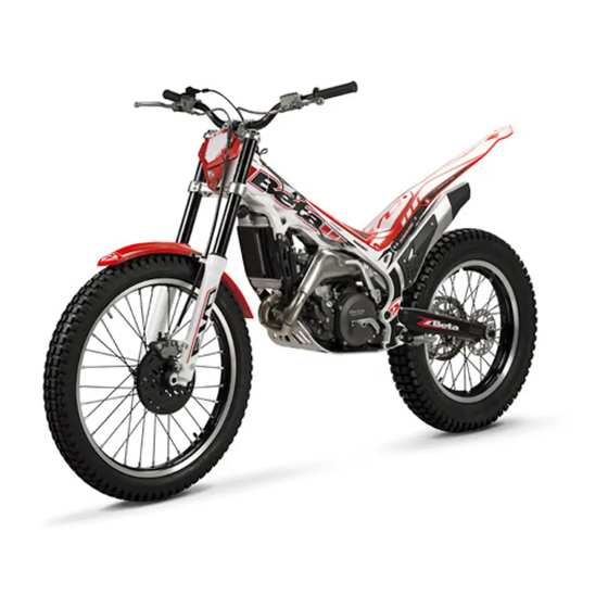
EVO 2T
Thanks for you preference, and have a good time! This hand-
book contains the information you need to properly operate and
maintain your motorcycle.
The data, specifications and images shown in this manual does not constitute
an engagement on the part of BETAMOTOR S.p.A. BETAMOTOR reserves
the right to make any changes and improvements to its models at any mo-
ment and without notice.
Code 007440240 000
GB
1
Advertisement
Chapters
Table of Contents

Related Manuals for Beta EVO 2T


Summary of Contents for Beta EVO 2T
- Page 1 EVO 2T Thanks for you preference, and have a good time! This hand- book contains the information you need to properly operate and maintain your motorcycle. The data, specifications and images shown in this manual does not constitute an engagement on the part of BETAMOTOR S.p.A. BETAMOTOR reserves the right to make any changes and improvements to its models at any mo- ment and without notice.
- Page 2 IMPORTANT We recommend you to check all the tightenings after the first one or two hours’ ride over rough ground. Special attention should be paid to the following parts: • rear sprocket • ensure that the footrests are properly fixed •...
-
Page 3: Table Of Contents
TABLE OF CONTENTS Operating instructions ................5 Symbols ....................5 Riding safety ..................6 CHAPTER 1 GENERAL INFORMATION ..........7 Vehicle identification data ............... 8 Familiarizing with the vehicle..............9 Specifications ..................10 Electrical system ................... 14 Recommended lubricants and liquids ............18 CHAPTER 2 OPERATION .............. - Page 4 Clutch control ..................47 Check of steering gear................49 Oil fork ....................50 Tyres....................54 Chain ....................55 Headlight .................... 57 Rear tail light ..................58 Cleaning the vehicle ................59 Prolonged inactivity ................60 Scheduled maintenance vehicle ............61 Tightening torque overview ..............
-
Page 5: Operating Instructions
OPERATING INSTRUCTIONS • The vehicle must be accompanied by: number-plate, registration document, tax disc and insurance. • Changes to the engine or other parts is punishable by law with severe penalties, including the confiscation of the vehicle. • Do not sit on the vehicle stand. •... -
Page 6: Riding Safety
RIDING SAFETY • Observe the Highway Code. • Always wear approved personal safety equipment. • Always ride with the low beam on. • Always keep the crash helmet visor clean. • Avoid wearing garments with hanging ends. • Do not keep sharp or brittle objects in your pockets while riding. •... -
Page 7: Chapter 1 General Information
CHAPTER 1 GENERAL INFORMATION CONTENTS Vehicle identification data ............... 8 Frame identification ................8 Engine identification ................8 Familiarizing with the vehicle..............9 Main parts ..................9 Specifications ..................10 Weight ................... 10 Vehicle dimensions ................10 Tyres ....................10 Capacities .................. -
Page 8: Vehicle Identification Data
VEHICLE IDENTIFICATION DATA FRAME IDENTIFICATION Frame identification data A are stamped on the right side of the steering head tube. ENGINE IDENTIFICATION Engine identification data B are stamped in the area shown in the picture. WARNING: Tampering with the identification numbers is severely punished by law. -
Page 9: Familiarizing With The Vehicle
FAMILIARIZING WITH THE VEHICLE MAIN PARTS 1 Fuel tank 11 Engine 2 Tank cap 12 Front mudguard 3 Silencer 13 Rear mudguard 4 Rear shock absorber 14 Kick-start 5 Headlight 15 Gear lever 6 Rear light 16 Rear brake lever 7 Side stand 17 Front brake lever 8 Fork... -
Page 10: Specifications
SPECIFICATIONS WEIGHT Version EVO 125 EVO 200 EVO 250 EVO 300 Dry weight [kg] 67.5 68.5 68.5 68.5 Front [kg] 33.75 34.25 34.25 34.25 Rear [kg] 33.75 34.25 34.25 34.25 VEHICLE DIMENSIONS maximum length ............... 1990 mm maximum width ................850 mm wheelbase ................ -
Page 11: Front Suspension
FRONT SUSPENSION Version EVO 125 EVO 200 EVO 250 EVO 300 Wheel excursion [mm] right left right left right left right left fork leg fork leg fork leg fork leg fork leg fork leg fork leg fork leg K spring 7.65 7.65 7.65... -
Page 12: Engine
ENGINE Version EVO 125 EVO 200 EVO 250 EVO 300 Single-cylin- Single-cylin- Single-cylin- Single-cylin- Type der, 2-stroke der, 2-stroke der, 2-stroke der, 2-stroke Bore x stroke 54 x 54 64 x 60.5 72.5 x 60,5 79 x 60.5 Displacement [cm 123.6 194.6 249.7... -
Page 13: Gear Box
GEAR BOX Version EVO 125 EVO 200 EVO 250 EVO 300 Primary drive 20/71 20/71 22/69 22/69 Gear ratio 12/34 12/34 12/34 12/34 1st gear Gear ratio 14/32 14/32 14/32 14/32 2nd gear Gear ratio 15/29 15/29 15/29 15/29 3rd gear Gear ratio 18/27 18/27... -
Page 14: Electrical System
ELECTRICAL SYSTEM ELECTRICAL DIAGRAM HOMOLOGATED VERSION Key to colours Bi = White Ve = Green Ma = Brown Vi = Purple Bl = Blue Ne = Black Gi = Yellow Rs = Red Ar = Orange Az = Sky-blue Ro = Pink Gr = Grey... -
Page 15: Legend Electrical Diagram Homologated Version
LEGEND ELECTRICAL DIAGRAM HOMOLOGATED VERSION R.H. front turn signal with bulb 12V - 10W Headlamp (double filament bulb) 12V-35/35W Position light with bulb 12V - 5W High beam indicator light with bulb 12V 12W Dashboard indicator light with bulb 12V 1,3W Turn signal indicator light with bulb 12V 1,3W L.H. -
Page 16: Electrical Diagram Race Version
ELECTRICAL DIAGRAM RACE VERSION Key to colours Bi = White Ve = Green Ma = Brown Vi = Purple Bl = Blue Ne = Black Gi = Yellow Rs = Red Ar = Orange Az = Sky-blue Ro = Pink Gr = Grey... -
Page 17: Legend Electrical Diagram Race Version
LEGEND ELECTRICAL DIAGRAM RACE VERSION Headlamp (double filament bulb) 12V-35/35W Horn 12V Horn button Engine stop button Switch for change mapping (yellow) Light switch (black) Tail light with bulb 12V - 3W Generator Pick-up 10) H.T. coil 11) Electronic control unit 12) Regulator 12V 13) Thermal switch 14) Electrofan... -
Page 18: Recommended Lubricants And Liquids
RECOMMENDED LUBRICANTS AND LIQUIDS For better operation and longer vehicle life, we advise you to use the products listed in the following chart: PRODUCT TYPE SPECIFICATIONS OILMIXTURE LIQUI MOLY RACING SYNTH 2T GEAR AND CLUTCH OIL LIQUI MOLY RACING 4T 10W-30 BRAKE OIL LIQUI MOLY BRAKE FLUID DOT4 CLUTCH ACTUATOR OIL... -
Page 19: Chapter 2 Operation
CHAPTER 2 OPERATION CONTENTS Main parts ..................20 Fuel valve ..................20 Starter .................... 20 Clutch lever ..................21 LH switch ..................21 RH switch ..................21 Front brake lever and gas control ............22 Gearchange lever................22 Brake pedal ..................22 Kick-start .................. -
Page 20: Main Parts
MAIN PARTS FUEL VALVE Fuel valve has three positions: OFF: fuel supply closed. Fuel cannot pass from the tank to the carburettor. ON: fuel supply enabled. Fuel flows from the tank to the carburettor. The tank empties until it reaches the reserve level. RES: reserve fuel supply. -
Page 21: Clutch Lever
CLUTCH LEVER Clutch lever 1 is fitted to the left-hand side of the handlebars. Screw A can be used to alter the home position of the lever (see Adjustments). LH SWITCH The off switch is positioned on the left-hand side of the handlebar and consists of the following: shutdowns engine : it is necessary to... -
Page 22: Front Brake Lever And Gas Control
FRONT BRAKE LEVER AND GAS CONTROL The front brake lever 1 and the gas throt- tle 2 are located on the right side of the handlebar. GEARCHANGE LEVER Gearchange lever is fitted to the left side of the engine. The positions corresponding to the different gears are shown in the figure. - Page 23 SIDE STAND Press down side stand with the foot and lean the vehicle against it. Ensure that the ground is solid and the vehicle stands steadily. WARNING! The kickstand has an automatic closing device. When the vehicle weight on the kickstand is reduced, it closes automatically.
-
Page 24: Checks Before And After Use
CHECKS BEFORE AND AFTER USE For safe driving and long vehicle life you should: • Check all fluid levels. • Check the correct operation of the brakes and brake pad wear (page 44). • Check pressure, general condition and thickness of tread (page 10). • Check that the spokes are properly tightened. • Check the chain tension (page 55). • Check the adjustment and the operation of all the cable controls. • Inspect all the nuts and bolts. • With the engine running, check the operation of the headlight, the rear and brake lights, the indicators, the warning lights and the horn. • Wash the motorcycle thoroughly after off-road use (page 59). BREAKING IN The breaking-in period lasts approximately 5 hours, during which it is advisable to: • Avoid travelling at constant speed. -
Page 25: Fuelling
FUELLING Use a blend of high-octane unleaded gasoline and synthetic oil at 1,5%. Fuel tank capacity is shown on page 10. To open the fuel tank’s cap, turn it anti- clockwise. To close the fuel tank’s cap, set it on the tank and crew it clockwise. For the type of oil mixture refer to the “Rec- ommended fluids and lubricants”... -
Page 26: Startup
STARTUP Set the fuel tank tap to ON or RES (see page 20). - Check that the gears are in neutral (page 22). - Pull the clutch lever (page 21). KICKSTART (page 22): depress the kick-starter with a sharp move- ment of the foot ATTENTION Once the pedal has been de-... -
Page 27: Chapter 3 Adjustments
CHAPTER 3 ADJUSTMENTS CONTENTS Key to symbols..................28 Brakes ....................28 Front brake ..................28 Rear Brake..................28 Clutch ....................29 Adjustment of gas clearance ..............29 Accelerator ..................30 Adjusting the idle speed ..............30 Handlebar adjustment ................30 Adjusting fork .................. -
Page 28: Key To Symbols
KEY TO SYMBOLS Tightening torque Threadlocker Medium Grease BRAKES FRONT BRAKE The front brake is disk type with hydraulic control. The position of the lever is controlled through the use of register 1. Once the position of the lever has been changed, register 2 must be changed to restore the initial correct clearance. -
Page 29: Clutch
CLUTCH The position of the lever is controlled through the use of register 1. Once the position of the lever has been changed, register 2 must be changed to restore the initial correct clearance. The idle stroke of push rod must not be less than 0.9 mm 0,9 mm ATTENTION: reduced clearance... -
Page 30: Accelerator
ACCELERATOR ADJUSTING THE IDLE SPEED In order to perform this operation correctly, we advise you to do it when the engine is hot, connecting an electric revolution counter to the spark plug wire. Then use a screwdriver on register screw A to cali- brate the minimum with 900÷1000 rpm. -
Page 31: Shock Absorber
ADJUSTING THE SPRING PRELOAD Spring preload is adjusted by means of screw 2. Turning clockwise will increase the preload, while rotating counter- clock- wise decreases the preload. For standard calibration, refer to page SHOCK ABSORBER ADJUSTING THE REBOUND DAMPER The hydraulic brake unit in extension deter- mines the behaviour in the extension phase of the shock absorber and can be adjusted using screw 1. -
Page 32: Suspension Adjustment According To The Motorcyclist's Weight
ADJUSTING THE SPRING PRELOAD To adjust the spring preload, use the pro- cedure described below. Loosen counter-ring 1, rotate ring 2 clock- wise to increase the spring preload (and consequently the shock absorber preload) or anticlockwise to decrease it. After obtaining the desired preload, turn counter-ring 1 until it stops against adjust- ing ring 2. -
Page 33: Chapter 4 Checks And Maintenance
CHAPTER 4 CHECKS AND MAINTENANCE CONTENTS Key to symbols..................34 Gear oil ....................34 Check the level ................34 Replacement ................... 34 Coolant ....................35 Check the level ................35 Replacement ................... 36 Radiator grill ................... 37 Air filter ....................37 Removing and fitting air filter ............ -
Page 34: Key To Symbols
KEY TO SYMBOLS Tightening torque Threadlocker Medium Grease GEAR OIL CHECK THE LEVEL Keep the vehicle in vertical position relative to the ground. When engine is cold check the oil level by means of porthole 1. The oil level must be always visible from the porthole. -
Page 35: Coolant
COOLANT CHECK THE LEVEL Keep the vehicle in vertical position relative to the ground. The level of the coolant must be checked when the engine is cold. Use the following procedure: - Unscrew cap 1 and ensure that the liq- uid is visible in the lower portion of the loading tube. -
Page 36: Replacement
REPLACEMENT Position the vehicle on a flat base and in a stable manner. Replacement of the coolant must take place when the engine is cold. 1) Unscrew cap 1. 2) Place a container under screw 2. 3) Unscrew the screw 2. 4) Drain the liquid. -
Page 37: Air Filter
- with the eyes, rinse immediately with plenty of water and seek medical advice; - with skin, Immediately clean contaminat- ed areas with soap and water Change clothing that is contaminated with cool- ant. If coolant is swallowed, contact a doctor immediately. -
Page 38: Cleaning Air Filter
- Remove the filter frame and the filter by unscrewing the screw 2. WARNING: After every intervention, check that nothing has been left inside the filter box. - Reassemble by performing the operations in reverse order. CLEANING AIR FILTER - Thoroughly wash the filter with water and soap. -
Page 39: Spark Plug
Verify the integrity of water proofing gaskets on air box shown in the picture. Change them if these are damaged. To replace, contact authorised Betamotor customer service. WARNING: Never use the vehicle if the air filter is not in place. The infiltration of dust and dirt can cause damage and considerable wear. -
Page 40: Carburetor
CARBURETOR DRAINING THE CARBURETOR FLOAT CHAMBER If the carburetor tank needs to be emptied, proceed as described. Perform the opera- tion once the engine is cold. Turn the fuel cock to OFF position (see page 20). Place a cloth under the carburettor in order to collect the fuel that comes out. -
Page 41: Float Level Check
Fuel must not come into contact with the skin, eyes, and clothing. Do not breathe in the fuel vapours. If contact occurs with the eyes, rinse immediately with plenty of water and seek medical advice. If contact occurs with skin, immediately clean contaminated areas with soap and water If fuel is swallowed, contact a doctor im- mediately. -
Page 42: Front Brake
FRONT BRAKE CHECK THE LEVEL OF THE FRONT BRAKE FLUID Check the level of the brake fluid through sight A. The level of the fluid should never fall below the mark in the sight. RESTORING THE LEVEL OF THE FRONT BRAKE FLUID To restore the level of the brake fluid, loosen the two screws 1, lift cap 2 and add brake fluid until its level is 5 mm below the upper... -
Page 43: Bleeding The Front Brake
BLEEDING THE FRONT BRAKE To bleed air from the front brake circuit, proceed as follows: •Remove the rubber cap 1 from the valve •Open the sump cap. •Insert one end of a transparent tube into a container. •Pump with the brake lever 2/3 times and keep the lever pressed. -
Page 44: Rear Brake
FRONT BRAKE LINING CONTROL 2 mm In order to verify the wear condition of front brake is enough to view the caliper from the bottom, where is possible to glimpse the brake lining tails which will have to show a brake of 2 mm in thickness. If the stratum is lesser let’s start replacing them. -
Page 45: Bleeding The Rear Brake
WARNING: The brake fluid is extremely corro- sive. Take care not to spill it on the paintwork. Wear appropriate protective cloth- ing and protection gloves. Keep coolant out of reach of chil- dren. WARNING: Avoid any direct con- tact of the liquid with skin, eyes or clothing. -
Page 46: Rear Brake Lining Control
NOTE: During this procedure, continuously top up the brake pump thank to replace the oil that is out flowing. •Remove the tube. •Replace the rubber cap. Close the oil reservoir cap. Use the liquid indicated on page 18 in the “Recommended lubricants and liquids” table. -
Page 47: Clutch Control
CLUTCH CONTROL CHECK OIL LEVEL To check the oil level in the clutch pump, first remove cover 1. Remove the two screws 2 and take off cover 1 together with the rubber bellows. With the clutch pump in a horizontal posi- tion, the level of the oil should be 5 mm below the upper rim. -
Page 48: Bleeding Clutch Control
BLEEDING CLUTCH CONTROL • Remove the rubber cap 1 from the valve 2. • Open the sump cap. • Insert one end of a trasparent tube into a container. • Pump with the brake lever 2/3 times and keep the lever pressed. •... -
Page 49: Check Of Steering Gear
CHECK OF STEERING GEAR Periodically check the play in the steering sleeve by moving the fork back and forth as shown in the figure. Whenever you feel play, adjust as described below: Loosen the screws 1. 10Nm Loosen the screw 2. Take up the play by means of nut 3. -
Page 50: Oil Fork
OIL FORK The procedure for changing the oil in the forks is provided only for information. We recommend having the operation performed by a BETAMOTOR authorized workshop. REMOVING LEGS To replace, proceed as follows: Position the vehicle on the central bike stand. -
Page 51: Oil Replacement Left Leg
Empty the fork leg and the cartridge, drain- ing all the oil inside. Reassemble the cartridge on the fork leg tightening the fixing screw, then refill oil in the cartridge. Pour in the quantity of liquid indicated on page 11. Use the liquid indicated on page 18 in the “Recommended lubricants and liquids”... -
Page 52: Legs Assembly And Parts
LEGS ASSEMBLY AND PARTS Apply the legs to the vehicle and tighten the screws 1 to the torque indicated. ATTENTION: Tightening of the screws should be carried out by adjusting the torque wrench to to the stability torque with 10Nm repeated tightening until stability torque has been achieved. -
Page 53: Linkage Rear Suspension
NOTE: It is recommended not to wash with water jets at high pressure in the zone of the linkage. Perform the check according to the times indicated in the table on page 61. To verify device, contact authorised Beta- motor customer service. -
Page 54: Tyres
TYRES Only fit tyres approved by BETAMOTOR. Unsuitable tyres can adversely affect the road holding of the vehicle. • To protect your safety, immediately replace any damaged tyres. • Slick tyres adversely affect the road holding of the vehicle, especially on wet roads and in off-road riding. -
Page 55: Chain
CHAIN Checking the drive chain periodically to ensure longer chain life. Always keep it lubricated and clean of deposited dirt. Take special care in preventing the lubri- cant from coming into contact with the rear tyre or brake disc, otherwise the tyre grip and the action of the brake would be greatly reduced, making it very difficult to control the vehicle. - Page 56 Rotate register 3 into the same position as register 2. Ensure the distance between chain and swingarm is that recommended. If the distance between chain and swingarm is not that recommended pro- ceed to readjustment. Tighten the pin to the torque indicated. 80Nm...
-
Page 57: Headlight
HEADLIGHT Keep the headlight glass clean at all times (page 59). REPLACING THE HEADLIGHT BULBS Dismantle the headlight mask removing the two retaining screws 1 indicated in the figure. Remove the screws 2 indicated in the figure. 0,5Nm Take out the bulb assembly from the bulb holder. -
Page 58: Rear Tail Light
REAR TAIL LIGHT Keep the tail light glass clean at all times (see page 59). Remove the screws indicated in the figure. 0,5Nm Remove the bulb holder from its place. Remove the bulb. To reassemble, proceed inversely as de- scribed above. -
Page 59: Cleaning The Vehicle
CLEANING THE VEHICLE GENERAL PRECAUTIONS WARNING: Do not clean your vehicle with a high-pressure device with a strong jet of water. Excessive pressure can reach electrical components, con- nectors, flexible cables, bearings, etc and can damage or destroy them. WARNING: Wash motorbikes frequently with cold water that are used near the sea (salty air) and on roads subject to salt spreading in winter. -
Page 60: Prolonged Inactivity
To prevent malfunction of the electrical system, treat electric contacts and switches with electrical contact spray. ATTENTION: any oxidation of electrical contacts may result in serious malfunc- tioning. PROLONGED INACTIVITY A few simple operations should be performed to keep the vehicle in good condition whenever it is to remain inactive for a long period (e.g. -
Page 61: Scheduled Maintenance Vehicle
SCHEDULED MAINTENANCE VEHICLE Engine Spark plug Clutch Reed valve Cylinder Piston sealing rings Piston Water pump fan Shim water pump fan Gear water pump fan Water pump shaft Water pump shaft sealing Coolant Gear oil Connecting rod Crankshaft bearings Gear Vehicle Rear shock absorber Linkage rear suspension... -
Page 62: Tightening Torque Overview
TIGHTENING TORQUE OVERVIEW Here below is an overview of the tightening torque of all pieces subject to adjust- ment or maintenance: Forecarriage Tightening torque [Nm] Threadlock Wheel pin Fork foots - wheel pin Brake caliper - Fork Steering head base - fork legs Steering head - fork legs Stem pin on steering head Upper handlebar u-bolt... - Page 63 Headlamps Tightening torque [Nm] Threadlock Headlight mask Headlight bulb socket Tail light glass Medium strength threadlock WARNING: Tightening of the screws should be carried out by adjusting the torque wrench to the stability torque with repeated tightening until stability torque has been achieved.
- Page 65 CHAPTER 5 TROUBLESHOOTING CONTENTS Troubleshooting ................... 66 Alphabetical index ................67...
-
Page 66: Chapter 5 Troubleshooting
TROUBLESHOOTING PROBLEM CAUSE REMEDY The engine turns over but Fuel valve in OFF position Move the fuel valve in ON or RES will not start position Dirty carburettor jets Contact authorised Betamotor cus- tomer service Spark plug dirty Clean or replace the spark plug Spark gap wrongly adjusted Restore the spark gap (page 39) Fault in the ignition system... - Page 67 ALPHABETICAL INDEX Accelerator ..................30 Adjusting fork ..................30 Adjustment of gas clearance ..............29 Air filter ....................37 Brakes ....................28 Breaking in..................24 Carburetor ..................40 Chain ....................55 Check of steering gear................49 Checks before and after use ..............24 Cleaning the vehicle ................
- Page 68 Rear brake ..................44 Rear tail light ..................58 Recommended lubricants and liquids ............18 Riding safety ..................6 Scheduled maintenance vehicle ............61 Shock absorber..................31 Spark plug ..................39 Specifications ..................10 Startup ....................26 Suspension adjustment according to the motorcyclist’s weight ....32 Symbols ....................
Need help?
Do you have a question about the EVO 2T and is the answer not in the manual?
Questions and answers