Table of Contents
Advertisement
125 - 200 - 250 - 290cc - 2009
125 - 200 - 250 - 290cc - 2009
125 - 200 - 250 - 290cc - 2009
125 - 200 - 250 - 290cc - 2009
125 - 200 - 250 - 290cc - 2009
EVO 2T
EVO 2T
EVO 2T
EVO 2T
EVO 2T
MANUALE D'ISTRUZIONI
MANUALE D'ISTRUZIONI
MANUALE D'ISTRUZIONI
MANUALE D'ISTRUZIONI
MANUALE D'ISTRUZIONI
INSTRUCTION MANUAL
INSTRUCTION MANUAL
INSTRUCTION MANUAL
INSTRUCTION MANUAL
INSTRUCTION MANUAL
MANUAL DE ISTRUCCIONES
MANUAL DE ISTRUCCIONES
MANUAL DE ISTRUCCIONES
MANUAL DE ISTRUCCIONES
MANUAL DE ISTRUCCIONES
MANUEL D'INSTRUCTIONS
MANUEL D'INSTRUCTIONS
MANUEL D'INSTRUCTIONS
MANUEL D'INSTRUCTIONS
MANUEL D'INSTRUCTIONS
Advertisement
Table of Contents

Related Manuals for Beta EVO 2T


Summary of Contents for Beta EVO 2T
- Page 1 EVO 2T EVO 2T EVO 2T EVO 2T EVO 2T 125 - 200 - 250 - 290cc - 2009 125 - 200 - 250 - 290cc - 2009 125 - 200 - 250 - 290cc - 2009 125 - 200 - 250 - 290cc - 2009 125 - 200 - 250 - 290cc - 2009 MANUALE D’ISTRUZIONI...
- Page 2 Thank you for choosing BETA. Wishing you a lots of good biking! This manual wiIl give you the information you need to use your motorcycle correctly and to keep it in excellent condition. BETAMOTOR S.p.A. reserves the right to change the data and features described in...
- Page 3 A A A A A TTENTION TTENTION TTENTION TTENTION TTENTION After the first training hour, check all the tightenings and in a particular manner: • Footboard supports • Front and rear brake disks • Wheel rims • Shock absorber bolt •...
-
Page 4: Table Of Contents
SECTION 1: GENERAL INFORMA SECTION 1: GENERAL INFORMA TION TION SECTION 1: GENERAL INFORMA SECTION 1: GENERAL INFORMA SECTION 1: GENERAL INFORMATION TION TION Main parts ..................... 44 Vehicle identification data................44 Instrument panel and controls................44 Technical data ......................45 Electrical diagram .................... -
Page 6: Main Parts
INDEX INDEX INDEX INDEX INDEX Main parts Vehicle identification data Instrument panel and controls Technical data Electrical diagram... -
Page 7: Instrument Panel And Controls
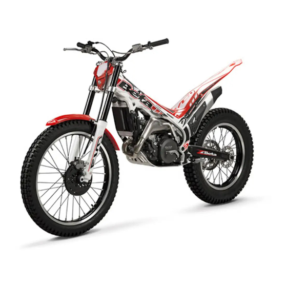
MAIN P MAIN P MAIN PAR MAIN P MAIN P ARTS TS TS TS TS 1- 1- 1- 1- 1-Filter box 2 2 2 2 2-Fuel tank 3- 3- 3- 3- 3-Fuel cap 4- 4- 4- 4- 4-Silencer 5- 5- 5- 5- 5-Kick starter VEHICLE IDENTIFICA VEHICLE IDENTIFICA TION D... -
Page 9: Electrical Diagram
ELECTRICAL DIA ELECTRICAL DIA GRAM GRAM ELECTRICAL DIA ELECTRICAL DIA GRAM ELECTRICAL DIA GRAM GRAM... - Page 10 INDEX INDEX INDEX INDEX INDEX Check and maintenance before and after off-road use Fueling Recommended lubricants and liquids Breaking in Start up...
-
Page 11: Fueling
CHECKS AND MAINTENANCE BEFORE AND AFTER OFF CHECKS AND MAINTENANCE BEFORE AND AFTER OFF CHECKS AND MAINTENANCE BEFORE AND AFTER OFF-RO -ROAD USE AD USE AD USE AD USE CHECKS AND MAINTENANCE BEFORE AND AFTER OFF CHECKS AND MAINTENANCE BEFORE AND AFTER OFF AD USE In order to avoid problems connected to the operation of the vehicle, it is advisable to perform some checking and maintenance operations before and after use. -
Page 12: Recommended Lubricants And Liquids
RECOMMENDED LUBRICANTS AND LIQUIDS RECOMMENDED LUBRICANTS AND LIQUIDS RECOMMENDED LUBRICANTS AND LIQUIDS RECOMMENDED LUBRICANTS AND LIQUIDS RECOMMENDED LUBRICANTS AND LIQUIDS For better operation and longer vehicle life, we advise you to use the products listed in the following chart: M " "... -
Page 13: Startup
ST ST STAR ARTUP •Open fuel tank valve B B B B B OFF = closed ON = open RES = reserve •Check that the gears are in neutral •Depress the kick-starter with a sharp movement of the foot and slightly turn the gas control •Always close the fuel tank valve when the engine is off. - Page 14 INDEX INDEX INDEX INDEX INDEX Gearbox oil Brake pump oil Clutch pump oil Fork oil Air filter Spark plug Generator Front brake Rear brake Cooling liquid Silencer Carburettor Valve petals Rear shock absorber Leverage Checks after cleaning Maintenance schedule...
-
Page 15: Gearbox Oil
GEARBOX OIL GEARBOX OIL GEARBOX OIL GEARBOX OIL GEARBOX OIL Check Check Check Check Check Hold the vehicle vertical to the ground. When engine is cold check the oil level by means of porthole A A A A A . The oil level must be always visible from the porthole. -
Page 16: Brake Pump Oil
BRAKE PUMP OIL BRAKE PUMP OIL BRAKE PUMP OIL BRAKE PUMP OIL BRAKE PUMP OIL F F F F F ront brake ront brake ront brake ront brake ront brake Check the oil level by means of oiI port- hole A A A A A . The oil level must be always vis- ible from the porthole. - Page 17 Bleeding of front brake Bleeding of front brake Bleeding of front brake Bleeding of front brake Bleeding of front brake To bleed air from the front brake circuit, proceed as follows: •Remove the rubber cap A A A A A from valve B B B B B •Open the oiI sump cap •Insert one end of a trasparent tube into valve B B B B B and the other end into a con-...
-
Page 18: Clutch Pump Oil
CLUTCH PUMP OIL CLUTCH PUMP OIL CLUTCH PUMP OIL CLUTCH PUMP OIL CLUTCH PUMP OIL Check the oil level. The oil level must never be below half the tank capacity. To restore the oil level, top up by unscrewing the two screws A A A A A , lifting cop B B B B B and adding oil. -
Page 19: Fork Oil
FORK OIL FORK OIL FORK OIL FORK OIL FORK OIL Right shaft Right shaft Right shaft Right shaft Right shaft To replace the oil, proceed as follows: Remove the front wheel Remove the handlebar (see pag.69) Loosen left shaft lock screws A A A A A and take off the slider Unscrew upper plug B B B B B Unscrew fixing lock nut and take off... - Page 20 Left shaft Left shaft Left shaft Left shaft Left shaft To replace the oil, proceed as follows: Remove the front wheel Remove the handlebar (see pag. 69) Loosen the shaft lock screws A A A A A Unscrew slider plug B B B B B Remove the spring and totally empty the oil Fill oil up to the level indicated in...
-
Page 21: Air Filter
AIR FIL AIR FIL AIR FILTER AIR FIL AIR FIL To access the filter remove the mudguard by unscrewing the 5 screws A A A A A , and then proceed as follows: •Remove the rear mudguard detaching the cable of the tail lamp •Remove filter capping and filter unscrew- ing the 2 screws B B B B B •Wash the filter with water and soap... -
Page 22: Spark Plug
SP SP SP SPARK PL ARK PL ARK PLUG ARK PL ARK PL Keeping the spark plug in good condition reduce fuel consumption and increase engine performance. To perform the check, simply slide off the electrical connection tube and unscrew the spark plug. -
Page 23: Front Brake
FRONT BRAKE FRONT BRAKE FRONT BRAKE FRONT BRAKE FRONT BRAKE Check Check Check Check Check To check the front brake wear, simply ob- serve the caliper from the front, where it is possible to see the ends of the two pads. These pads should have at Ieast a 2 mm Iayer of Iining. -
Page 24: Rear Brake
REAR BRAKE REAR BRAKE REAR BRAKE REAR BRAKE REAR BRAKE Check Check Check Check Check To check the rear brake wear, simply ob- serve the caliper on the upper part where it is possible to see the ends of the two pads. The pads should have at least a 2 mm Iayer of Iining. -
Page 25: Liquid Coolant
LIQUID COOLANT LIQUID COOLANT LIQUID COOLANT LIQUID COOLANT LIQUID COOLANT The level check must be performed with the engine cold, as follows: •Unscrew cap A A A A A and check the level of the liquid •lf the level is not visible in proximity of the bottom of pipe proceed to add liquid Circuit capacity is indicated in the table on pag. -
Page 26: Carburettor
CARBURETT CARBURETT CARBURETTOR CARBURETT CARBURETT To ensure excellent carburettor perform- ance, the carburettor must be periodi- cally and thoroughly cleaned. Unscrew plug A A A A A and check that no dirty is inside. Differently it will be necessary to open the tank and to carefully clean the jets. -
Page 27: Rear Shock Absorber Leverage
REAR SHOCK ABSORBER LEVERAGE REAR SHOCK ABSORBER LEVERAGE REAR SHOCK ABSORBER LEVERAGE REAR SHOCK ABSORBER LEVERAGE REAR SHOCK ABSORBER LEVERAGE To guarantee an optimal operation and the longest lifetime of the progressive leverage of the rear suspension, it is recommended to check after every race/run the correct tightening of the bolts marked A, B, C, D and E. -
Page 28: Checks After Cleaning
CHECKS AFTER CLEANING CHECKS AFTER CLEANING CHECKS AFTER CLEANING CHECKS AFTER CLEANING CHECKS AFTER CLEANING After cleaning the motorcycle, it is good practice to: •Clean the air filter (proceed as described on pag.58) •Remove the flywheel cover to eliminate any water that may have entered. •Check carburettor tank: proceed as described on pag.63, to eliminate any water that may have entered. - Page 29 MAINTENANCE AND CHECKS...
- Page 30 INDEX INDEX INDEX INDEX INDEX Adjustment of brakes Adjustment of clutch Adjustment of idling speed Adjustment of gas clearance Adjustment of air Check and adjustment of steering gear Tightening the chain Adjustment of front suspension Adjustment of rear shock absorber...
- Page 31 ADJUSTMENT OF BRAKES ADJUSTMENT OF BRAKES ADJUSTMENT OF BRAKES ADJUSTMENT OF BRAKES ADJUSTMENT OF BRAKES F F F F F ront brake ront brake ront brake ront brake ront brake The front brake is disk type with hydraulic control, and therefore requires only ordi- nary maintenance.
- Page 32 ADJUSTMENT OF IDLING SPEED ADJUSTMENT OF IDLING SPEED ADJUSTMENT OF IDLING SPEED ADJUSTMENT OF IDLING SPEED ADJUSTMENT OF IDLING SPEED In order to correctly perform this operation , we advise you to do it when the engine is hot, connecting an electric revolution coun- ter to the spark plug wire.
-
Page 33: Tightening The Chain
TIGHTENING THE CHAIN TIGHTENING THE CHAIN TIGHTENING THE CHAIN TIGHTENING THE CHAIN TIGHTENING THE CHAIN Check the drive chain periodically to en- sure longer chain life. Always keep it Iubricated and clean from deposited dirt. If play exceeds 20 mm, tighten the chain as follows: •Loosen nut A A A A A •Adjust lever B B B B B... -
Page 34: Adjustement Of Front Suspension
ADJUSTEMENT OF FRONT ADJUSTEMENT OF FRONT ADJUSTEMENT OF FRONT ADJUSTEMENT OF FRONT ADJUSTEMENT OF FRONT SUSPENSION SUSPENSION SUSPENSION SUSPENSION SUSPENSION F F F F F ork •For a more active “quicker” suspension setting, totally unscrew regulation knob B B B B B compared to the std. position •For a more controlled “slower ”... - Page 35 ADJUSTMENT OF REAR SHOCK ADJUSTMENT OF REAR SHOCK ADJUSTMENT OF REAR SHOCK ADJUSTMENT OF REAR SHOCK ADJUSTMENT OF REAR SHOCK ABSORBER ABSORBER ABSORBER ABSORBER ABSORBER Adjustment of spring Ioad Adjustment of spring Ioad Adjustment of spring Ioad Adjustment of spring Ioad Adjustment of spring Ioad •For a more active “quicker”...
- Page 36 INDEX INDEX INDEX INDEX INDEX Troubleshooting...
- Page 37 t l i t s i l l i t ' n , t r . f f s t i i t r i t r i t r i t r i r t i r t...
-
Page 38: Technical Data
Adjustment of brakes ................68 Adjustment of clutch ................68 Adjustment of front suspension .............. 71 Adjustment of rear shock absorber ............72 Adjustment air ...................69 Adjustment of gas clearance ..............69 Adjustment of idling speed ..............69 Air filter .................... 58 Bleeding of brakes .................. - Page 39 NOTES ....................
- Page 40 Betamotor S.p.A. Betamotor S.p.A. Betamotor S.p.A. Betamotor S.p.A. Betamotor S.p.A. Pian dell’Isola, 72 - 50067 Rignano sull’Arno - Firenze - Italia Tel. +39. 055. 83 48 741 R.A - Fax +39. 055. 83 48 984 www.betamotor .betamotor .betamotor .betamotor.com .com .com .com info@betamotor...
Need help?
Do you have a question about the EVO 2T and is the answer not in the manual?
Questions and answers