Table of Contents
Advertisement
Quick Links
Download this manual
See also:
User Manual
Advertisement
Table of Contents

Related Manuals for Gefen GTV-AUDDEC-N


Summary of Contents for Gefen GTV-AUDDEC-N
- Page 1 4x1 HD Switcher w/ Audio Decoding GTV-AUDDEC-N User Manual gefentv.com...
- Page 3 Technical Support: Telephone (818) 772-9100 (800) 545-6900 Fax (818) 772-9120 Technical Support Hours: 8:00 AM to 5:00 PM Monday through Friday, Pacific Time Write To: Gefen, LLC c/o Customer Service 20600 Nordhoff St Chatsworth, CA 91311 gefentv@gefen.com www.gefentv.com Notice Gefen, LLC reserves the right to make changes in the hardware, packaging, and any accompanying documentation without prior written notice. 4x1 HD Switcher w/ Audio Decoding is a trademark of Gefen, LLC HDMI, the HDMI logo, and High-Definition Multimedia Interface are trademarks or registered trademarks of HDMI Licensing in the United States and other countries. Manufactured under license from Dolby Laboratories. Dolby, Pro Logic, and the double-D symbol are registered trademarks of Dolby Laboratories. © 2011 Gefen, LLC. All rights reserved. All trademarks are the property of their respective owners. Rev A3...
-
Page 4: Table Of Contents
CONTENTS Introduction Operation Notes Features Front Panel Layout Front Panel Descriptions Back Panel Layout Back Panel Descriptions IR Remote Layout and Descriptions 10 IR Remote Installation 11 IR Remote Configuration 12 Connecting the 4x1 HD Switcher w/ Audio Decoding 12 Wiring Diagram 13 Operating the 4x1 HD Switcher w/ Audio Decoding 13 Status Screen 13 Standby Mode and Power the Switcher 15 Adjusting the Volume 16 Changing the Audio Processing Mode 16 Accessing the Menu System 17 Menu System 17 Setting the Speaker Size 19 Setting the Speaker Level 21 Setting the Speaker Distance 23 Adjusting the Tone Control 25 Saving Audio Processing Favorites 30 Dynamic Range Compression... -
Page 5: Introduction
INTRODUCTION Congratulations on your purchase of the 4x1 HD Switcher w/ Audio Decoding. Your complete satisfaction is very important to us. Gefen TV Gefen TV is a unique product line catering to the growing needs for innovative home theater solutions. We specialize in total integration for your home theater, while also focusing on going above and beyond customer expectations to ensure you get the most from your hardware. We invite you to explore our distinct product line and hope that you find your solutions. Don’t see what you are looking for here? Please call us so we can better assist you with your particular needs. The Gefen TV 4x1 HD Switcher w/ Audio Decoding The GefenTV 4x1 HD Switcher w/ Audio Decoding is ideal for anyone wanting to create Home Cinema systems using multiple HDMI audio/video sources. It offers an easy-to-use alternative to over-complicated Home Theater Receivers, while supporting 3DTV andthe latest Blu-ray audio features, or it can add HDMI connections and audio decoding to existing A/V Receivers that lack HDMI support. It decodes multi-channel surround-sound formatted digital audio from up to four HDMI sources, from coax and optical S/PDIF digital audio sources, plus a stereo analog input. Audio is output on six discrete analog RCA jacks, ready for any 5.1 channel power amplifier, or connects to the “External Processor” input on most existing A/V receivers. Dolby Digital 5.1, Dolby Pro Logic II, LPCM direct stereo and multi-channel surround-sound audio formats are supported with up to six (5.1) discrete channels. The front left and front right channels feature dual outputs for bi-amplification. Advanced audio pre- processing insures an optimal surround sound signal, and a bright LCD display guides operations. RS-232 control allows connection to remote control or home automation systems, such as Gefen’s new GAVA automation system and Gefen PACS, with full feedback. How It Works Users can select audio from any one of four connected Hi-Def sources, both digital audio inputs and 2-channel analog audio. A Blu-ray player, gaming... -
Page 6: Operation Notes
OPERATION NOTES READ THESE NOTES BEFORE INSTALLING OR OPERATING THE 4X1 HD SWITCHER W/ AUDIO DECODING • The Digital Audio Decoder for HDMI has 8 RCA outputs. A maximum of 6 discrete channels of audio can be output via these connectors. 2 connectors are available for bi-amping the front left and right channels. • This product was intended for use with a separate audio amplifier. The RCA output connectors on the rear panel will require the use of an audio amplifier to produce adequate volume output. • This unit will support the following audio formats: LPCM (up to 6 channels) Dolby Digital (AC-3 up to 6 channels) Dolby Pro Logic Dolby Pro Logic II • This unit features multiple EDID (display information) modes which will determine what audio formats can be used. For more information please see page 36. • This unit will accept sources that use Deep Color. -
Page 7: Features
FEATURES Features • Supports resolutions up to 1080p and 1920 x 1200 • Switch between four HDMI sources and a single HDTV display • Supports Dolby Digital 5.1 (AC3), Dolby Pro Logic II, LPCM HDMI direct (up to 6 channels) • Extracts encoded digital audio from HDMI, TOSLINK, or S/PDIF inputs • Front Panel push-button controls • RS-232 control • IR Remote control • 12 V trigger input for power amplifiers (turns unit on when 12V is received) • 12 V, 50 mA trigger output (output is 12V when unit is on, 0V when unit is off) • Save and recall user settings for each input • Line level volume control • Standby Mode • Enclosure provides excellent heat dissipation and quiet operation Package Includes (1) 4x1 HD Switcher w/ Audio Decoding (1) 6 ft. HDMI cable (M-M) (1) IR remote control (1) 24V DC power supply (1) AC power cord (1) User manual... -
Page 8: Front Panel Layout
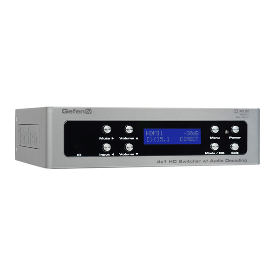
FRONT PANEL LAYOUT Front Panel... -
Page 9: Front Panel Descriptions
FRONT PANEL DESCRIPTIONS This IR receiver will accept commands from the included IR Remote Control Unit. Input ◄ This button cycles through all video and audio inputs. For each video input, audio may be selected from the embedded HDMI audio, or the coax, optical, or L/R analog audio inputs. Volume ▼ This button is used to decrease the volume level of the audio outputs when not in the Menu System. While in the Menu System this button will cycle down through the current level’s options. Mode / OK This button will change the audio processing mode. This button serves as a confirmation button when using the Menu System. Exit This button is used to exit the current menu level and return to the previous/ parent level. This button will exit the entire Menu System when on the top most level. Power Press this button to power ON the Switcher or place it in Standby mode. Power Indicator This LED will indicate the current power state. When the LED is red, the unit is in standby mode. When the LED is green, the unit is on. Menu This button will activate the Menu System which is where all adjustment and settings will be made. Main LCD Display This display will show pertinent status information and will be used to make adjustments to features in the Menu System. 10 Volume ▲ This button is used to increase the volume level of the audio outputs when not in the Menu System. While in the Menu System this button will cycle up through the current level’s options. 11 Mute ► This button will cycles between Mute-On and Mute-Off modes. When the Mute-On mode is enabled, all audio output will be ceased. While in the Menu System this button will cycle through available options in the right direction when a feature has been selected for adjustment. -
Page 10: Back Panel Layout
BACK PANEL LAYOUT Back Panel... -
Page 11: Back Panel Descriptions
BACK PANEL DESCRIPTIONS Line Out (Front Bi-Amp) Two RCA audio output connectors available for front-channel bi-amping purposes. The output signal is identical to the Front L/R outputs. Line Out (Surround, Sub, Front) 8 RCA-type audio outputs are available for connection to a separate amplifier. Up to 6 discrete channels can be utilized. Line In L/R RCA-type audio inputs for analog audio. Optical In Use an optical cable to connect an external digital audio source to this TOSLINK connector. RS-232 This port is used to control functions and features using serial communications. For more information on this feature please see page 42. Ext IR Connect an IR extender (Gefen Part No. EXT-RMT-EXTIR) to this port to extend the IR range if this product. Trigger Out Provides 11.5 V DC when the Switch is powered ON. This trigger can be used to control an external power amplifier, lights, curtains, etc. Trigger In Used to externally power the unit ON or OFF. This trigger will power ON the Switcher when a 3 V - 12 V DC voltage is applied. If the existing voltage is removed, then the Switcher is placed in Standby Mode (consumes less than < 1 W). 24V DC Connect the included 24 V DC power supply to this power receptacle. Only use the power supply that is included with this product. 10 HDMI In (1 - 4) Use these ports to connect and switch between four HDMI devices. 11 HDMI Out Connect an HDMI output device to this port. 12 Coax In Use a coax audio cable to connect an external digital audio source to this... -
Page 12: Ir Remote Description
IR REMOTE DESCRIPTION GTV-AUD-NIR IR Remote Control Unit Mute This button cycle between mute on and mute off modes. When mute is applied there will not be any audio output. Mode This button functions the same as the Mode button on the front panel. Enter Confirms the current selection setting. ◄ (Cursor Left) This button will navigate left when using the Menu System. Exit This button functions the same as the Exit button on the front panel. ▼ (Cursor Down / Decrease Volume) This button will navigate down through options when using the Menu System and will increase the volume when not in the Menu System. L/R Press this button to select the analog L/R audio input source. The current video source will not change. - Page 13 IR REMOTE DESCRIPTION Coax Press this button to select the S/PDIF audio input source. The current video source will not change. Optical Press this button to select the S/PDIF audio input source. The current video source will not change. 10 HDMI 1234 Press this button cycle between each of the HDMI input sources. The audio output will follow the HDMI source. 11 Info / Test Tone This button will display a series of information messages on the LCD screen when pressed. When adjusting the Speaker Level, this button will activate a test tone that is useful for adjusting the volume level of each speaker. 12 Enhance This button will cycle through audio enhancement presets. See page 32 for details on the available presets. 13 ► (Cursor Right) This button will navigate right when using the Menu System. 14 Menu This button will activate the Menu System which is where all adjustment and settings will be made. 15 ▲ (Cursor Up / Increase Volume) This button is used to increase the volume level of the audio outputs when not in the Menu System. While in the Menu System this button will cycle up through the current level options. 16 Power This button will toggle between the ON and STANDBY power states. An LED status indicator will signify the current power state. A RED LED will be active when the unit is in Standby power state. A GREEN LED will be active when the unit is in the ON power state. 17 Activity Indicator This LED will be activated momentarily each time a button is pressed.
-
Page 14: Ir Remote Installation
IR REMOTE INSTALLATION Installing the Battery 1. Remove the battery cover on the back of the IR Remote Control Unit. 2. Insert the included battery into the open battery slot. The positive (+) side of the battery should be facing up. 3. Replace the battery cover. The Remote Control unit ships with two batteries. One battery is required for operation and the other battery is a spare. Battery Slot (shown with battery) WARNING: Risk of explosion if battery is replaced by an incorrect type. Dispose of used batteries according to the instructions. -
Page 15: Ir Remote Configuration
IR REMOTE CONFIGURATION How to Resolve IR Code Conflicts In the event that IR commands from other remote controls interfere with the supplied IR Remote Control unit, changing the IR Remote Control’s IR channel will fix the problem. The IR Remote Control unit has a bank of DIP switches used for setting the IR channel. The DIP switch bank is located underneath the battery cover. Left: Picture of the opened rear battery compartment of the IR remote showing the exposed DIP Switch bank between the battery chambers. Corresponding DIP Switch Settings for each IR Channel IR Channel 0 (default) IR Channel 1 IR Channel 2 IR Channel 3 It is important that the IR channel on the Remote Control unit, matches the IR channel set on the 4x1 HD Switcher w/ Audio Decoding. For example, if both DIP switches on the IR Remote Control unit are set to IR channel 0 (both DIP switches down), then the 4x1 HD Switcher w/ Audio Decoding must also be set to IR channel 0. See page 38 on how to change the IR channel on the 4x1 HD Switcher w/ Audio Decoding. -
Page 16: Connecting The 4X1 Hd Switcher W/ Audio Decoding
S/PDIF AUDIO CABLE SPEAKER CABLE Game Console TRIGGER CABLE IR Extender RS-232 CABLE Electric Screen Cable Box HDMI CABLE GTV-AUDDEC-N Blu-ray Player C - N D D E - A U G T V HD Display Amplifier [D II] 1 0 8... -
Page 17: Operating The 4X1 Hd Switcher W/ Audio Decoding
OPERATING THE 4X1 SWITCHER W/ AUDIO DECODING Status Screen The Status Screen displays information regarding the current settings of the Switcher. The Status Screen is also used in conjunction with navigating the built-in Menu System. After powering on the Switcher, the Standby Screen will be displayed. The Standby Screen indicates the currently selected A/V input, the current volume setting, the audio input format, and the audio processing mode: A/V Input Audio Gain Displays the currently selected Displays the audio Audio and Video inputs gain (volume) H1 HD -10db None Direct Input Format Audio Mode Displays the Displays the current audio audio input format processing mode Standby Mode and Powering the Switcher Once the power supply is connected and the AC power cord is connected to an available electrical outlet, the Power Indicator will glow bright red. When the Power Indicator is red, the Switcher is Standby Mode. - Page 18 OPERATING THE 4X1 SWITCHER W/ AUDIO DECODING Selecting the Input Source Press the Input ◄ button to cycle through each input source. The table below lists which inputs are active for each selection. A/V Input Displays the currently selected A/V input H1 HD -10db None Direct This Switcher has four HDMI inputs (1 - 4) and three options for audio (coax, optical, and analog stereo). The following table lists the available video and audio inputs. Display Video Audio Display Video Audio H1_HD HDMI In 1 HDMI H3_HD HDMI In 3 HDMI H1_CX Coax H3_CX Coax H1_OT...
-
Page 19: Adjusting The Volume
OPERATING THE 4X1 SWITCHER W/ AUDIO DECODING Adjusting the Volume Use the Volume ▲ and Volume ▼ buttons to increase or decrease the audio output gain. The ▲ or ▼ buttons on the IR Remote Control can also be used to control the audio output gain. Audio gain can be reduced to a minimum of -60 dB and to a maximum of +10 dB. Each time these buttons are pressed, the volume is increased or decreased by 1 dB. TIP: To increase or decrease the audio gain at a faster rate, press and hold down either the Volume ▲ or Volume ▼ button until the desired volume is achieved. Increase Current Volume Volume H1 HD -10db None Direct Decrease Volume Muting the Audio Output Use the Mute button on the front panel or on the IR Remote Control to mute the audio output. The display will indicate if the audio is muted. To disable the mute function, press the Mute button again. The Volume ▲ and Volume ▼ buttons can also be used to disable muting. Mutes Indicates Audio Output Audio is muted H1 HD MUTE -10db... -
Page 20: Changing The Audio Processing Mode
OPERATING THE 4X1 SWITCHER W/ AUDIO DECODING Changing the Audio Processing Mode Successively press the Mode / OK button on the front panel to cycle through the different audio processing modes. The Mode button on the IR Remote Control can also be used to cycle through the audio modes. H1 HD -10db None Direct Displays Press to change current audio audio mode mode See page 25 for a description of each of the available audio processing modes. Main Menu To access the Menu System, press the Menu button on the front panel. The front-panel display will change: Press to display Menu system MAIN MENU SPEAKER SIZE Current Press to Press to Sub-menu access... -
Page 21: Menu System
MENU SYSTEM Using the Menu System The 4x1 HD Switcher w/ Audio Decoding comes with a built-in menu system which provides control over additional audio features. The following examples demonstrate some of the more common features of the Switcher. Setting the Speaker Size Adjusting the speaker size determines how each speaker handles low frequency bands. All speakers except the front left and right channels have an option to disable the use of that channel. If the center, read surround, or subwoofer channels are not going to be used there speakers should be set to the OFF setting. Source audio that uses these channels will be properly mixed to the other available speakers. A full summary of the Menu System can be found starting on page 69. Using the front-panel buttons 1. Press the Menu button. The front-panel display will change to display the Speaker Size menu: MAIN MENU SPEAKER SIZE 2. Press the Mode / OK button. The front-panel display will show the Front Left / Front R speaker size: SPEAKER SIZE FRONT L/R(LARGE) 3. Press the Mute ► or Input ◄ button to change the speaker size. - Page 22 MENU SYSTEM Using the IR Remote Control 1. Press the MENU button. The front-panel display will change to display the Speaker Size menu: MAIN MENU SPEAKER SIZE 2. Press the ENTER button. The front-panel display will show the Front Left / Front R speaker size: SPEAKER SIZE FRONT L/R(LARGE) 3. Press the ◄ or ► buttons to change the speaker size. SPEAKER SIZE FRONT L/R(SMALL) 4. Use the ▲ or ▼ buttons to change the size of the Center, Surround Left / Surround Right, and Subwoofer speakers. 5. Press the EXIT button to save the changes and return to the Speaker Size menu. MAIN MENU SPEAKER SIZE...
-
Page 23: Setting The Speaker Level
MENU SYSTEM Setting the Speaker Level Modifying the Speaker Level increases or decreases the audio output gain of a specific speaker. This feature is useful for equalizing the sound at the listening position. By default, each speaker’s output is set to 0 dB. The output can be adjusted by 1 dB increments between -10 dB and +10 dB. Using the front-panel buttons 1. From the Standby Screen, press the Menu button. Use the Volume ▲ or Volume ▼ buttons to navigate to the Speaker Level menu: MAIN MENU SPEAKER LEVEL 2. Press the Mode / OK button. The front-panel display will show the Front Left speaker level: SPEAKER LEVEL FRONT L (+00db) 3. Press the Mute ► or Input ◄ button to change the output gain of the Front Left speaker. SPEAKER LEVEL FRONT L (+02db) 4. Use the Volume ▲ or Volume ▼ buttons to cycle through the Center, Front Right, Surround Right, Surround Left, and Subwoofer and adjust the output... - Page 24 MENU SYSTEM Using the IR Remote Control When using the IR Remote Control, the INFO | TEST TONE button can be used to produce a White Noise test tone in order to adjust the output level. The test tone can also be enabled / disabled via RS-232 (see page 65). 1. Press the MENU button. The front-panel display will change to display the Speaker Level menu: MAIN MENU SPEAKER LEVEL 2. Press the ENTER button. The front-panel display will show the Front Left speaker level: SPEAKER LEVEL FRONT L (+00db) 3. Press the INFO | TEST TONE button on the IR Remote Control to enable the White Noise test tone. 4. Press the ◄ or ► buttons to adjust the output gain of the Front Left speaker. SPEAKER LEVEL FRONT L (+02db) Once the desired output level has been set, press the INFO | TEST TONE button on the IR Remote Control to enable the test tone.
-
Page 25: Setting The Speaker Distance
MENU SYSTEM Setting the Speaker Distance Changing the speaker distance is necessary for providing the proper audio delay when using the various audio processing modes. The distance for each speaker can be set in 1.5 foot (0.5 meter) increments within a range of 0 feet - 33 feet (10 meters). Speaker distance can be viewed in feet or meters. See page 34 for information on changing the preferred unit of measure on the Switcher. Using the front-panel buttons 1. From the Standby Screen, press the Menu button. Use the Volume ▲ or Volume ▼ buttons to navigate to the Speaker Distance menu: MAIN MENU SPEAKER DISTANCE 2. Press the Mode / OK button. The front-panel display will show the current distance for the Front Left speaker: SPEAKER DISTANCE FRONT L (03.0m ) 3. Press the Mute ► or Input ◄ button to change the distance of the Front Left speaker. - Page 26 MENU SYSTEM Using the IR Remote Control 1. From the Standby Screen, press the MENU button. Use the ▲ or ▼ buttons to navigate to the Speaker Distance menu: MAIN MENU SPEAKER DISTANCE 2. Press the ENTER button. The front-panel display will show the current dis- tance for the Front Left speaker: SPEAKER DISTANCE FRONT L (03.0m ) 3. Press the ◄ or ► buttons to change the distance of the Front Left speaker. SPEAKER DISTANCE FRONT L (04.5m ) 4. Use the ▲ or ▼ buttons to cycle through the Center, Front Right, Surround Right, Surround Left, and Subwoofer and adjust the speaker distance as necessary. 5. Press the EXIT button to save the changes and return to the Speaker Level menu. MAIN MENU SPEAKER DISTANCE...
-
Page 27: Adjusting The Tone Control
MENU SYSTEM Adjusting the Tone Control The Tone Control menu allows the adjustment of the treble and bass on the output signal. Treble and bass can be increased or decreased in 1 dB intervals, within a range of -12 dB to +12 dB. Using the front-panel buttons 1. From the Standby Screen, press the Menu button. Use the Volume ▲ or Volume ▼ buttons to navigate to the Tone Control menu: MAIN MENU TONE CONTROL 2. Press the Mode / OK button. The front-panel display will show the current bass setting. TONE CONTROL BASS (+01db) 3. Press the Mute ► or Input ◄ button to change the bass setting. TONE CONTROL BASS (-02DB) 4. Use the Volume ▲ or Volume ▼ buttons to navigate to the Treble setting and adjust the level as necessary. - Page 28 MENU SYSTEM Using the IR Remote Control 1. From the Standby Screen, press the MENU button. Use the ▲ or ▼ buttons to navigate to the Tone Control menu: MAIN MENU TONE CONTROL 2. Press the ENTER button. The front-panel display will show the current bass setting. TONE CONTROL BASS (+01db) 3. Press the ◄ or ► button to change the bass setting. TONE CONTROL BASS (-02DB) 4. Use the ▲ or ▼ buttons to navigate to the Treble setting and adjust the level as necessary. 5. Press the EXIT button to save the changes and return to the Tone Control menu. MAIN MENU TONE CONTROL...
-
Page 29: Saving Audio Processing Favorites
MENU SYSTEM Saving Audio Processing Favorites The 4x1 Switcher w/ Audio Decoding, allows any of five audio processing modes to be associated with a selected input. For example, you may want to associate the Multichannel Stereo audio processing mode with the optical (TOSLINK) input. On the other hand, you may want to set the Dolby Pro Logic II (PLII) audio processing mode when using the analog L/R inputs, in order to create discrete multichannel audio when using a surround system. These two examples will be illustrated. Available Modes Mode Description Audio playback without any processing (default setting). The input signal is the same as the output signal. DIRECT Multichannel audio is down-mixed to two-channel audio and routed to the Front Left / Front Right speakers. STEREO Mixes the SL and FL channels to the Front Left Speaker; Mixes the SR and FR channels to the Front Right Speaker. If the Center channel is present, then the Front Left, Front Right, and Center channel will be used to produce a stereo MCH STER image. If the Center channel is not present, then only the Front Left and Front Right speakers will produce the stereo image. If the Center channel speaker is present (or enabled), the audio is played only through the Center channel (the Front Left and Front Right speakers will be muted). If the Center channel speaker is not present (or disabled), Front Left MONO and Front Right signals will be combined and played out of the Front Left and Front Right speaker. Transforms two-channel stereo into high-quality 5.1-channel surround sound. - Page 30 MENU SYSTEM Using the front-panel buttons Example 1: Assigning the optical (TOSLINK) input with the Multichannel Stereo audio processing mode: 1. From the Standby Screen, press the Menu button. Use the Volume ▲ or Volume ▼ buttons to navigate to the Audio Setup menu: MAIN MENU AUDIO SETUP 2. Press the Mode / OK button. The front-panel display will display the coaxial option: AUDIO SETUP COAXIAL FAV PROC 3. Use the Volume ▼ button to navigate to the optical option: AUDIO SETUP OPTICAL FAV PROC 4. Press the Mute ► or Input ◄ button to access the current setting for the...
- Page 31 MENU SYSTEM Example 2: Assigning the analog L/R inputs with the Dolby Pro Logic II audio processing mode: 1. Starting from Step 5, above, use the Volume ▼ button to navigate to the analog L/R option: AUDIO SETUP AUD LR FAV PROC 2. Press the Mute ► or Input ◄ button to access the current setting for the analog L/R input. In the illustration below, the analog L/R input is set to use the Stereo audio processing mode: AUD LR FAV PROC AUD LR( STEREO ) 3. Press the Mute ► or Input ◄ button to change the current (favorite) setting from Stereo to PLII (Dolby Pro Logic II): AUD LR...
- Page 32 MENU SYSTEM Using the IR Remote Control Example 1: Assigning the optical (TOSLINK) input to use the Multichannel Stereo audio processing mode: 1. From the Standby Screen, press the MENU button. Use the ▲ or ▼ button to navigate to the Audio Setup menu: MAIN MENU AUDIO SETUP 2. Press the ENTER button. The front-panel display will display the coaxial option: AUDIO SETUP COAXIAL FAV PROC 3. Use the ▼ button to navigate to the optical option: AUDIO SETUP OPTICAL FAV PROC 4. Press the ► or ◄ button to access the current setting for the optical (TOSLINK) input. In the illustration below, the optical input is set to use the Direct audio...
- Page 33 MENU SYSTEM Example 2: Assigning the analog L/R inputs to use the Dolby Pro Logic II audio processing mode: 1. Starting from Step 5, on the previous page, use the ▼ button to navigate to the analog L/R option: AUDIO SETUP AUD LR FAV PROC 2. Press the ► or ◄ button to access the current setting for the analog L/R input. In the illustration below, the analog L/R input is set to use the Stereo audio processing mode: AUD LR FAV PROC AUD LR( STEREO ) 3. Press the ► or ◄ button to change the current (favorite) setting from Stereo to PLII (Dolby Pro Logic II): AUD LR...
-
Page 34: Dynamic Range Compression
MENU SYSTEM Dynamic Range Compression Dynamic Range Compression (DRC) applies compression to the output signal, preventing the signal from becoming too loud. This function only affects Dolby audio and not PCM. The default setting for Dynamic Range Compression is OFF. Using the front-panel buttons 1. From the Standby screen, press the Menu button. 2. Use the Volume ▲ or Volume ▼ buttons to navigate to the Audio Setup menu. MAIN MENU AUDIO SETUP 3. Press the Mode / OK button. 4. Use the Volume ▲ or Volume ▼ buttons to select the DRC option: AUDIO SETUP 5. Press the ◄ or ► button to change to enable DRC. AUDIO SETUP 6. Press the Exit button to save the changes and return to the Audio Setup menu. - Page 35 MENU SYSTEM Using the IR Remote Control 1. From the Standby screen, press the MENU button. 2. Use the ▲ or ▼ buttons to navigate to the Audio Setup menu. MAIN MENU AUDIO SETUP 3. Press the ENTER button. 4. Use the ▲ or ▼ buttons to select the DRC option: AUDIO SETUP 5. Press the ◄ or ► button to change to enable DRC. AUDIO SETUP 6. Press the EXIT button to save the changes and return to the Audio Setup menu.
-
Page 36: Audio Enhancement Modes
MENU SYSTEM Audio Enhancement Modes The 4x1 Switcher w/ Audio Decoding provides four distinct audio enhancement modes. Each of these modes provide a different audio listening experience. Available Modes Mode Description Increases the volume of quiet passages, while decreasing the volume of loud passages. Similar to Night DRC but works with all audio signals. Detects speech audio patterns and separates them from the background sounds, making them more VOICE intelligible. Real-time detection of the source audio gain, providing constant volume level between changing VOLUME channels and commercial advertisements. Disables audio enhancement mode. Using the front-panel buttons 1. From the Standby screen, press the Menu button. 2. Use the Volume ▲ or Volume ▼ buttons to navigate to the Audio Setup menu. MAIN MENU AUDIO SETUP 3. Press the Mode / OK button. 4. Use the Volume ▲ or Volume ▼ buttons to select the Enhancement option: AUDIO SETUP enha. - Page 37 MENU SYSTEM 5. Press the ◄ or ► button to change to change the audio enhancement mode. In the illustration below, the audio enhancement mode has been set to Night mode: AUDIO SETUP enha. ( NIGHT+) 6. Press the Exit button to save the changes and return to the Audio Setup menu. MAIN MENU AUDIO SETUP Using the IR Remote Control 1. From the Standby screen, press the MENU button. 2. Use the ▲ or ▼ buttons to navigate to the Audio Setup menu. MAIN MENU AUDIO SETUP 3. Press the ENTER button. 4. Use the ▲ or ▼ buttons to select the Enhancement option: AUDIO SETUP enha. 5. Press the ◄...
-
Page 38: Setting The Unit Of Measure
MENU SYSTEM Setting the Unit of Measure When adjusting the speaker distance, either feet or meters can be specified. Using the front-panel buttons 1. From the Standby Screen, press the Menu button. Use the Volume ▲ or Volume ▼ buttons to navigate to the Misc Setup menu. MAIN MENU MISC SETUP 2. Press the Mode / OK button. The front-panel display will show the current distance for the Front Left speaker: In the illustration below, the current unit of measure is set to meters. MISC MENU DIST.UNIT(METER) 3. To change the unit of measure to feet, press the Mute ► or Input ◄ button to change the unit of measure to feet. MISC MENU DIST.UNIT( FEET) 4. Press the Exit button to save the changes and return to the Misc Setup menu. - Page 39 MENU SYSTEM Using the IR Remote Control 1. From the Standby Screen, press the MENU button. Use the ▲ or ▼ buttons to navigate to the Misc Setup menu. MAIN MENU MISC SETUP 2. Press the ENTER button. The front-panel display will show the current distance for the Front Left speaker: In the illustration below, the current unit of measure is set to meters. MISC MENU DIST.UNIT(METER) 3. To change the unit of measure to feet, press the ◄ or ► button to change the unit of measure to feet. MISC MENU DIST.UNIT( FEET) 4. Press the EXIT button to save the changes and return to the Misc Setup menu. MAIN MENU MISC SETUP...
-
Page 40: Setting The Edid Mode
MENU SYSTEM Setting the EDID Mode The 4x1 Switcher w/ Audio Decoding has three EDID modes (INT, EXT, and MIX). • INT Mode The internal (local) EDID is used instead of the EDID from the display device. EDID features newer than HDMI 1.3 are removed from the EDID data structure when the display is read. This provides a general EDID which is compatible with more displays. • EXT Mode The external (downstream) EDID is used. In this mode, both DDC and HPD are passed through and the Switcher uses the full video capabilities of the display. The HPD status will also be detected by the source device. • MIX Mode The display capabilities from the external EDID are combined with the audio capabilities of the internal EDID of the Switcher. Using the front-panel buttons 1. To set the EDID mode, press the Menu button from the Standby screen. 2. Use the Volume ▲ or Volume ▼ buttons to navigate to the Misc Setup menu. MAIN MENU MISC SETUP 3. Press the Mode / OK button. - Page 41 MENU SYSTEM Using the IR Remote Control 1. To set the EDID mode, press the MENU button from the Standby screen. 2. Use the ▲ or ▼ buttons to navigate to the Misc Setup menu. MAIN MENU MISC SETUP 3. Press the ENTER button. 4. Use the ▲ or ▼ button to select the EDID adjustment menu. In the illustration below, the internal (INT) EDID is being used. MISC SETUP EDID ADJ.( INT ) 5. To change the EDID mode, press the ◄ or ► button to the desired EDID mode (below, the mixed-mode EDID has been selected). MISC SETUP EDID ADJ.( MIX ) 6. Press the EXIT button to save the changes and return to the Misc Setup menu. MAIN MENU MISC SETUP...
-
Page 42: Setting The Ir Channel
MENU SYSTEM Setting the IR Channel When controlling the 4x1 Switcher w/ Audio Decoding using the IR Remote Control Unit, the IR channel on the Switcher must be the same as the IR channel set on the IR Remote Control Unit. See page 11 on changing the IR channel on the IR Remote Control Unit. Using the front-panel buttons 1. From the Standby screen, press the Menu button. 2. Use the Volume ▲ or Volume ▼ buttons to navigate to the Misc Setup menu. MAIN MENU MISC SETUP 3. Press the Mode / OK button. 4. Use the Volume ▲ or Volume ▼ buttons to select the IR channel menu. In the illustration below, the IR channel is set to 1. MISC SETUP IR CHANNEL ( 1 ) 5. Press the Mute ► or Input ◄ buttons to change to the required IR channel. - Page 43 MENU SYSTEM Using the IR Remote Control 1. From the Standby screen, press the MENU button. 2. Use the ▲ or ▼ button to navigate to the Misc Setup menu. MAIN MENU MISC SETUP 3. Press the Mode / OK button. 4. Use the ▲ or ▼ button to select the IR channel menu. In the illustration below, the IR channel for the Switcher is set to 1. MISC SETUP IR CHANNEL ( 1 ) 5. Press the ◄ or ► button to change to the required IR channel. MISC SETUP IR CHANNEL ( 3 ) 6. Press the Exit button to save the changes and return to the Misc Setup menu.
-
Page 44: Resetting The Switcher To Factory Settings
MENU SYSTEM Resetting the Switcher to Factory Settings If the Switcher needs to be reset for any reason or if you need to set the unit to factory (default) settings, follow the instructions below. Using the front-panel buttons 1. From the Standby screen, press the Menu button. 2. Use the Volume ▲ or Volume ▼ buttons to navigate to the Misc Setup menu. MAIN MENU MISC SETUP 3. Press the Mode / OK button. 4. Use the Volume ▲ or Volume ▼ buttons to select the Factory Defaults option. MISC SETUP Factory Default 5. Press the Mode / OK button. The Switcher will prompt you to confirm the selection. -
Page 45: Factory Default
MENU SYSTEM Using the IR Remote Control 1. From the Standby screen, press the MENU button. 2. Use the ▲ or ▼ buttons to navigate to the Misc Setup menu. MAIN MENU MISC SETUP 3. Press the ENTER button. 4. Use the ▲ or ▼ buttons to select the Factory Defaults option. MISC SETUP Factory Default 5. Press the ENTER button. The Switcher will prompt you to confirm the selection. OK TO F.DEFAULT MENU TO CANCEL Press the ENTER button to reset the Switcher to factory (default) settings. If the Switcher is reset, the Switcher will power OFF and then automatically power ON after a few moments. Press the MENU button to cancel the reset process and return to the Standby screen. -
Page 46: Rs-232 Serial Control
RS-232 SERIAL CONTROL 5 4 3 2 1 1 2 3 4 5 9 8 7 6 6 7 8 9 Only Pins 2 (RX), 3 (TX), and 5 (Ground) are used on the RS-232 serial interface RS232 Settings Bits per second .................... 19200 Data bits ....................... 8 Parity ......................None Stop bits ........................1... -
Page 47: Rs-232 Serial Commands
RS-232 SERIAL COMMANDS Commands Command Description Selects between S/PDIF, TOSLink, or Analog audio input AUDIO BASS Increases or decreases the bass Sets the size of the Center speaker Sets the distance for the Center speaker Sets the distance for the Front Left speaker Sets the Switcher to factory (default) settings DFLT Sets the distance for the Front Right speaker Adjusts the Dynamic Range Control DSUB Sets the distance for the Subwoofer Sets the distance of the Left Surround speaker Sets the distance of the Right Surround speaker EDID Sets the EDID mode Sets the audio enhancement mode Sets the size of the Front Left / Front Right speakers HDMI Set the HDMI input Lists these RS-232 commands HELP INFO Returns hardware and firmware version INTYPE Returns the input audio format Sets the IR channel for the Switcher Sets the audio mode MUTE Enables / disables audio muting Powers the Switcher ON or OFF Sets the size of the Surround Left and Surround Right speakers Enables or disables auto status feedback STAT Enables / disables the subwoofer... - Page 48 RS-232 SERIAL COMMANDS AUDIO Command The AUDIO command assigns the external audio input. The AUDIO command does not have any effect on the video input. See page 54 for information on changing the video source. Syntax: AUDIO param1 Parameters: param1 Port [0 ... 3] Value Meaning HDMI S/PDIF TOSLink Analog RCA Returns: HDMI param1 param1 Meaning HDMI audio Coax (S/PDIF) audio Optical (TOSLINK) audio Analog L/R audio The value x represents the current HDMI input selection. For example, if the Switcher is using HDMI Input 2 with the optical (TOSLINK) audio input, the return value would be HDMI +22. Notes: HDMI is the return prefix for the AUDIO command. See the HDMI command on page 54 for further reference. Use ? for param1 to retrieve the current value.
- Page 49 RS-232 SERIAL COMMANDS BASS Command The BASS command sets the bass level. Syntax: BASS param1 Parameters: param1 Level [-12 ...12] Returns: BASS value Value Meaning -12 ... +12 Bass level Notes: The + or - character can also be used, instead of specifying a value, in order to increase or decrease the bass level by 1 dB. Use ? for param1 to retrieve the current value. Example: bass + // increases the bass level by 1 dB bass - // decreases the bass level by 1 dB bass 5 // sets the bass level to +5 dB...
- Page 50 RS-232 SERIAL COMMANDS CT Command The CT command sets the state of the Center speaker. Syntax: CT param1 Parameters: State [0 ... 2] param1 Value Meaning Small Center speaker Large Center speaker Returns: CT param1 param1 Meaning Small Center speaker Large Center speaker Center Speaker OFF Notes: Use ? for param1 to retrieve the current value. DC Command The DC command sets the distance of the Center speaker. Syntax: DC param1 Parameters: param1 Distance [0 ... 20]...
- Page 51 RS-232 SERIAL COMMANDS Returns: DC param1 Notes: Distance is measured in feet. Use ? for param1 to retrieve the current value. DFL Command The DFL command sets the distance of the Front Left speaker. Syntax: DFL param1 Parameters: Distance [0 ... 20] param1 Returns: DFL param1 Notes: Distance is measured in feet. Use ? for param1 to retrieve the current value.
- Page 52 RS-232 SERIAL COMMANDS DFLT Command The DFLT command sets the unit to the default settings. Syntax: DFLT 1 Parameters: None Returns DFLT Notes: The value of 1 must be specified as a parameter. DFR Command The DFR command sets the distance for the Front Right speaker. Syntax: DFR param1 Parameters: param1 Distance [0 ... 20] Returns: DFR param1 Notes: Distance is measured in feet. Use ? for param1 to retrieve the current value.
- Page 53 RS-232 SERIAL COMMANDS DRC Command The DRC command enables or disables Dynamic Range Control. Syntax: DRC param1 Parameters: param1 Value Value Meaning Turn DRC OFF Turn DRC On Returns: DRC param1 param1 Meaning DRC +00 DRC is OFF DRC +01 DRC is ON Notes: Use ? for param1 to retrieve the current value.
- Page 54 RS-232 SERIAL COMMANDS DSB Command The DSB command sets the distance for the Subwoofer. Syntax: DSB param1 Parameters: param1 Distance [0 ... 20] Returns: DSB param1 Notes: Distance is measured in feet. Use ? for param1 to retrieve the current value. DSL Command The DSL command sets the distance for the Surround Left speaker. Syntax: DSL param1 Parameters: Distance [0 ... 20] param1 Returns: DSL param1 Notes: Distance is measured in feet. Use ? for param1 to retrieve the current value.
- Page 55 RS-232 SERIAL COMMANDS DSR Command The DSR command sets the distance for the Surround Right speaker. Syntax: DSR param1 Parameters: param1 Distance [0 ... 20] Returns: DSR param1 Notes: Distance is measured in feet. Use ? for param1 to retrieve the current value. EDID Command The EDID command sets the EDID mode. Syntax: EDID param1 Parameters: Mode [0 ... 2] param1 Value Meaning EDID Mix Internal EDID External EDID Returns: EDID param1...
- Page 56 RS-232 SERIAL COMMANDS Returns: EDID param1 param1 Meaning EDID +00 Mix Mode EDID +01 Internal EDID Mode EDID +02 External EDID Mode Notes: Internal EDID will use the built-in EDID of the Switcher. External EDID uses the downstream EDID of the display. The EDID Mix Mode will use the full video capabilities of the display and combine the full audio capabilities of the Internal EDID of the Switcher. The Switcher will power-cycle after the command has been issued. Use ? for param1 to retrieve the current value. ENH Command The ENH command sets the audio enhancement mode. Syntax: ENH param1 Parameters: param1 Mode [0 ... 20] Value Meaning Night Mode Voice Mode Volume Mode Audio Enhance OFF...
- Page 57 RS-232 SERIAL COMMANDS Returns: ENH Value Value Meaning ENH +00 Night Mode ENH +01 Voice Mode ENH +02 Volume Mode ENH +03 ENH Mode OFF Notes: Use ? for param1 to retrieve the current value. FLR Command The FLR command sets the size for the Front Left / Front Right speakers. Syntax: FLR param1 Parameters: param1 Size [0 ... 1] Value Meaning Small Front Speakers Large Front Speakers Returns: FLR Value Value Meaning Small Front Speakers Large Front Speakers Notes: Use ? for param1 to retrieve the current value.
- Page 58 RS-232 SERIAL COMMANDS HDMI Command The HDMI command sets the active HDMI input. The HDMI command does not have any effect on the audio input. See page 44 for information on changing the audio source. Syntax: HDMI param1 Parameters: param1 Input [1 ... 4] Input Meaning HDMI Input 1 HDMI Input 2 HDMI Input 3 HDMI Input 4 Returns: HDMI param1 param1 Meaning Set to HDMI Input 1 Set to HDMI Input 2 Set to HDMI Input 3 Set to HDMI Input 4 Notes: When executing the HDMI command, the audio will default to HDMI (embedded) audio. Use the AUDIO command (see page 44) to change the audio input. Use ? for param1 to retrieve the current value.
- Page 59 RS-232 SERIAL COMMANDS HELP Command The HELP command lists the RS-232 command set. Syntax: HELP ? Parameters: None Notes: The ? character must be specified as a parameter. INFO Command The INFO command returns hardware and firmware version. Syntax: INFO ? Parameters: None Notes: The ? character must follow the command.
- Page 60 RS-232 SERIAL COMMANDS INTYPE Command The INTYPE command returns the audio input format. Syntax: INTYPE ? Parameters: None Returns: Value [0 ... 4] Value Meaning None PCM 2.1 PCM 5.1 Dolby Digital 2.1 Dolby Digital 5.1 Notes: The ? character must follow the command.
- Page 61 RS-232 SERIAL COMMANDS IR Command The IR command sets the IR channel for the Switcher. Syntax: IR param1 Parameters: param1 Channel [0 ... 3] Input Meaning IR Channel 1 IR Channel 2 IR Channel 3 IR Channel 4 Returns: IR Value Value Meaning IR Channel 1 IR Channel 2 IR Channel 3 IR Channel 4 Notes: Use ? for param1 to retrieve the current value.
- Page 62 RS-232 SERIAL COMMANDS MD Command The MD command sets the audio mode. Syntax: MD param1 Parameters: param1 Mode [0 ... 4] Mode Meaning Pro Logic Surround Direct Input Downmix to Stereo L/R Multichannel Surround Downmix to Mono Returns: MD param1 Mode Meaning Pro Logic Surround Direct Input Downmix to Stereo L/R Multichannel Surround Downmix to Mono Notes: Use ? for param1 to retrieve the current value.
- Page 63 RS-232 SERIAL COMMANDS MUTE Command The MUTE command sets the audio mode. Syntax: MUTE param1 Parameters: param1 Mode [0 ... 3] Mode Meaning Disable mute Volume set to minimum Mute toggle Returns: Using RS-232, the following values are returned Value Meaning MUTE +00 Mute is OFF MUTE +01 Mute is ON MUTE +00 Mute toggled OFF MUTE +01 Mute toggled ON Notes: Setting param1 to 2 will toggle the current audio muting state. Use ? for param1 to retrieve the current value.
- Page 64 RS-232 SERIAL COMMANDS PWR Command The PWR command turns the Scaler ON or OFF. Syntax: PWR param1 Parameters: param1 Mode [0 ... 2] Mode Meaning Power save mode Power On Toggle power state Returns: Using RS-232, the following values are returned Value Meaning PWR +00 Power save mode ON PWR +01 Power save mode OFF PWR +00 Power toggled OFF PWR +01 Power toggled ON Notes: Setting param1 to 2 will automatically toggle the current power state. Use ? for param1 to retrieve the current value.
- Page 65 RS-232 SERIAL COMMANDS SLR Command The SLR command sets the size of the Surround Left / Surround Right speakers. Syntax: SLR param1 Parameters: param1 Size [0 ... 2] Size Meaning Small Surround speakers Large Surround speakers Disable Surround speakers Returns: SLR value Value Meaning Small Surround speakers Large Surround speakers Disable Surround speakers Notes: Use ? for param1 to retrieve the current value.
- Page 66 RS-232 SERIAL COMMANDS STAT Command The STAT command enables or disables auto status feedback. Syntax: STAT param1 Parameters: param1 Mode [0 ... 1] Mode Meaning Auto Status Off Auto Status On Returns: STAT value Value Meaning Auto Status Off Auto Status On Notes: Use ? for param1 to retrieve the current value.
- Page 67 RS-232 SERIAL COMMANDS SUB Command The SUB command enables or disables the subwoofer. Syntax: SUB param1 Parameters: param1 Mode [0 ... 1] Mode Meaning Subwoofer Off Subwoofer On Returns: SUB value Value Meaning Auto Status Off Auto Status On Notes: Use ? for param1 to retrieve the current value.
- Page 68 RS-232 SERIAL COMMANDS SUBV Command The SUBV command sets the volume level of the Subwoofer. Syntax: PWR param1 Parameters: param1 Range [-12 ... 12] Returns: SUBV value Value Meaning -12 ... +12 Subwoofer volume Notes: The + or - character can also be used, instead of specifying a value, in order to increase or decrease the subwoofer level by 1 dB intervals. Use ? for param1 to retrieve the current value.
- Page 69 RS-232 SERIAL COMMANDS TEST Command The TEST command plays a test tone to specified speaker zone Syntax: TEST param1 Parameters: param1 Zone [0 ... 6] Zone Meaning Test tone to Front Left Test tone to Center Test tone to Front Right Test tone to Surround Right Test tone to Surround Left Test tone to Subwoofer Turn off current test tone Returns: TEST value Value Meaning Test tone to Front Left Test tone to Center Test tone to Front Right Test tone to Surround Right Test tone to Surround Left Test tone to Subwoofer Turn off current test tone Notes: The command test 6 must be invoked to halt the current test tone. The test tone can only be sent to one zone at a time (multiple zones cannot play test tones).
- Page 70 RS-232 SERIAL COMMANDS TREB Command The TREB command sets the treble level. Syntax: TREB param1 Parameters: param1 Range [-12 ... 12] Returns: TREB value Value Meaning -12 ... +12 Treble setting Notes: The + or - character can also be used, instead of specifying a value, in order to increase or decrease the treble level by 1 dB intervals. Use ? for param1 to retrieve the current value.
- Page 71 RS-232 SERIAL COMMANDS TVTYPE Command The TVTYPE command sets the video broadcast format. Syntax: TVTYPE param1 Parameters: param1 Format [0 ... 1] Format Meaning NTSC format PAL format Returns: TVTYPE value Value Meaning NTSC format PAL format Notes: Use ? for param1 to retrieve the current value.
- Page 72 RS-232 SERIAL COMMANDS VOL Command The VOL command sets the overall output volume level. Syntax: VOL param1 Parameters: param1 Range [-60 ... 12] Returns: VOL value Value Meaning -60 ... +12 Volume level Notes: The + or - character can also be used, instead of specifying a value, in order to increase or decrease the volume level by 1 dB intervals. Use ? for param1 to retrieve the current value.
-
Page 73: Menu System Summary
MENU SYSTEM SUMMARY Main Menu H1 HD -01db None direct Mode / OK ▲ MAIN MENU SPEAKER LEVEL ▲ Exit ▲ MAIN MENU SPEAKER DISTANCE ▲ Exit ▲ MAIN MENU TONE CONTROL ▲ Exit ▲ MAIN MENU AUDIO SETUP ▲ Exit ▲ MAIN MENU MISC SETUP ▲... - Page 74 MENU SYSTEM SUMMARY Exit ▲ MAIN MENU EXIT Exit ▲...
-
Page 75: Speaker Size Menu
MENU SYSTEM SUMMARY Speaker Size Menu MAIN MENU SPEAKER SIZE Mode / OK ▲ SPEAKER SIZE FRONT L/R(SMALL) ▲ Exit ▲ SPEAKER SIZE CENTER (SMALL) ▲ Exit ▲ SPEAKER SIZE SURR L/R (SMALL) ▲ Exit ▲ SPEAKER SIZE (SMALL) ▲ Exit ▲ SPEAKER SIZE EXIT Exit... -
Page 76: Speaker Level Menu
MENU SYSTEM SUMMARY Speaker Level Menu MAIN MENU SPEAKER LEVEL Mode / OK ▲ SPEAKER LEVEL FRONT L (+00db) ▲ Exit ▲ SPEAKER LEVEL CENTER (+00db) ▲ Exit ▲ SPEAKER LEVEL Front R (+00db) ▲ Exit ▲ SPEAKER LEVEL SURR R (+00db) ▲... - Page 77 MENU SYSTEM SUMMARY Exit ▲ SPEAKER LEVEL (+10db) ▲ Exit ▲ SPEAKER LEVEL EXIT Exit ▲...
-
Page 78: Speaker Distance Menu
MENU SYSTEM SUMMARY Speaker Distance Menu MAIN MENU SPEAKER DISTANCE Mode / OK ▲ SPEAKER DISTANCE FRONT L (03.0m) ▲ Exit ▲ SPEAKER DISTANCE CENTER (02.0M) ▲ Exit ▲ SPEAKER DISTANCE Front R (03.0m) ▲ Exit ▲ SPEAKER DISTANCE SURR R (02.0m) ▲... - Page 79 MENU SYSTEM SUMMARY Exit ▲ SPEAKER DISTANCE (03.0m) ▲ Exit ▲ SPEAKER DISTANCE EXIT Exit ▲...
-
Page 80: Tone Control Menu
MENU SYSTEM SUMMARY Tone Control Menu MAIN MENU TONE CONTROL Mode / OK ▲ TONE CONTROL BASS (+05db) ▲ Exit ▲ TONE CONTROL TREBLE (+00db) ▲ Exit ▲ TONE CONTROL EXIT Exit ▲... -
Page 81: Audio Setup Menu
MENU SYSTEM SUMMARY Audio Setup Menu MAIN MENU AUDIO SETUP Mode / OK ▲ AUDIO SETUP COAXIAL FAV PROC ▲ Exit ▲ AUDIO SETUP OPTICAL FAV PROC ▲ Exit ▲ AUDIO SETUP AUD LR FAV PROC ▲ Exit ▲ AUDIO SETUP HDMI 1 FAV PROC ▲... - Page 82 MENU SYSTEM SUMMARY Exit ▲ AUDIO SETUP HDMI 3 FAV PROC ▲ Exit ▲ AUDIO SETUP HDMI 4 FAV PROC ▲ Exit ▲ AUDIO SETUP ( OFF ) ▲ Exit ▲ AUDIO SETUP ENHA. ( NIGHT+) ▲ Exit ▲ AUDIO SETUP EXIT Exit ▲...
-
Page 83: Misc Setup Menu
MENU SYSTEM SUMMARY Misc Setup Menu MAIN MENU MISC SETUP Mode / OK ▲ MISC SETUP DIST.UNIT(METER) ▲ Exit ▲ MISC SETUP EDID ADJ.(INT) ▲ Exit ▲ MISC SETUP TV SYSTEM( NTSC) ▲ Exit ▲ MISC SETUP IR ChANNEL ( 1 ) ▲... - Page 84 MENU SYSTEM SUMMARY Exit ▲ MISC SETUP EXIT Exit ▲...
-
Page 85: Specifications
SPECIFICATIONS Maximum Pixel Clock ................225 MHz Input DDC Signal ................. 5 Volts p-p (TTL) Single Link Range .......... 1080p/1920 x 1200 max. resolution Digital Audio Input ..............1 x S/PDIF coaxial HDMI Input ..............1 x HDMI Female 19-pin HDMI Outputs ..............2 x HDMI Female 19-pin Digital Audio Output ..............1 x S/PDIF coaxial Digital Audio Output ............... 1 x TOSLINK optical Analog Audio Outputs ................... 8 total (6 analog audio RCA jacks + 2 additional RCA jacks for Bi-Amp) Supported Audio Formats: Dolby Digital 5.1 (AC3), LPCM HDMI direct (up to 6 ch.) Audio Processing ............... Dolby Pro Logic II Signal To Noise Ratio ........> 90 dB (20Hz-20kHz A weight filter) THD+N ............. < 0.1% at 1 kHz at reference level Frequency Response ..........< +/- 0.5 dB 20 Hz - 20 kHz Power Supply .................... 24V DC Dimensions ............... 6.9” W x 2.1” H x 6.9” D Shipping Weight .................... 6 lbs. -
Page 86: Warranty
1. Proof of sale may be required in order to claim warranty. 2. Customers outside the US are responsible for shipping charges to and from Gefen. 3. Copper cables are limited to a 30 day warranty and cables must be in their original condition. The information in this manual has been carefully checked and is believed to be accurate. However, Gefen assumes no responsibility for any inaccuracies that may be contained in this manual. In no event will Gefen be liable for direct, indirect, special, incidental, or consequential damages resulting from any defect or omission in this manual, even if advised of the possibility of such damages. The technical information contained herein regarding the features and specifications is subject to change without notice. For the latest warranty coverage information, refer to the Warranty and Return Policy under the Support section of the Gefen Web site at www.gefen.com. PRODUCT REGISTRATION Please register your product online by visiting the Register Product page under the Support section of the Gefen Web site. - Page 88 Rev A3 20600 Nordhoff St., Chatsworth CA 91311 1-800-545-6900 818-772-9100 fax: 818-772-9120 www.gefentv.com support@gefentv.com This product uses UL listed power supplies.