Table of Contents
Advertisement
Quick Links
SERVICE MANUAL
SERVICE MANUAL
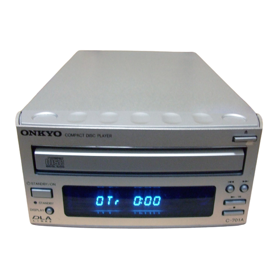
Compact Disc Player
C-701A
MODEL
/ ON
BY
Silver model
SMPP,SMGT
230-240V AC, 50Hz
SMDT
120V AC, 60Hz
SMGR
220-230V AC, 50/60Hz
SAFETY-RELATED COMPONENT
WARNING!!
COMPONENTS IDENTIFIED BY MARK
SCHEMATIC DIAGRAM AND IN THE PARTS LIST ARE
CRITICAL FOR RISK OF FIRE AND ELECTRIC SHOCK.
REPLACE THESE COMPONENTS WITH ONKYO
PARTS WHOSE PART NUMBERS APPEAR AS SHOWN
IN THIS MANUAL.
MAKE LEAKAGE-CURRENT OR RESISTANCE
MEASUREMENTS TO DETERMINE THAT EXPOSED
PARTS ARE ACCEPTABLY INSULATED FROM THE
SUPPLY CIRCUIT BEFORE RETURNING THE
APPLIANCE TO THE CUSTOMER.
C
701 A
ON THE
C-701A
Ref. No. 3696
092001
Advertisement
Table of Contents

Subscribe to Our Youtube Channel
Related Manuals for Onkyo C-701A


Summary of Contents for Onkyo C-701A
- Page 1 COMPONENTS IDENTIFIED BY MARK ON THE SCHEMATIC DIAGRAM AND IN THE PARTS LIST ARE CRITICAL FOR RISK OF FIRE AND ELECTRIC SHOCK. REPLACE THESE COMPONENTS WITH ONKYO PARTS WHOSE PART NUMBERS APPEAR AS SHOWN IN THIS MANUAL. MAKE LEAKAGE-CURRENT OR RESISTANCE...
-
Page 2: Protection Of Eyes From Laser Beam During Servicing
C-701A SERVICE PROCEDURES 1 PROTECTION OF EYES FROM LASER BEAM DURING SERVICING This set employs a laser. Therefore, be sure to follow Laser Diode Properties carefully the instructions below when servicing. Material: GaAS/GaAlAs Wavelength: 780nm WARNING!! Laser output: max. 0.5mW*... - Page 3 C-701A SERVICE PROCEDURES 2 1. Removement of tray 1. Remove the top cover 5. Press the tray stopper to the arrow mark direction and remove 2. Turn the locked screw to the clockwise to release the lock of gear. the tray ass'y. (Refer to fig-3)
-
Page 4: Specifications
C-701A SPECIFICATIONS Signal readout system : Optical non-contact Wow and Flutter : Below threshold of measurability Reading rotation : About 500 - 200 r.p.m. (constant linear velocity) Output level : 2 volts r.m.s. Linear velocity : 1.2 - 1.4 m/s... -
Page 5: Exploded View
C-701A EXPLODED VIEW P101 A705 A216 A210 P901 A216 A216 P701 A215 J904 A103 A216 P701 A103 <MGR>only A104 A101 A102 A105 <MGR>only F901 A204 A107 T901 A301 P701 A219 A108 <MPP>only A219 A203 A201 A219 A221 A219... -
Page 6: Exploded View Parts List
C-701A EXPLODED VIEW PARTS LIST-1 REF. NO. PART NO. DESCRIPTION 27100409 Chassis 27191158A Holder, PCB 838130088 Self tapping screw, 3TTB+8B 27190369 Holder, PCB 830440069 Self tapping screw, 4TTC+6C(BC) 27300750 Bushing, S-RELIEF #2271 27150476 Shield plate (PT) 880048 Plastic rivet, P-3055B-8L... - Page 7 C-701A EXPLODED VIEW PARTS LIST-2 REF. NO. PART NO. DESCRIPTION P901 253335HIT or Power cord, AS-CEE <MPP,MGT> 253336VOL 253332HIT or Power cord, AS-UC-2 <MDT> 253333VOL 253337HIT or Power cord, AS-CCEE <MGR> 253338VOL T901 2301553 Power transformer, NPT-1426P <MPP> 2301552 Power transformer, NPT-1426D <MDT>...
-
Page 8: Parts List
C-701A CD MECHANISM EXPLODED VIEW (1) PARTS LIST Ref. No. Part No. Description Ref. No. Part No. Description 2627-234-01 Insulator 2646-290-01 Tray Drive unit Stopper 2625-552-06 Main chassis 2625-544-01 Gear cover 2625-535-01 Tray Gear 3319-501-51 PTPWH2.6x16, Screw 2625-547-01 Drive Gear... - Page 9 C-701A CD MECHANISM EXPLODED VIEW (2) (Pickup drive unit) PARTS LIST Ref. No. Part No. Description X2625-984-1 Motor chassis ass'y X2625-769-1 Motor gear ass'y 2656-908-01 Sled shaft 2625-188-02 Gear A 7621-255-15 P2x3, Screw 1572-085-11 Leaf switch 1639-678-12 Motor PC board...
- Page 10 C-701A BLOCK DIAGRAM Q 4 0 2 O P T I C A L O U T O P A M P O P A M P R 1 2 3 + 5 V _ 2 Q 4 0 1...
- Page 11 C-701A SCHEMATIC DIAGRAM Main circuit PC board N A D G - 7 3 2 4 R 3 2 5 R 3 2 4 C 3 1 3 C 3 1 2 R 3 2 7 1 0 0 K...
-
Page 12: Schematic Diagram
SCHEMATIC DIAGRAM Main circuit PC board R 1 7 4 R 1 7 5 F O C U S G A I N R 1 2 4 R 1 2 3 T E S T - P O I N T 1 1 0 K B P 1 0 4 R 3 2 1... - Page 13 C-701A N A D G - 7 3 2 4 R 3 2 5 R 3 2 4 C 3 1 3 C 3 1 2 R 3 2 7 1 0 0 K Microprocessor circuit PC board 4 7 3 K 3 .
- Page 14 C-701A PC BOARD CONNECTION VIEW U5: Regulator circuit PC board P902 AC IN P903 JL905B MPP,MGT : 230-240V AC, 50Hz : 120V AC, 60Hz : 220-230V AC, 50/60Hz JL912B NAPS-7328 NAPS-7327 JL905A U2: Microprocessor : Driver circuit circuit PC board...
- Page 15 C-701A PRINTED CIRCUIT BOARD PARTS LIST-1 U2: Microprocessor circuit PC board U1: Main circuit PC board (NADG-7324-1B/1C/1D/1E) (NADG-7323-1B/1C/1D/1E) CIRCUIT NO. PART NO. DESCRIPTION CIRCUIT NO. PART NO. DESCRIPTION Q101 22241661R3 CXA2542AQ Q701 22241694R3 MPD78043FGF-087-3B9 Q301 22241500R3 CXD2589Q Q702 22241210 BMR-0101D...
- Page 16 C-701A PRINTED CIRCUIT BOARD PARTS LIST-2 U4: Display circuit PC board (NADIS-7326-1B/1C/1D/1E) U6: Power transformer PC board (NAPS-7328-1B/1C/1D/1E) CIRCUIT NO. PART NO. DESCRIPTION CIRCUIT NO. PART NO. DESCRIPTION FL tube Coils Q721 212224 HNA-09SS28T L901 231222 NCH-3454,Choke <MPP,MGR,MDT,MGT> D751 225338...
- Page 17 C-701A MICROPROCESSOR TERMINAL DESCRIPTION Q701: uPD78043FGF No. SIGNAL I/O DESCRIPTION No. SIGNAL I/O DESCRIPTION 36 STANDBY LED O Standby LED control terminal. H=ON, L=OFF 37 DSP RESET O Reset output terminal to signal processing IC. 38 POWER O Power source control output terminal. H=ON, L=OFF O Grid control output terminals(G3-G9) O Not used.
- Page 18 C-701A FL TUBE VIEW GRID ASSIGNMENT AUTO AUTO SLEEP SLEEP TIMER TIMER RDS (2G-9G) ANODE CONNECTION RDM MEM MEM RPT PIN CONNECTION PIN NO. 10 11 12 13 14 15 16 17 18 19 20 21 22 23 24 25 26 27 28 29 30 31 32 33 34 35...
-
Page 19: Adjustment Procedure
C-701A ADJUSTMENT PROCEDURE 1. SERVO ADJUSTMENT 1-1. Preparation Set the VR123 is center position. Connect the cables to the test point. (Fig.-1) 1-2. Focus gain adjustment Load the test disc (YEDS-18) on the tray and play the track 2. Adjust R123 until 1kHz the waveform of channels 1 and 2 on (Fig.-2) - Page 20 C-701A PACKING VIEW/ PARTS LIST PARTS LIST REF. NO. PART NO. DESCRIPTION REF. NO. PART NO. DESCRIPTION 29092023A Pad assy 2010375 or RI cable 29100123C Poly bag, 430 x 550 2010397 29110149 Cellophane tape 29343190 Instruction manual, E 29110098 PP tape 29343191 Instruction manual, U3FSI <MPP>...
- Page 21 Sales & Product Planning Div. : 2-1, Nisshin-cho, Neyagawa-shi, OSAKA 572-8540, JAPAN Tel: 072-831-8111 Fax: 072-833-5222 ONKYO U.S.A. CORPORATION 18 Park Way, Upper Saddle River, N.J. 07458, U.S.A. Tel: 201-785-2600 Fax: 201-785-2650 E-mail: onkyo@onkyousa.com ONKYO EUROPE ELECTRONICS GmbH Industriestrasse 20, 82110 Germering, GERMANY Tel: 089-849-320 Fax: 089-849-3265 E-mail: info@onkyo.de...
Need help?
Do you have a question about the C-701A and is the answer not in the manual?
Questions and answers