Table of Contents
Advertisement
Quick Links
Download this manual
See also:
Instruction Manual
Advertisement
Table of Contents

Related Manuals for AMX ALR-AMP-8


Summary of Contents for AMX ALR-AMP-8
- Page 1 IN STR U CT IO N MAN U AL A L R - A M P - 8 A LE RO 8 Z O N E STE RE O PO W E R A M P LI F I E R...
-
Page 2: Important Safety Instructions
COPYRIGHT NOTICE AMX© 2015, all rights reserved. No part of this publication may be reproduced, stored in a retrieval system, or transmitted, in any form or by any means, electronic, mechanical, photocopying, recording, or otherwise, without the prior written permission of AMX. Copyright protection claimed... - Page 3 Anyone performing field maintenance on AMX equipment should use an appropriate ESD field service kit complete with at least a dissipative work mat with a ground cord and a UL listed adjustable wrist strap with another ground cord WARNING: Do Not Open! Risk of Electrical Shock.
- Page 4 WEEE (recast) Directive 2012/19/EU; European Union Radio and Telecommunications Terminal Equipment (R&TTE) Directive 1999/5/EC. You may obtain a free copy of the Declaration of Conformity by visiting http://www.amx.com/techcenter/certifications.asp. WEEE NOTICE: This appliance is labeled in accordance with European Directive 2012/19/EU concerning waste of electrical and electronic equipment (WEEE).
-
Page 5: Table Of Contents
On Signal Output..............................17 12V Trigger ................................. 18 Pin 10 - Status GND ..........................18 On/Off Control (12V Trigger, 3-5V Trigger and Signal Sense) ........18 Enabling and Disabling Zones ..................18 ALR-AMP-8 Alero 8 Zone Power Amplifier - Instruction Manual... - Page 6 Applying Power to the Alero Amplifier ................19 AC Power Plug Connector........................19 Entering Standby Mode ........................19 NetLinx Programming Example: On Signal, OC and Thermal Functions ............20 Overview ......................... 20 ALR-AMP-8 Alero 8 Zone Power Amplifier - Instruction Manual...
-
Page 7: Alero Alr-Amp-8 8 Zone Power Amplifier
Alero ALR-AMP-8 8 Zone Power Amplif ier Overview The Alero ALR-AMP-8 8-Zone Power Amplifier (FG1104-01) features 16 distribution channels of true audiophile quality sound and highly efficient, heat-dissipating Class D power amplification – all smartly designed to fit into a compact 1RU chassis. Alero perfectly complements the AMX Precis DSP for a completely unified, whole-home distributed audio source switching and amplification solution. -
Page 8: Front Panel Components (Leds)
Channels 3/4 = Zone 2, etc), and the Thermal Protection LED will be lit. The other Zones will continue to be active. When the temperature has dropped below the thermal threshold, the respective Zone(s) start up again automatically. ALR-AMP-8 Alero 8 Zone Power Amplifier - Instruction Manual... -
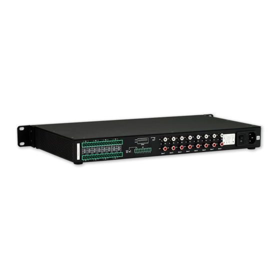
Page 9: Rear Panel Components
Matrix Switcher with Stereo Audio with RCA Digital Volume Control and Digital Signal Processing). The Alero ALR-AMP-8 can be powered on and off externally by using the two signals 12V trigger and 3-5V trigger. A Signal Sense function is also provided which automatically can switch on the Alero in the event of an audio signal and switch off the Alero to enter standby mode when no audio signal has been present on the signal terminals for approximately 13 minutes. -
Page 10: Installation
SE/BTL (Stereo/Bridge Mode) Switches (1-8) The ALR-AMP-8 features eight SE/BTL slide switches (located between the two RCA/phono input connectors for each Zone - see FIG. 4). These switches provide the ability to set each of the eight Zones to either Stereo Mode (SE) or Bridge Mode (BTL). Note that by default, all Audio Inputs are set to Stereo Mode. -
Page 11: Connecting Input Devices In Stereo Mode
The Alero ALR-AMP-8 supports up to eight stereo input devices, each one associated with an input Zone (1-8). Note that each Zone represents a stereo pair. For example, Zone 1 consists of CH1 (left channel) and Ch2 (right channel). -
Page 12: Connecting Speakers
The following table provides pinout information for the Speaker Output Terminals Speaker Output Terminals Pinout Information Function Description Type OUT+ Positive balanced audio power output terminal Output OUT- Negative balanced audio power output terminal Output ALR-AMP-8 Alero 8 Zone Power Amplifier - Instruction Manual... -
Page 13: Connecting Speakers In Stereo Mode
Even-numbered channels should be used to connect to the right speaker. The ALR-AMP-8 supports up to eight stereo speaker pairs, each one associated with a Zone (1-8). FIG. 8 illustrates the wiring connection from both Zone output channels to a stereo speaker pair:... -
Page 14: Connecting Speakers In Bridge Mode
CH11 (left) CH11 (+) / CH12 (+) CH13 (left) CH13 (+) / CH14 (+) CH15 (left) CH15 (+) / CH16 (+) See Also: Connecting Input Devices in Bridge Mode on page 11. ALR-AMP-8 Alero 8 Zone Power Amplifier - Instruction Manual... -
Page 15: I/O (Control Input) Port
Signal Sense can come from either output. The amplifier will power up if a signal is applied to the signal sense input. By default, the External Signal Switch is set to the ON position. ALR-AMP-8 Alero 8 Zone Power Amplifier - Instruction Manual... -
Page 16: Pin 3 - 12V (In) Trigger
When the 3-5V Trigger Switch is set to High, the amplifier will turn on when AC mains is turned on, For example, the 3-5V Trigger switch could be set to High if the amplifier needs to be forced on without having signal sense or external trigger signals. ALR-AMP-8 Alero 8 Zone Power Amplifier - Instruction Manual... -
Page 17: Pins 7 & 8 - Thermal Overload And Oc (Overcurrent) Monitor Indicators
Pin 9 Example Connection - On Signal Output Connections FIG. 16 NOTE: Refer to AMX Tech Note #777 for details regarding conf iguring the I/O ports on a NetLinx Master to accept a voltage input. ALR-AMP-8 Alero 8 Zone Power Amplifier - Instruction Manual... -
Page 18: 12V Trigger
On/Off Control (12V Trigger, 3-5V Trigger and Signal Sense) The Alero ALR-AMP-8 can be powered on and off externally by using the two signals 12V trigger and 3-5V trigger. A Signal Sense function is also provided which automatically can switch on the Alero in the event of an audio signal and switch off the Alero to enter standby mode when no audio signal has been present on the signal terminals for approximately 13 minutes. -
Page 19: Applying Power To The Alero Amplifier
Note that the POWER LED on the front panel lights Red to indicate that the amplifier is receiving power, but is in Standby mode. Also note that when in Standby mode, the 12V output trigger is turned off. ALR-AMP-8 Alero 8 Zone Power Amplifier - Instruction Manual... -
Page 20: Netlinx Programming Example: On Signal, Oc And Thermal Functions
// reflect the state of the amplifier on touch panel button 123 [dvTP,124] = [dvIO,2] // turn the button on when AMP8 is in Over Current Protection [dvTP,125] = [dvIO,3] // turn the button on when AMP8 is in Thermal shutdown ALR-AMP-8 Alero 8 Zone Power Amplifier - Instruction Manual... - Page 21 © 2015 Harman. All rights reserved. Alero, NetLinx, AMX, AV FOR AN IT WORLD, HARMAN, and their respective Last Revised: logos are registered trademarks of HARMAN. Oracle, Java and any other company or brand name referenced may 9/15/2015 be trademarks/registered trademarks of their respective companies.
Need help?
Do you have a question about the ALR-AMP-8 and is the answer not in the manual?
Questions and answers