Table of Contents
Advertisement
Quick Links
Download this manual
See also:
Instruction Manual
Overview
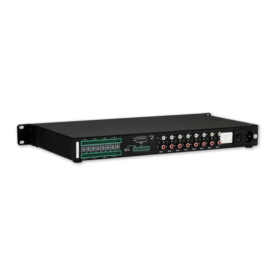
The Alero ALR-AMP-8 8-Zone Power Amplifier (FG1104-01) features 16 audio
distribution channels and Class D power amplification in a compact 1RU chassis.
Important Safety Instructions
Note: Please adhere to all of the following safety instructions:
1.
Read the instructions.
2.
Keep the instructions.
3.
Heed all warnings.
4.
Follow the instructions.
5.
Do not use this apparatus near water.
6.
Clean this apparatus only with a dry cloth.
7.
Do not block any ventilation openings. Install in accordance with the
manufacturer's instructions.
8.
Do not install near any heat sources such as radiators, heat registers, stoves, or
other apparatus (including amplifiers) that produce heat.
9.
Do not defeat the safety purpose of the grounding type plug. The grounding plug
has two blades and a third grounding prong. The third prong is provided for your
safety. If the provided plug does not fit into your outlet, consult an electrician for
replacement of the obsolete outlet.
10.
Protect the power cord from being walked on or pinched particularly at plugs,
convenience receptacles, and the point where they exit from the apparatus.
11.
Only use attachments/accessories specified by the manufacturer.
12.
Use only with cart, stand, tripod, bracket, or table specified by the manufacturer,
or sold with the apparatus. When a cart is used, use caution when moving the
cart/apparatus combination to avoid injury from tip-over.
13.
Unplug this apparatus during lightning storms or when unused for long periods
of time.
14.
Refer all servicing to qualified personnel. Servicing is required when the
apparatus has been damaged in any way, such as power supply cord or plug is
damaged, liquid has been spilled or objects have fallen into the apparatus, the
apparatus has been exposed to rain or moisture, does not operate normally, or
has been dropped.
15.
The appliance coupler is used as the disconnect device and shall remain readily
operable.
WARNING! To reduce the risk of fire or electric shock, do not expose this
apparatus to rain or moisture.
WARNING! This apparatus shall be connected to a MAINS socket outlet with
a protective earthing connection.
WARNING! This apparatus shall not be exposed to dripping or splashing,
and no objects filled with liquids, such as vases, shall be placed on the
apparatus.
DANGER! No user serviceable parts inside. Service is to be performed only
by AMX.
Safety Symbol Definitions
The exclamation point within an equilateral triangle is intended to alert the
user to the presence of important operating and maintenance (servicing)
instructions in the literature accompanying the product.
The lightning flash with arrowhead symbol within an equilateral triangle is
intended to alert the user to the presence of non-insulating, dangerous
voltage within the product's enclosure that may be of sufficient magnitude
to constitute a risk of electric shock to persons.
Certifications
The ALR-AMP-8 has the following safety certifications:
FCC, CE, UL, IEC, PSE, C-TICK.
Controlling the Alero ALR-AMP-8
Volume control for the ALR-AMP-8 is managed by an external pre-amp / audio
switcher, such as the AMX Precis DSP. The ALR-AMP-8 can be powered on and off
externally by using the two signals 12V trigger and 3-5V trigger.
A Signal Sense function is also provided which automatically can switch on the ALR-
AMP-8 in the event of an audio signal and switch off the ALR-AMP-8 to enter standby
mode when no audio signal has been present on the signal terminals for
approximately 13 minutes.
Refer to the Alero ALR-AMP-8 Instruction Manual for details on On/Off Control via the
12V Trigger, 3-5V Trigger and Signal Sense.
Note: The Alero ALR-AMP-8 requires an external preamp for volume control.
Front Panel Components (LEDs)
The front panel features three LEDs:
POWER LED (Green/Red)
Indicates the current power state of the amp (Green = On, Red = Standby mode)
OC/CLIP LED (Yellow/Red)
The OC/CLIP LED indicates that the current of one or more of the speaker outputs
has exceeded its maximum output:
ALR-AMP-8
•
Yellow indicates an OC (over-current) shutdown of the amplifier output.- In the
case of an OC event, the amplifier will shut down to protect itself, and indicate an
OC event on this LED (yellow) and the OC pin (pin 8 on the 10-pin I/O port).
An OC event can indicate a cable fault, installation fault or defective speaker.
•
Red indicates an over-current event with the Power Supply. The LED will light
red if internal temperature sensors on the power supply sense an abnormally
high temperature, or if power supply over-current/over-load/power-limit circuits
are triggered. In either case, the power supply will limit the amplifier output to
keep the power supply within safe limits, while keeping the music playing.
THERMAL LED (Red)
The Thermal Protection LED indicates if one or more of the speaker outputs are shut
down due to thermal protection.
•
The temperatures of all the output channels are individually monitored, and if
one or more of them reaches the thermal limit (105°C) then the respective Zones
will shut down and go into soft start mode (Channels 1/2 = Zone 1,
Channels 3/4 = Zone 2, etc), and the Thermal Protection LED will be lit.
•
The other Zones will continue to be active. When the temperature has dropped
below the thermal threshold, the respective Zone(s) start up again automatically.
Mounting the ALR-AMP-8 into an Equipment Rack
The ALR-AMP-8 can be mounted in a 19" equipment rack or on a solid flat surface.
Use the included removable rack ears and removable feet for mounting.
Ventilation
Note: The maximum operating ambient temperature is 45°C (113°F).
•
To ensure that the rack enclosure is adequately ventilated, there must be a
minimum of 3" all around the ALR-AMP-8
•
Sufficient airflow must be achieved (by convection or forced-air cooling) to
satisfy the ventilation requirements of all the items of equipment installed within
the rack.
Rack Mount Safety Instructions
•
Mounting of the equipment in the rack should be such that a hazardous
condition is not achieved due to uneven mechanical loading.
•
Consideration should be given to the connection of the equipment to the supply
circuit and the effect that overloading of the circuits might have on over current
protection and supply wiring. Appropriate consideration of equipment nameplate
ratings should be used when addressing this concern.
•
Reliable earthing of rack-mounted equipment should be maintained. Particular
attention should be given to supply connections other than direct connections to
the branch circuit (e.g. use of power strips).
Wiring and Connections
All speaker wire connections must be made with the amplifier off. The amplifier must
be off whenever you make changes to the input connections.
Connecting Audio Source Devices
Source Devices connect to the Input connectors on the rear panel. (FIG. 1):
Left Channel Inputs (Stereo Zones 1-8)
CH1, 3, 5, 7, 9, 11, 13 and 15 are used for inputs in Bridge Mode
Right Channel Inputs (Stereo Zones 1-8)
FIG. 1
Audio Input connectors (L/R pairs for 8 stereo inputs, 16 total)
•
The Audio Inputs consist of 16 RCA/phono terminals; each of the single-ended
input channels having a signal input and ground.
•
Each Zone (1-8) consists of two channels (odd and even) that represent the left
and right channels in a stereo pair. For example, CH1 and CH2 represent the left
and right channels for Zone 1.
Audio (Signal) Inputs
The following table provides pinout information for the Audio Inputs:
Audio Input Connectors - Pinout Information
PIN
Function
Description
1
Signal Sense +
Single Ended Signal Positive
2
Signal GND
Single Ended Signal GND
SE/BTL (Stereo/Bridge Mode) Switches (1-8)
The ALR-AMP-8 features eight SE/BTL slide switches (located between the two RCA/
phono input connectors for each Zone). These switches provide the ability to set each
of the eight Zones to either Stereo Mode (SE) or Bridge Mode (BTL). Note that by
default, all Audio Inputs are set to Stereo Mode.
•
Stereo Mode (SE): In Stereo Mode, both channels are used for stereo audio
input. Stereo mode provides true stereo separation between the left and right
channels in each Zone.
•
Bridge Mode (BTL): Bridge Mode uses one input channel of the amplifier to
combine the power from both channels output into one single output. In Bridge
Mode, the odd channels are used for audio input and the even channels are
disconnected internally.
Quick Start Guide
Alero 8 Zone Power Amplifier
SE/BTL
Stereo/Bridge Mode)
switches 1-8
(one per Zone)
Type
Input
GND
Advertisement
Table of Contents

Related Manuals for AMX ALR-AMP-8


Summary of Contents for AMX ALR-AMP-8
-
Page 1: Important Safety Instructions
Mounting the ALR-AMP-8 into an Equipment Rack replacement of the obsolete outlet. The ALR-AMP-8 can be mounted in a 19" equipment rack or on a solid flat surface. Protect the power cord from being walked on or pinched particularly at plugs, Use the included removable rack ears and removable feet for mounting. -
Page 2: Connecting Speakers
+12V Trigger (input) on a downstream amplifier. Trigger Out • When the ALR-AMP-8 is On, the output on Pin 4 will be +12V after 1 FIG. 2 Stereo Input - Zone 1 (CH1 and CH2) output on Speaker Outputs CH1 and CH2...
Need help?
Do you have a question about the ALR-AMP-8 and is the answer not in the manual?
Questions and answers