
Related Manuals for AMX ALR-AMP-8


Summary of Contents for AMX ALR-AMP-8
- Page 1 I n s t r u c t i o n M a n u a l ALR-AMP-8 Alero 8 Zone Power Amplifier D i s t r i b u t e d A u d i o L a s t R e v is e d : 4 / 1 2 / 2 0 1 4...
- Page 2 6. LIMITED WARRANTY; RETURN, REPAIR AND REPLACEMENT 6.1 AMX warrants the Products to be free of material defects in materials and workmanship under normal use for three (3) years from the Shipping Date (or such other period as may be specified below), subject to the following limitations and exceptions (“Limited Warranty”).
-
Page 3: Important Safety Instructions
WARNING! This apparatus shall not be exposed to dripping or splashing, and no objects filled with liquids, such as vases, shall be placed on the apparatus. DANGER! No user serviceable parts inside. Service is to be performed only by AMX. Safety Symbol Definitions... - Page 4 ALR-AMP-8 Alero 8 Zone Power Amplifier...
-
Page 5: Table Of Contents
Table of Contents Table of Contents Important Safety Instructions..................a Alero ALR-AMP-8 8 Zone Power Amplifier ............1 Overview ........................1 Common Application....................... 1 Product Features ......................1 Product Specifications ....................1 Front Panel Components (LEDs) ..................3 POWER LED (Green/Red)......................3 OC/CLIP LED (Yellow/Red)...................... - Page 6 Enabling and Disabling Zones................. 14 Applying Power to the Alero Amplifier ..............15 AC Power Plug Connector..................... 15 Entering Standby Mode ....................15 NetLinx Programming Example: On Signal, OC and Thermal Functions ....16 ALR-AMP-8 Alero 8 Zone Power Amplifier...
-
Page 7: Alero Alr-Amp-8 8 Zone Power Amplifier
Alero ALR-AMP-8 8 Zone Power Amplifier Overview The Alero ALR-AMP-8 8-Zone Power Amplifier (FG1104-01) features 16 distribution channels of true audiophile quality sound and highly efficient, heat-dissipating Class D power amplification – all smartly designed to fit into a compact 1RU chassis. Alero perfectly complements the AMX Precis DSP for a completely unified, whole-home distributed audio source switching and amplification solution. - Page 8 Alero ALR-AMP-8 8 Zone Power Amplifier Alero ALR-AMP-8 Product Specifications (Cont.) Audio (Cont.) THD + N 0.003%, 4Ω, SE, f=100Hz, Po=1W Dynamic range 110dBA SE, 115dBA BTL Idle noise 50uV, A-weighted, 20Hz-20kHz Upper bandwidth, -3 dB • 100 kHz, 4Ω, SE •...
-
Page 9: Front Panel Components (Leds)
Alero ALR-AMP-8 8 Zone Power Amplifier Front Panel Components (LEDs) The front panel features three LEDs (see FIG. 1 on page 1): POWER LED (Green/Red) The Power LED indicates that the current power state of the amp: Green indicates that the amplifier is On. -
Page 10: System Diagram
DSP (Fixed Matrix Switcher with Stereo Audio with RCA Digital Volume Control and Digital Signal Processing). The Alero ALR-AMP-8 can be powered on and off externally by using the two signals 12V trigger and 3-5V trigger. A Signal Sense function is also provided which automatically can switch on the Alero in the event of an audio signal and switch off the Alero to enter standby mode when no audio signal has been present on the signal terminals for approximately 13 minutes. -
Page 11: Installation
Installation Installation Mounting the Alero into an Equipment Rack The Alero ALR-AMP-8 can be mounted in a 19" equipment rack or on a solid flat surface. Use the included removable rack ears and removable feet for mounting. Ventilation The maximum operating ambient temperature is 45°C (113°F). -
Page 12: Audio (Signal) Inputs
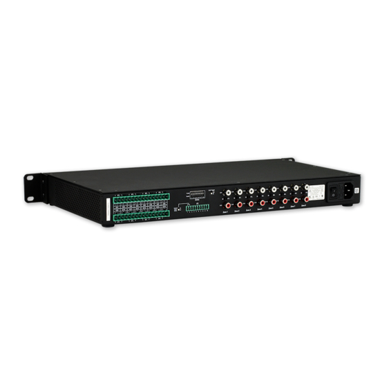
The Alero ALR-AMP-8 supports up to eight stereo input devices, each one associated with an input Zone (1-8). Note that each Zone represents a stereo pair. For example, Zone 1 consists of CH1 (left channel) and Ch2 (right channel). -
Page 13: Connecting Input Devices In Bridge Mode
Speaker (Output) Terminals (16 total, L/R pairs for eight stereo outputs) Each Zone (1-8) consists of two channels (an L/R pair in Stereo Mode), and each Channel (1-16) uses a 2-pin captive- wire connector to connect to speakers. ALR-AMP-8 Alero 8 Zone Power Amplifier... -
Page 14: Speaker Output Connectors
Even-numbered channels should be used to connect to the right speaker. The ALR-AMP-8 supports up to eight stereo speaker pairs, each one associated with a Zone (1-8). FIG. 8 illustrates the wiring connection from both Zone output channels to a stereo speaker pair:... -
Page 15: Connecting Speakers In Bridge Mode
CH7 (left) CH7 (+) / CH8 (+) CH9 (left) CH9 (+) / CH10 (+) CH11 (left) CH11 (+) / CH12 (+) CH13 (left) CH13 (+) / CH14 (+) CH15 (left) CH15 (+) / CH16 (+) ALR-AMP-8 Alero 8 Zone Power Amplifier... -
Page 16: I/O (Control Input) Port
Plug = + (Stereo Outputs) ALR-AMP-8 I/O Port Pin 1 = Signal Sense + Stereo Inputs Pin 2 = Signal GND Pin 5 = GND FIG. 11 PIN 1 Example - Signal Sense Connection (Unbalanced) ALR-AMP-8 Alero 8 Zone Power Amplifier... -
Page 17: External Signal Sense Switch
Pin 3 = 12V Trigger In Pin 10 = Status GND FIG. 13 PIN 4 Example - Trigger (Loop Out) Connections Pin 4 connects to a +12V Trigger (input) on a downstream amplifier (see FIG. 12). ALR-AMP-8 Alero 8 Zone Power Amplifier... -
Page 18: Pin 5 - Local/Trigger Gnd
I/O pin on an external controller such as a NetLinx Central Controller (see FIG. 15). NetLinx Central Controller ALR-AMP-8 Pin 7 = Thermal Overload Monitor Indicator Pin 8 = OC (Overcurrent) Monitor Indicator Pin 10 = GND FIG. 15 Example - Thermal and OC Indicator Connections ALR-AMP-8 Alero 8 Zone Power Amplifier... -
Page 19: Pin 9 - On Signal Output / 12V Trigger
Pin 10 = Status GND FIG. 16 Pin 9 Example Connection - On Signal Output Connections Refer to AMX Tech Note #777 for details regarding configuring the the I/O ports on a NetLinx Master to accept a voltage input. 12V Trigger Pin 9 also functions as a 12V on/off output trigger. -
Page 20: Pin 10 - Status Gnd
On/Off Control (12V Trigger, 3-5V Trigger and Signal Sense) The Alero ALR-AMP-8 can be powered on and off externally by using the two signals 12V trigger and 3-5V trigger. A Signal Sense function is also provided which automatically can switch on the Alero in the event of an audio signal and switch off the Alero to enter standby mode when no audio signal has been present on the signal terminals for approximately 13 minutes. -
Page 21: Applying Power To The Alero Amplifier
Note that the POWER LED on the front panel lights Red to indicate that the amplifier is receiving power, but is in Standby mode. Also note that when in Standby mode, the 12V output trigger is turned off. ALR-AMP-8 Alero 8 Zone Power Amplifier... -
Page 22: Netlinx Programming Example: On Signal, Oc And Thermal Functions
[dvTP,123] = [dvIO,1] // reflect the state of the amplifier on touch panel button 123 [dvTP,124] = [dvIO,2] // turn the button on when AMP8 is in Over Current Protection [dvTP,125] = [dvIO,3] // turn the button on when AMP8 is in Thermal shutdown ALR-AMP-8 Alero 8 Zone Power Amplifier... - Page 23 Installation ALR-AMP-8 Alero 8 Zone Power Amplifier...
- Page 24 - Schedules and registration for any AMX University course - Travel and hotel information - Your individual certification requirements and progress 3000 RESEARCH DRIVE, RICHARDSON, TX 75082 USA • 800.222.0193 • 469.624.8000 • 469-624-7153 fax • 800.932.6993 technical support • www.amx.com...
Need help?
Do you have a question about the ALR-AMP-8 and is the answer not in the manual?
Questions and answers